

Page 1

ioLogik E4200
Quick Installation Guide
Second Edition, May 2009
© 2009 Moxa Inc. All rights reserved.
Reproduction without permission is prohibited.
P/N: 1802042000011
Page 2
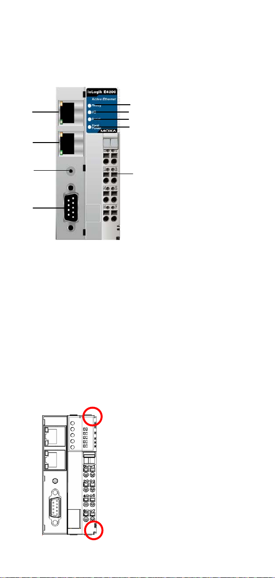
Introduction
The ioLogik E4200 comes equipped with 2 Ethernet ports and 1 RS-232 port,
making it suitable for remote monitoring and alarm system applications that
require multiple I/O points of various types.
1
2
3
4
5
6
7
8
1. LAN 1
2. LAN 0
3. Reset Button
4. COM (RS-232 Port)
5. Ready LED
6. I/O LED
9
7. Serial LED
8. Field Power LED
9. Removable Terminal
Block (RTB)
Package Checklist
Moxa’s ioLogik E4200 is shipped with the following items. If any of these
items are missing or damaged, please contact your customer service
representative for assistance.
y 1 ioLogik E4200 Active Ethernet Network Adaptor.
y Quick Installation Guide.
y Software CD with User’s Manual and Windows Utility.
y End Module Cover.
Installing the I/O Module on a DIN-Rail
Step1: Align the I/O module side by side with the network adaptor, making
sure that the upper and lower rails are hooked together.
- 2 -
Page 3
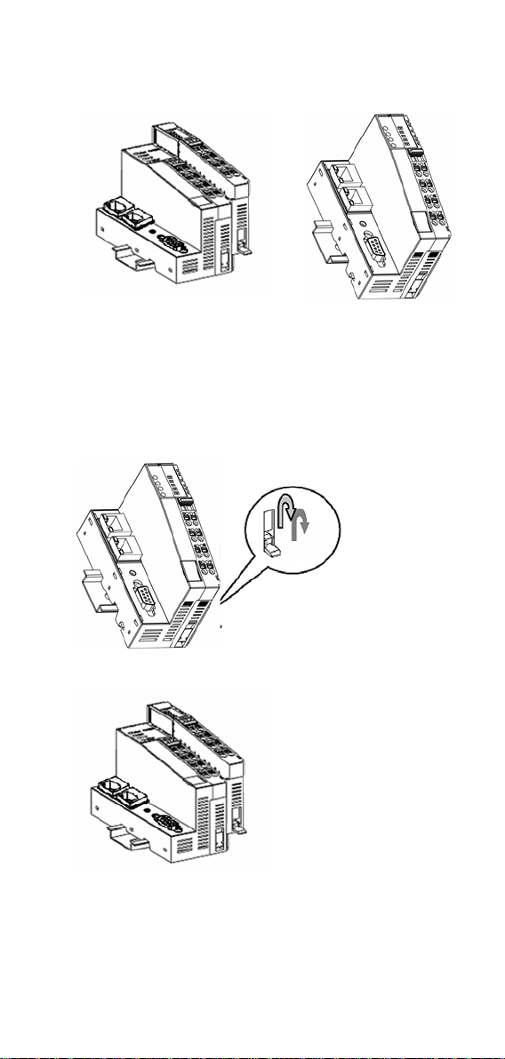
Step 2: Align the I/O module side by side with the network module and then
push the I/O module until it touches the DIN-rail. Next, apply more
force until the module clips to the DIN-rail.
Removing the I/O Module from the
DIN-Rail
Step1: Use your finger or a screw driver to pull down the tab on the lower
part of the module.
Step2: While still holding down the tab, pull out the Module.
- 3 -
Page 4

Remove the RTB from the I/O module
Pull out the plastic belt from the RTB, and then apply more force until the I/O
module is pulled away from the I/O module.
Installing the RTB onto the I/O Module
Step1: Hook the bottom end of the RTB to the I/O module.
Step2: Push down the RTB until it fits snugly on the I/O module, and then
push in the plastic belt.
Installing the System Power Module
The system power expansion module is designed to provide extra power when
additional I/O expansion modules are connected. Each ioLogik E4200 can
provide 1.5A @ 5 VDC. If you require more power for your installed I/O
expansion modules, you will need to use an M-7001 module. However, please
note that the M-7001 can only provide 1A @ 5 VDC.
150 mA
150 mA
150 mA
150 mA
150 mA
150 mA
150 mA
Total: 1400 mA
150 mA
200 mA Supports 1000 mA
200 mA
200 mA
200 mA
Total: 1000 mA
Supports 1000 mA
200 mA
200 mA
Supports 1000 mA
- 4 -
Page 5

Installing the Field Power Module
The field power distributor is designed to isolate different field voltages. For
example, before you connect a 110 VDC or 220 VAC AC-Digital Input
module to a 24 VDC DI/O module, you will need an M-7002 field power
distributor.
0V 24V
24 VDC
0V 110V
110 VDC
220 VAC
0V
220 VAC
Connecting the Power System
Two 24 VDC power sources are required to power the ioLogik E4200. One 24
VDC power input is for system power, and the other 24 VDC power input is
for the field I/O. For field installation, system power and field power are
provided by different power supply systems.
ioLogik E4200
READY
I/O
SERIAL
Field
Power
0 1
24V
2 3
SG
4 5
0V 0V
6 7
24V 24V
System Bus
0V
SG
System Power (5 VDC)
System Power (GND)
Non-isolation
Switching
Power
System Power (0 VDC)
System Power (24 VDC)
Shielding Ground
Field Power (0 VDC)
Field Power (24 VDC)
Field Power (0 VDC)
Field Power (24 VDC)
System power:
24 VDC nominal, 11 to 28.8 VDC
Power dissipation:
60 mA@ 24 VDC
Current for I/O module:
1.5A @ 5 VDC
Field power :
11 to 28.8 VDC
Max. current for field power
contact: DC 10A Max.
I/O Cable Gauge:
AWG14 to AWG28
- 5 -
Page 6

Supported Modules
DC-Digital Input Modules
M-1800 8 digital inputs, sink, 24 VDC, removable terminal block
M-1801 8 digital inputs, source, 24 VDC, removable terminal block
M-1600 16 digital inputs, sink, 24 VDC, 20-pin header
M-1601 16 digital inputs, source, 24 VDC, 20-pin header
AC-Digital Input Modules
M-1450 4 digital inputs,110 VAC, removable terminal block
M-1451 4 digital inputs, 220 VAC, removable terminal block
Digital Output Modules
M-2800 8 digital outputs, sink, 24 VDC, 0.5A, removable terminal
block
M-2801 8 digital outputs, source, 24 VDC, 0.5A, removable terminal
block
M-2600 16 digital outputs, sink, 24 VDC, 0.3A, 20-pin header
M-2601 16 digital outputs, sink, 24 VDC, 0.3A, 20-pin header
Relay Output Modules
M-2450 4 Relay outputs, Form A (N.O.), 2A, removable term inal
block
Analog Input Modules
M-3802 8 analog inputs, 4 to 20 mA, 12-bit, removable terminal block
M-3810 8 analog inputs, 0 to 10V, 12-bit, removable terminal block
Temperature Input Modules
M-6200 2 analog inputs, RTD, removable terminal block
M-6201 2 analog inputs, thermocouple, removable terminal block
Analog Output Modules
M-4402 4 analog outputs, 4 to 20 mA, 12-bit, removable terminal
block
M-4410 4 analog outputs, 0 to 10V, 12-bit, removable terminal block
System Modules
M-7001 System expansion power supply, 1.0 A (5 VDC)
M-7002 Field power distributor, 10 A (24/48 VDC, 110/220 VAC)
M-7806 Potential distributor, 8 ch, 4 ch / 24 VDC, 4ch / 0 VDC
- 6 -
Page 7

Accessories
TB 1600 DIN-rail mounting screw terminal
module with 20-pin connector
• 20 pins, one-to-one assignment
• Connector pitch: 3.81 mm
• DIN-rail mounting type
• Dimensions (W x L x H): 77.5 x 67.5 x 51 mm
• RoHS compliant
20-pin to 20-pin flat cable
• Connecting between TB 1600 and ioLogik 4000
series
• Length:50 cm
• Number of pins: 20
M-8001-PK Removable terminal block
• Terminal block for ioLogik 4000 series
• Packaging: 9 pcs in one box
M-8003-PK Marker with 0 to9 numbering
M-8004-PK Blank marker
• Marker for ioLogik 4000 series
• Packaging: 100 pcs in one box
Technical Support Contact Information
www.moxa.com/support
Moxa Americas:
Toll-free: 1-888-669-2872
Tel: +1-714-528-6777
Fax: +1-714-528-6778
Moxa Europe:
Tel: +49-89-3 70 03 99-0
Fax: +49-89-3 70 03 99-99
Moxa China (Shanghai office):
Toll-free: 800-820-5036
Tel: +86-21-5258-9955
Fax: +86-10-6872-3958
Moxa Asia-Pacific:
Tel: +886-2-8919-1230
Fax: +886-2-8919-1231
- 7 -
 Loading...