

Page 1

CN2600 Series Dual-LAN Terminal Server
User’s Manual
Tenth Edition, August 2015
www.moxa.com/product
© 2015 Moxa Inc. All rights reserved.
Page 2

CN2600 Series Dual-LAN Terminal Server
Moxa Americas
Toll
Tel:
Fax:
Moxa China (Shanghai office)
Toll
Tel:
Fax:
Moxa Europe
Tel:
Fax:
Moxa Asia
Tel:
Fax:
User’s Manual
The software described in this manual is furnished under a license agreement and may be used only in accordance with
the terms of that agreement.
Copyright Notice
Copyright ©2015 Moxa Inc.
Trademarks
The MOXA logo is a registered trademark of Moxa Inc.
All other trademarks or registered marks in this manual belong to their respective manufacturers.
Disclaimer
Information in this document is subject to change without notice and does not represent a commitment on the part of
Moxa.
Moxa provides this document as is, without warranty of any kind, e ither expre sse d or i mplied, including, but not limited
to, its particular purpose. Moxa reserves the right to make improvements and/or changes to this manual, or to the
products and/or the programs described in this manual, at any time.
Information provided in this manual is intended to be accurate and reliable. However, Moxa assumes no responsibility for
its use, or for any infringements on the rights of third parties that may result from its use.
This product might include unintentional technical or typographical errors. Changes are periodically made to the
information herein to correct such errors, and these changes are incorporated into new editions of the publication.
Technical Support Contact Information
www.moxa.com/support
-free: 1-888-669-2872
+1-714-528-6777
+1-714-528-6778
+49-89-3 70 03 99-0
+49-89-3 70 03 99-99
-free: 800-820-5036
+86-21-5258-9955
+86-21-5258-5505
-Pacific
+886-2-8919-1230
+886-2-8919-1231
Page 3

Table of Contents
1. Introduction ...................................................................................................................................... 1-1
Package Checklist ............................................................................................................................... 1-2
Product Features ................................................................................................................................ 1-2
Product Specifications ......................................................................................................................... 1-2
Front Panel ........................................................................................................................................ 1-4
Rear Panel ......................................................................................................................................... 1-5
Bottom Label ..................................................................................................................................... 1-6
2. Hardware Installation ....................................................................................................................... 2-1
Desktop ............................................................................................................................................. 2-2
Rackmount ........................................................................................................................................ 2-2
Wiring Requirements ........................................................................................................................... 2-2
Connecting the CN2600-8/16’s Power ................................................................................................... 2-3
Connecting the CN2600-8/16-HV’s Power .............................................................................................. 2-3
Grounding the CN2600-8/16-HV ........................................................................................................... 2-4
Connecting to the Network ................................................................................................................... 2-4
Connecting to a Serial Device ............................................................................................................... 2-4
Connecting to the Console Port ............................................................................................................. 2-4
Adjustable Pull High/Low Resistors for the RS-485 Port ........................................................................... 2-5
3. Initial IP Address Configuration ........................................................................................................ 3-1
Static and Dynamic IP Addresses .......................................................................................................... 3-2
Factory Default IP Address ................................................................................................................... 3-2
Configuration Options .......................................................................................................................... 3-2
Terminal Server Search Utility ...................................................................................................... 3-2
Web Console ............................................................................................................................... 3-2
LCM Console/Front Panel .............................................................................................................. 3-2
ARP ........................................................................................................................................... 3-3
Telnet Console ............................................................................................................................ 3-4
Serial Console ............................................................................................................................. 3-7
4. Serial Port Operation Modes .............................................................................................................. 4-1
Overview ........................................................................................................................................... 4-2
Device Control Applications .................................................................................................................. 4-2
Real COM Mode ........................................................................................................................... 4-2
RFC2217 Mode ............................................................................................................................ 4-3
Socket Applications ............................................................................................................................. 4-3
TCP Server Mode ......................................................................................................................... 4-3
TCP Client Mode .......................................................................................................................... 4-3
UDP Mode .................................................................................................................................. 4-4
Redundant COM ................................................................................................................................. 4-4
Dual-host Redundant Data Acquisition System (DRDAS) .......................................................................... 4-5
Terminal Applications .......................................................................................................................... 4-6
Terminal ASCII Mode ................................................................................................................... 4-6
Terminal BIN Mode ...................................................................................................................... 4-6
Reverse Terminal Applications .............................................................................................................. 4-7
Reverse Telnet ............................................................................................................................ 4-7
Dial In/Out Modes ............................................................................................................................... 4-8
Disabled Mode .................................................................................................................................... 4-8
5. Configuration with the Web Console ................................................................................................. 5-1
Using Your Web Browser...................................................................................................................... 5-2
Browser Cookie Settings............................................................................................................... 5-2
Trusted Site Settings ................................................................................................................... 5-3
Opening the Web Console............................................................................................................. 5-4
Web Console Navigation ...................................................................................................................... 5-5
Basic Settings .................................................................................................................................... 5-5
Server Settings ........................................................................................................................... 5-5
Time Settings ............................................................................................................................. 5-5
Network Settings ................................................................................................................................ 5-6
Basic Network Settings ................................................................................................................ 5-6
Advanced Network Settings .......................................................................................................... 5-8
What is RIP? ....................................................................................................................... 5-8
Configuring the Rou te Table ......................................................................................................... 5-9
Configuring Routes to the Internet ....................................................................................... 5-10
Configuring Routes to the Intranet ....................................................................................... 5-11
Configuring Multiple-Point Route s ......................................................................................... 5-12
6. Configuring Serial Port Operation Modes .......................................................................................... 6-1
Port Setting Basics .............................................................................................................................. 6-2
Device Control Applications .................................................................................................................. 6-3
Page 4

Real COM Mode ........................................................................................................................... 6-3
RFC2217 Mode ............................................................................................................................ 6-5
Socket Applications ............................................................................................................................. 6-6
TCP Server Mode ......................................................................................................................... 6-6
TCP Client Mode .......................................................................................................................... 6-8
UDP Mode ................................................................................................................................ 6-11
Redundant COM ............................................................................................................................... 6-12
DRDAS ............................................................................................................................................ 6-14
DRDAS Real COM ...................................................................................................................... 6-14
DRDAS TCP Server .................................................................................................................... 6-16
Terminal Applications ........................................................................................................................ 6-18
Terminal ASCII (TERM_ASC) ....................................................................................................... 6-18
Terminal BIN (TERM_BIN) .......................................................................................................... 6-19
Reverse Terminal .............................................................................................................................. 6-21
Dial In/Out Applications ..................................................................................................................... 6-22
PPP Mode ................................................................................................................................. 6-22
PPPD Mode ............................................................................................................................... 6-23
SLIP Mode ................................................................................................................................ 6-24
SLIPD Mode .............................................................................................................................. 6-25
Dynamic Mode .......................................................................................................................... 6-26
Disabled Mode .................................................................................................................................. 6-26
7. Additional Serial Port Settings .......................................................................................................... 7-1
Port Communication Parameters ........................................................................................................... 7-2
Serial Parameters ............................................................................................................................... 7-2
Port Data Buffering/Log ....................................................................................................................... 7-3
Port Modem Settings ........................................................................................................................... 7-3
Welcome Message .............................................................................................................................. 7-4
8. System Management Settings ........................................................................................................... 8-1
Misc. Network Settings ........................................................................................................................ 8-2
Accessible IP List ......................................................................................................................... 8-2
SNMP Agent Settings ................................................................................................................... 8-3
Read-only and Read/write access control ................................................................................ 8-3
DDNS ........................................................................................................................................ 8-4
Host Table .................................................................................................................................. 8-4
User Table .................................................................................................................................. 8-5
Authentication Server .................................................................................................................. 8-5
System Log Settings .................................................................................................................... 8-6
Auto Warning Settings ......................................................................................................................... 8-6
Event Settings ............................................................................................................................ 8-6
Serial Event Settings ................................................................................................................... 8-7
E-mail Alert ................................................................................................................................ 8-8
SNMP Trap ................................................................................................................................. 8-9
Maintenance ...................................................................................................................................... 8-9
Console Setting ........................................................................................................................... 8-9
Ping ......................................................................................................................................... 8-10
Firmware Upgrade ..................................................................................................................... 8-10
Configurating Import/Export ....................................................................................................... 8-11
Load Factory Defaults ................................................................................................................ 8-12
Change Password ...................................................................................................................... 8-12
Certificate ........................................................................................................................................ 8-13
Ethernet SSL Certificate Import ................................................................................................... 8-13
Certificate/Key De l ete ................................................................................................................ 8-13
System Monitoring ............................................................................................................................ 8-13
Serial to Network Connections .................................................................................................... 8-13
Serial Port Status ...................................................................................................................... 8-14
Serial Port Error Count ............................................................................................................... 8-14
Serial Port Settings .................................................................................................................... 8-14
Network Connections ................................................................................................................. 8-15
Network Statistics ..................................................................................................................... 8-15
Serial Data Log ......................................................................................................................... 8-16
System Log .............................................................................................................................. 8-16
Routing .................................................................................................................................... 8-17
Save Configuration ........................................................................................................................... 8-17
Restart ............................................................................................................................................ 8-18
Restart System ......................................................................................................................... 8-18
Restart Ports ............................................................................................................................ 8-18
9. Software Installation/Configuration ................................................................................................. 9-1
NPort Search Utility ............................................................................................................................. 9-2
Installing NPort Search Utility ....................................................................................................... 9-2
Configuring NPort Search Utility .................................................................................................... 9-4
Windows Driver Manager ..................................................................................................................... 9-5
Page 5

Installing NPort Windows Driver Manager ....................................................................................... 9-5
Using NPort Windows Driver Manager ............................................................................................ 9-7
Windows Monitor Utility ..................................................................................................................... 9-14
Installing the NPort Mon ito r Ut il ity ............................................................................................... 9-14
Using the NPort Monitor Utility .................................................................................................... 9-16
Linux Real TTY Driver s ...................................................................................................................... 9-18
Basic Procedures ....................................................................................................................... 9-18
Hardware Setup ........................................................................................................................ 9-18
Installing Linux Real TTY Driver Files ........................................................................................... 9-18
Mapping TTY Ports ..................................................................................................................... 9-19
Real COM Mode ................................................................................................................. 9-19
Mapping TTY Ports Automatically .................................................................................. 9-19
Mapping TTY Ports Manually ......................................................................................... 9-19
Redundant COM Mode ........................................................................................................ 9-19
Mapping TTY Ports ...................................................................................................... 9-20
Removing Mapped TTY Ports ....................................................................................................... 9-20
Removing Linux Driver Files ........................................................................................................ 9-20
The UNIX Fixed TTY Driver ................................................................................................................. 9-21
Installing the UNIX Driver .......................................................................................................... 9-21
Configuring the UNIX Drive r ....................................................................................................... 9-21
Modify the configuration: .................................................................................................... 9-21
Device naming rule ............................................................................................................ 9-22
Starting moxattyd .............................................................................................................. 9-22
Adding an additional server ................................................................................................. 9-22
A. Pinouts and Cable Wiring .................................................................................................................. A-1
Port Pinout Diagrams .......................................................................................................................... A-2
RS-232/422/485 (Male DB9) Pinouts ............................................................................................. A-2
RS-232 (Male DB9) Pinouts .......................................................................................................... A-2
RS-232 (Male RJ45) Pinouts ......................................................................................................... A-3
RS-232/422/485 (Male RJ45) Pinouts ............................................................................................ A-3
Cable Wiring Diagrams ........................................................................................................................ A-4
Ethernet Cables .......................................................................................................................... A-4
Serial Cables (RS-232) ................................................................................................................. A-4
RJ45 (8-pins) to Female DB9 ................................................................................................. A-4
RJ45 (8-pins) to Male DB9 .................................................................................................... A-5
RJ45 (8-pins) to Female DB25 ............................................................................................... A-5
RJ45 (8-pins) to Male DB25 ................................................................................................... A-5
Serial Cables (RS-422/4-Wire RS-485) ........................................................................................... A-6
RJ45 (8-pins) to Female DB9 ................................................................................................. A-6
RJ45 (8-pins) to Male DB9 .................................................................................................... A-6
RJ45 (8-pins) to Female DB25 ............................................................................................... A-6
RJ45 (8-pins) to Male DB25 ................................................................................................... A-7
Serial Cables (2-Wire RS-485) ...................................................................................................... A-7
RJ45 (8-pins) to Female DB9 ................................................................................................. A-7
RJ45 (8-pins) to Male DB9 .................................................................................................... A-7
RJ45 (8-pins) to Female DB25 ............................................................................................... A-7
RJ45 (8-pins) to Male DB25 ................................................................................................... A-8
Pin Assignments for DB9 and DB25 Connectors ............................................................................... A-8
Pin Assignments for DB9 Male and Female Connectors .............................................................. A-8
Pin Assignments for DB25 Male and Female Connectors ............................................................ A-8
B. SNMP Agent with MIB II ................................................................................................................... B-1
C. Dynamic Domain Name Server .......................................................................................................... C-1
Overview ........................................................................................................................................... C-1
Configuration ..................................................................................................................................... C-2
D. Well Known Port Numbers ................................................................................................................ D-1
E. RADIUS Server .................................................................................................................................. E-1
What is RADIUS? ................................................................................................................................ E-2
Definition ................................................................................................................................... E-2
Client/Server Architecture ............................................................................................................ E-2
Setting up the CN2600 ........................................................................................................................ E-3
Setting up the RADIUS Server IP Address....................................................................................... E-3
Serial Port Configuration .............................................................................................................. E-3
Setting up UNIX Hosts ......................................................................................................................... E-3
Setting up Windows NT Hosts ............................................................................................................... E-4
Setting up Windows 2000 Hosts ........................................................................................................... E-5
Setting up Windows 2003 Hosts ........................................................................................................... E-7
F. CN2600 Series Comparison Table ...................................................................................................... F-1
Page 6

1
NOTE
In th
NOTE
The wide temperature model does not have an LCM Display panel and push buttons. The LCM description in this
manual applies only to standard temperatu
1. Introduction
Moxa’s CN2600 series of dual-LAN termi na l ser ve rs i s ava il a ble in mo de l s wi th 8 or 16 RS-232 or
RS-232/422/485 ports, and all models come with two 10/100 Mbps Etherne t LAN ports. The CN2600 dual-LAN
terminal servers are used to connec t terminals, modems, printers, and other asynchronous serial devi ces to
LAN hosts. The CN2600 dual-LAN terminal servers comply with TCP/IP and IEEE 802.3 specifications using
standard Ethernet 10/100BaseT and twisted pair 10/100BaseTX cable as the data transmission medium.
is manual, we often refer to all termi na l servers in the CN2600 series collectively as the CN2600.
re models.
The following topics are covered in this chapter:
Package Checklist
Product Features
Product Specifications
Front Panel
Rear Panel
Bottom Label
Page 7

CN2600 Series Introduction
1-2
Ethernet Interface
Number of Ports:
Speed:
Connector:
Magnetic Isolation:
Serial Interface
Number of Ports:
Serial Standards:
CN2610: RS
CN2650/2650I: RS
Connector:
CN2610/2650: 8
CN2650I: DB9 male
RS
Serial Line Protection:
2 kV optical isolation (CN2650I)
Console Port:
Serial Communication Parameters
Data Bits:
Stop Bits:
Parity:
Flow Control:
Baudrate:
Pull High/Low Resistor for RS
Terminator for RS
Package Checklist
All CN2600 dual-LAN terminal servers are shipped with the following items:
• CN2600 dual-LAN terminal server
• Power cord (AC models only)
• Document and Software CD-ROM
• Quick Installation G uide (English and Si m plified Chinese versions)
• RJ45 Loopback Tester
• Product Warranty Statement
• Rackmount Kit (includes 2 brackets and 8 screws)
• Desktop Kit (includes 4 pads)
Product Features
The CN 2600 series has the following features:
• LCD panel for easy IP address configuration (excluding wide temperature models)
• Dual-LAN cards with two independent MAC addresses and IP addresses
• Redundant COM function available when both LANs are active
• Dual-host redundancy can be used to add a backup PC to your system
• Dual AC power inputs (AC models only)
• Real COM/TTY drivers for Windows and Linux
• Universal high-voltage range: 100 to 240 VAC or 88 to 300 VDC
Product Specifications
2 (2 IPs)
10/100 Mbps, auto MDI/MDIX
8-pin RJ45
1.5 kV built-in
8 or 16
-232
-232/422/485
-pin RJ45
-485 Data Direction Control: ADDC® (Automatic Data Direction Contro l)
Dedicated RS-232 console port on rear panel (8-pin RJ45)
5, 6, 7, 8
1, 1.5, 2
None, Even, Odd, Space, Mark
RTS/CTS, DTR/DSR, XON/XOFF
50 bps to 921.6 kbps
-485: 1 kΩ, 150 kΩ
-485: 120 Ω
Page 8

CN2600 Series Introduction
1-3
Serial Signals
RS
RS
RS
RS
Software
Network Protocols:
DDNS
Security Protocols:
Configuration Options:
Windows Real COM Drivers:
(x86/x64), Windows 2008 R2/2012/2012 R2 (x64), Windows Embedded CE 5.0/6.0, Windows XP Embedded
Fixed TTY Drivers: SCO Unix, SCO OpenServer, UnixWare 7, QNX 4.25, QNX 6, Solaris 10, FreeBSD, AIX 5.x,
HP
Linux Real TTY Drivers:
Management:
IP Routing:
Operation Modes
Standard:
Redundant COM, Disabled
Applications
Terminal Sessions:
Physical Characteristics
Housing:
Weight:
CN2610
CN2610
CN2650
CN2650
CN2650
CN2650
CN2650I
CN2650I
CN2650I
CN2650I
CN2650I
CN2650I
Dimensions:
Without ears: 440 x 198 x 45.5 mm (17.32 x 7.80 x 1.77 in)
With ears: 480 x 198 x 45.5 mm (18.9 x 7.80 x 1.77 in)
Environmental Limits
Oper
Standard Models: 0 to 55°C (32 to 131°F)
Wide Temp. Models:
High Voltage Wide Temp. Models:
Storage Temperature:
Standard Models:
Wide Temp. Models:
High Voltage Wide Temp. Models:
Ambient Relative Humid it y:
Altitude:
Note: Please contact Moxa if you require products guaranteed to function properly at higher altit
-232: TxD, RxD, RTS, CTS, DTR, DSR, DC D, GN D
-422: Tx+, Tx-, Rx+, Rx-, GND
-485-4w: Tx+, Tx-, Rx+, Rx-, GND
-485-2w: Data+, Data-, GND
ICMP, IPv4, TCP, UDP, DHCP, BOOTP, Telnet, DNS, SNMP, HTTP, SMTP, ARP, PPPoE ,
RADIUS, HTTPS, SSH, PAP, CHAP
Web Console, Serial Console, Telnet Console, Windows Search Utility
Windows 95/98/ME/NT/2000, Windows XP/2003/Vista/2008/7/8/8.1
-UX 11i, Mac OS X
Linux 2.4.x, 2.6.x, 3.x
SNMP MIB-II
Static, RIP-I, RIP-II
Real COM, TCP Server, TCP Client, UDP, RFC2217 , Terminal, Reverse Telnet, PPP, DRDAS,
8 sessions per port
Metal
-8-2AC: 3760 g
-16-2AC: 3810 g
-8: 3740 g
-16: 3790 g
-8-2AC: 3900 g
-16-2AC: 3980 g
-8: 3666 g
-16: 3776 g
-8-2AC: 3932 g
-16-2AC: 4022 g
-8-HV: 3910 g
-16-HV: 3930 g
ating Temperature:
-40 to 75°C (-40 to 167°F)
-40 to 85°C (-40 to 185°F)
Up to 2000 m
-40 to 75°C (-40 to 167°F)
-40 to 75°C (-40 to 167°F)
-40 to 85°C (-40 to 185°F)
5 to 95% (non-condensing)
udes.
Page 9

CN2600 Series Introduction
1-4
Power Requirements
Input Voltage:
AC Models: 100 to 240 VAC, 47 to 63 Hz, 280 mA
HVDC
Power Consumption:
CN2650 AC models: 235 mA @ 100 VAC, 145 mA @ 240 VAC
CN2650I HV models: 152 mA @ 88 VDC, 86 mA @ 300 VDC
Power Line P
Standards and Certifications
EMI:
EMS:
EN 61000
EN 61000
EN 61000
EN 61000
EN 61000
EN 61000
EN 61000
Safety:
EMC:
Freefall:
Vib
Green Product:
Reliability
Alert Tools:
Automatic Reboot Trigger:
MTBF (mean time between failures ):
CN2650I AC models: 99,320 hrs
CN2650I
CN2650I
Warranty
Warranty Period:
Details:
NOTE
Wide temperature models do not have
Models: 88 to 300 VDC
rotection: 1 kV burst (EN 61000-4-4: EFT/B), 2 kV surge (EN 61000-4-5)
EN 55022 Class A, FCC part 15 Subpart B Class A
-4-2 ESD: contact 4 kV; air 8 kV
-4-3 RS: 3 V/m (80 MHz to 1 GHz)
-4-4 EFT: Power 4 kV; Signal 2 kV
-4-5 Surge: AC 1 kV (AC models); DC 2 kV (HV models); Signal 1 kV
-4-6 CS: 3 V
-4-8
-4-11: AC models only
UL 60950-1, EN 60950-1
55022/24
IEC-68-2-34, IEC-68-2-32
ration: IEC-68-2-6
RoHS, CRoHS, WEEE
Built-in buzzer and RTC (real-time clock)
-8-HV-T: 191,326 hrs
-16-HV-T: 116,924 hrs
See www.moxa.com/warranty
Front Panel
Built-in WDT (watchdog timer)
5 years
an LCM Display Panel.
Page 10

CN2600 Series Introduction
1-5
Buttons
Item Description
Reset Button Press the Reset button for 5 seconds to load factory defaults. The CN2600 will beep twice
when the configuration has been reset.
Push Buttons Used for configuring the IP address and other parameters.
LEDs
Item Description
Ready Red Indicates that the CN2600 is receiving power
Green Indicates that the CN2600’s OS is ready
Tx Green Indicates serial port transmiss io n
Rx Yellow Indicates serial port reception
LAN 1, LAN 2 Green Ethernet link connection
Off Ethernet cable is disconnected
PWR 1, PWR 2 Red Power connection
Off Power cable is disconnected
Rear Panel
Socket / Port Description
AC Power Input Automatic detection of 100 to 240 V, 47 to 63 Hz AC power supply
DC Power Input Automatic detection of 88 to 300 V
Power On/Off Switch I indicates power on; O indicates power off (AC models only)
Console 8-pin RJ45 RS-232 port for console terminal connection
LAN 1 8-pin RJ45 auto-detectable 10/100 Mbps UTP port
LAN 2 8-pin RJ45 auto-detectable 10/100 Mbps UTP port
Serial Ports 8 or 16 8-pin RJ45 or DB9 ports for DCE modem-type connections
Page 11

CN2600 Series Introduction
1-6
Bottom Label
The server’s serial number and MAC address are printed on a label fixed to the bottom of the server. The
CN2600 has 2 LAN ports, each with its own MAC address. The MAC address is the unique hardware Ethernet
address used to identify a network hardware product. Write each of the two MAC addresses in the space
provided below for future reference.
LAN 1 MAC address:_______________________________
LAN 2 MAC address:_______________________________
Page 12

2
2. Hardware Installation
This chapter includes instructions on where and how to install the CN2600 dual-LAN terminal server. Both basic
and advanced software configuration instructions are given.
The following topics are covered in this chapter:
Desktop
Rackmount
Wiring Requirements
Connecting the CN2600-8/16’s Power
Connecting the CN2600-8/16-HV’s Power
Grounding the CN2600-8/16-HV
Connecting to the Network
Connecting to a Serial Device
Connecting to the Console Port
Adjustable Pull High/Low Resis t ors for the RS-485 Port
Page 13

CN2600 Series Hardware Installation
2-2
ATTENTION
Safety First!
Be sure to disconnect the power cord before installing and/or wiring your CN2600.
Wiring Caution!
Calculate the maximum possible current in each power wire and commo
dictating the maximum current allowable for each wire size.
If the current goes above the maximum ratings, the wiring could overheat, causing serious damage to your
equipment.
Temperature Caution!
Be careful when handling the CN2600. When plugged in, the CN2600’s internal components generate heat, and
consequently the board may feel hot to the touch.
NOTE
Do not run signal or communication wiring and power wiring in the same wire conduit. To avoid interference,
wires with different signal
Desktop
Place your CN2600 on a clean, flat, well-ventilated desktop. For better ventilation, attach the 4 pads from the
desktop kit to the bottom of the unit, and leave some space between the CN2600 and other equipment. Do not
place equipment or objects on top of the unit, as this might damage the server.
Rackmount
The CN2600 is designed to be mounted on a standard 19-inch rack. Use the enclosed pair of L-shaped metal
brackets and screws to fasten your CN2600 to the rack cabinet. Each L-shaped bracket has 6 holes, leaving two
outer or inner holes available for other uses. You have two options. You can lock either the front or rear panel
of the CN2600 to the front of the rack. Locking the front panel is shown in the following figure.
Wiring Requirements
You should also observe the following common wiring rules:
• Use separate paths to route wiring for power and devices. If power wiring and device wiring paths must
cross, make sure the wires are perpendicular at the intersection point.
n wire. Observe all electrical codes
characteristics should be routed separately.
Page 14

CN2600 Series Hardware Installation
2-3
WARNING
CL 1.7.9 Isolation of multiple power sources & CL 3.4.11 Multiple power sources:
Where there is more than one connection supplying HAZARDOUS VOLTAGES or HAZARDOUS ENERGY LEVELS
to equipment, a prominent marking, located close to the entry point provided for a SERVICE PERSON to gain
access to the hazardous parts, shall be provided to in
equipment completely and which disconnect devices can be used to isola te each section of the equipment.
CAUTION: This server may be shipped with multiple power supplies that require more than one connector to AC
mains. The AC power cords are considered to be the mains disconnect device for the server; always disconnect
power supply cords before opening up or servicing the server.
NOTE
You should use 8 kg
CN2600
• You can use the type of signal transmitted through a wire to determine which wires should be kept separate.
The rule of thumb is that wiring that sh a res similar electrical characteristics can be bundled together.
• Keep input wiring and output wiring separate.
• Where necessary, it is strongly advised that you label wiring to all d evices in the system.
Connecting the CN2600-8/16’s Power
Connect the CN2600’s 100-240 VAC power line to its AC connector. If the power is properly supplied, the
“Ready” LED will show a solid red color until the system is ready, at whic h time the color changes to green.
dicate which disconnect device or devices isolate the
Connecting the CN2600-8/16-HV’s Power
To connect the CN2600-8/16-HV’s power cord with its terminal b lock, follow the steps given below:
1. Loosen the screws on the V+ and V- termin als of the CN2600-8/16-HV’s terminal blo c k.
2. Connect the power cord’s VDC wire to the terminal block’s V+ terminal, and the power cord’s DC power
ground wire to the terminal block’s V- term inal, and then tighten the terminal blo ck screws. (Note: the
CN2600-8/16-HV can still operate even if the DC and DC power ground are reversed.)
If the power is properly supplied, the “Ready” LED will show a solid red color until the system is ready, at which
time the “Ready” LED will change to a g reen color.
-8/16-HV’s power cord to its terminal block.
-cm of screw torque and 22-14 AWG of suitable electric wire to connect the
Page 15

CN2600 Series Hardware Installation
2-4
ATTENTION
This p
The top right corner LED indicator maintain
connected to a 100 Mbps Ethernet network.
The top left corner LED indicator maintains a solid orange color when the cable is properly
connected to a 10 Mbps Ethernet network.
Grounding the CN2600-8/16-HV
Grounding and wire routing help limi t the effects of noise due to electromag n etic interference (EMI). Run the
ground connection from the grou nd screw to the grounding surface prio r to connecting devices. The shielded
ground (sometimes called protected ground) contact is the second contact from the right o f the 5-pin power
terminal block connector located on the rear panel of the CN2600-8/16-HV. Connect the SG wire to the Earth
ground
roduct is intended to be mounted to a well-grounded mounting surface such as a metal panel.
Connecting to the Network
Connect one end of the Ethernet cable to the CN2600’s 10/100M Ethernet port and the other end of the cable
to the Ethernet network. There are 2 LED indicators located on the top left and right corners of the Ethernet
connector. If the cable is properly connected, the CN2600 will indicate a valid connection to the Ethernet in the
following ways:
s a solid green color when the cable is p r operly
Connecting to a Serial Device
Use appropriately wired serial data cables to connect serial devices to the CN2600’s serial ports.
Connecting to the Console Port
A console is a combination of keyboard and monitor that is used to configure settings and monitor the status
of your system. The console port can be used if a network is unavailable, or you do not know the CN2600’s IP
address. To connect to the console port, use a PC running UNIX, or a PC with terminal emulation software (e.g.,
HyperTerminal or PComm by Moxa; parameter settings are: baudrate = 115200 bps, parity check = None, data
bits = 8, stop bits = 1, terminal type = VT100). Use an RJ45-to-DB25 or RJ45-to-DB9 cable to connect the
terminal to the console port.
Page 16

CN2600 Series Hardware Installation
2-5
ATTENTION
Do no t us e th e 1 KΩ se t t i ng on the CN26
232
s
Adjustable Pull High/Low Resistors for the RS-485 Port
In some critical environments, you may need to add termination resistors to prevent the reflection of serial
signals. When using termination resistors, it is important to set the pull high/low resistors correctly so that the
electrical signal is not corrupted. The CN2600 uses jumper settings or DIP switches to set the pull high/low
resistor values for each serial port.
To set the pull high/low resistors to 150 KΩ, make sure both of the assigned DIP switches are in the OFF
position. This is the default setting.
To set the pull high/low resistors to 1 KΩ, make sure both of the assigned DIP switches are in the ON position.
ignals, shorten the maximum allowed communication distance, and the Rx LED may light up.
50 when using the RS-232 interface. Doing so will degrade the RS-
Page 17

3
3. Initial IP Address Configuration
When setting up the CN2600 for the first time, the first thing you should do is configure its IP address. This
chapter introduces the different methods that can be used. Please refer to Chapt er 8, System Management
Settings, for more details about network settings.
The following topics are covered in this chapter:
Static and Dynamic IP Addresses
Factory Default IP Address
Configuration Options
Terminal Server Search Utility
Web Console
LCM Console/Front Panel
ARP
Telnet Console
Serial Console
Page 18

CN2600 Series Initial IP Address Configuration
3-2
ATTENTION
Consult your network administrator on how to reserve a fixed IP address for your CN2
mapping table when using a DHCP Server or BOOTP Server. For most applications, you should assign a fixed
IP address to your CN2600.
NOTE
The wide temperature model does not have an LCM Display panel and push buttons. The LCM description below
applies only to standard temperature models.
Static and Dynamic IP Addresses
Determine whether your CN2600 needs to use a static IP or dynamic IP address (either DHCP or BOOTP/PPPoE
application).
• If your CN2600 terminal server is used in a static IP environment, you will assign a specific IP
address using one of the tools described in this chapter.
• If your CN2600 terminal server is used in a dynamic IP environment, the IP address will be assigned
automatically from over the network. In this case, set the IP configuration mode to DHCP, DHCP/BOOTP,
BOOTP, or PPPoE.
Factory Default IP Address
The CN2600 is configured with the following default private IP addresses:
192.168.126.254 and 192.168.127.254
Note that IP addresses that begin with “192.168” are referred to as private IP addresses. Devices configured
with a private IP address are not directly accessible from a public network. For example, you would not be able
to ping a device with a private IP address from an outside Internet connection. If your application requires
sending data over a public network, such as the Internet, your CN2600 will need a valid public IP address,
which can be leased from a local ISP.
Configuration Options
Terminal Server Search Utility
600 in the MAC-IP
You may configure your CN2600 with the bundled NPort Se arch Utility for Wi ndows. Please refer to Chapter 9
Software Installation/Configuration, for details on how to install and use Terminal Server Search Utility.
Web Console
You may configure your CN2600 using a standard web browser. Please refer to Chapter 5, Configuration with
the Web console, for details on how to access and use the CN2600 web console.
LCM Console/Front Panel
The CN2600 only gives you the option to configure some settings through the front panel, also known as the
LCM (Liquid Crystal Module) conso le. The LCM console can be configured for read-only or writeable access.
Read-only access allows settings to be viewed but not changed. Fac tory default settings are for writea ble
access, where configuration is a llowed through the LCM console.
Page 19

CN2600 Series Initial IP Address Configuration
3-3
ATTENTION
If a password has been enabled for the CN2600 console and the LCM console is configured for writeable status,
the LCM console will require you to enter the password before allowing you access. The password will not be
required if the LCM console is configured for read
ATTENTION
In order to use the ARP setup method, both your computer and the CN2600 must be connected to the same
LAN. Alternatively, you may use a cross-over Ethernet cable to connect the CN2600 directly to your computer’s
Ethernet card. Before executing the ARP command, your CN2600 must be configured with the factory default
IP address (192.168.127.254) and your computer and the CN2600 must be on the same subnet.
-only access.
The MENU button activates the main menu. It is also used to cancel a selection and return to a previous menu.
The UP and DOWN buttons navigate between available options.
The SEL button confirms a selection or enters a submenu.
The IP environment (Static, DHCP, P PPoE , e tc.) is conf i gu r ed und er Main Menu Network setting
IP config. The IP address is configured under Main Menu
address has been entered, you wi ll need to restart the CN2600 under Main Menu
The following instructions explain how to set the CN260 0’s IP address through the LCM console:
1. Press MENU to activate the Main Menu.
2. The first line of the display indicates the current menu and should read Main Menu. The second line
indicates the current selection and should read Server setting. Use the UP and DOWN buttons to select
Network setting. Press SEL to enter the Network setting menu.
3. In th e Network setting menu, select IP config. Don’t forget to press SEL to confirm your selection.
4. In th e IP config menu, use t he UP and DOWN buttons to select the option that matches your IP
environment (static, DHCP, etc.). Press SEL to confirm your choice. You may also press MENU to cancel
your selection and return to the previous subme nu.
5. You should be back in the Network setting menu. From the Network setting menu, select IP address.
6. Use the UP and DOWN buttons to modify the digit currently selected by the blinking cursor. Press SEL to
move to the next digit. Continue modifying the IP address until all digits have been entered. If you make a
mistake, press MENU to cancel all changes and return to the Network setting menu. You cannot go back
one digit.
7. Once you have finished modifying the IP address, your changes are saved but not in effect. In order for your
changes to take effect, you will need to restart the CN2600. You may view and modify your changes by
selecting IP address at the Network setting menu again.
8. Press the menu button to exit out of the Network setting menu and return to the Main Menu. Use the UP
and DOWN buttons to select Save/Restart and press SEL. Use the UP and DOWN buttons to select Yes
and press SEL to restart.
Network setting IP address. After the
Save/Restart.
ARP
You may use the ARP (Address Resolution Protocol) command to set up an IP address for your CN2600. The
ARP command tells your computer to associate the CN2600’s MAC address with an IP address. Afterwards, use
Telnet to access the CN2600 and its IP address will be reconfigured.
To use ARP to configure the IP addres s, complete the following:
9. Obtain a valid IP address for your CN2600 from your network administrator.
10. Obtain your CN2600’s MAC address from the label on the bottom panel.
Page 20

CN2600 Series Initial IP Address Configuration
3-4
ATTENTION
Figures in this section were taken f r om the CN2600’s Telnet console.
11. Execute the arp -s command from your computer’s MS-DOS prompt as follows:
arp -s <IP address> <MAC address>
For example,
C:\> arp -s 192.168.200.100 00-90-E8-04-00-11
12. Next, execute a special Telnet command by entering the following exactly:
telnet 192.168.200.100 6000
When you enter this command, a Connect failed message will appear, as shown below.
13. After the CN2600 reboots, its IP address will assigned to the new address and you can reconnect using
Telnet to verify that the update was su ccessful.
Telnet Console
Depending on how your computer and network are configured, you may find it convenient to use network
access to set up your CN2600’s IP addr ess. This can be done using Telnet.
1. From the Windows desktop, se lect Start Run, and then type telnet 192.168.127.254 in the Run
window (for LAN 1) or telnet 192.168.126.254 (for LAN 2).
If your IP address is different from the default setting, use your IP address instead. Click OK.
2. The console terminal type selection is displayed as shown. Enter 1 for ansi/vt100 and press ENTER to
continue.
3. Press N or use the arrow keys to select Network, and then press ENTER.
Page 21

CN2600 Series Initial IP Address Configuration
3-5
4. Press B or use the arrow keys to select Basic, and then press ENTER.
5. Use the arrow keys to move the cursor to IP address. Use the DELETE, BACKSPACE, or SPACE keys to
erase the current IP address, and then type in the new IP address and press ENTER. Note that if you are
using a dynamic IP configuration (BOOTP, SHCP, etc.), you will need to go to the IP configuration field
and press ENTER to select the appropriate configuration.
6. Press ESC twice to return to the previous pag e. Press Y to confirm the modification.
7. Press ESC to return to the previous page.
Page 22

CN2600 Series Initial IP Address Configuration
3-6
8. Press A or use the arrow keys to select Save and then press ENTER. Press ENTER again to confirm the
save command.
9. Press R or use the arrow keys to select Restart and then press ENTER.
10. Press S or use the arrow keys to select System and then press ENTER to restart the CN2600 .
Page 23

CN2600 Series Initial IP Address Configuration
3-7
Serial Console
The CN2600 supports configuration through the serial console, which is the same as the Telnet console bu t
accessed through the RS-232 console port rather than through the network. Once you have entered the serial
console, the configuration options and instructions are the same as if y ou were using the Telnet console.
The following instructions and screenshots show how to enter the serial console using PComm Terminal
Emulator, which is available free of charge as part of the PComm Lite suite. You may use a different terminal
emulator utility, although your actual screens and procedures may vary slightly from the following instructions.
1. Use a serial cable to connect the CN2600’s serial console port to your computer’s male RS-232 serial port.
2. From the Windows desktop select Start All Programs PComm Lite Terminal Emulator.
3. The PComm Terminal Emulator window should appear. From the Port Manager menu, select Open, or
simply click the Open icon as shown below :
4. The Property window opens automatica lly. Select the Communication Parameter tab, and then sel e ct
the appropriate COM port for the connection (COM1 in this example). Configure the baudrate for either
460800, 230400, 115200, 57600, 38400, 19200, or 9600, and then press OK.
5. From the Property window’s Terminal page, select ANSI or VT100 for Terminal Type and click OK.
6. Press <Enter> key to bring out the console screen. If the CN2600 has been set up for password protection,
you will be prompted to enter the password. After you enter the password, or if password protection was not
enabled, you will be prompted to select the terminal mode. Press 1 for ansi/vt100 and then press ENTER.
Page 24

CN2600 Series Initial IP Address Configuration
3-8
7. The main menu should come up. Once you are in the console, you may configure the IP address through the
Network menu item, just as with the Te lnet console. Please refer to steps 4 to 11 in the Telnet Console
section to complete t h e initial IP configuration.
Page 25

4
4. Serial Port Operation Modes
In this chapter, we describe the various operation modes of the CN2600. CN2600 modes are grouped by type
of application, such as Device Control or Reverse Terminal. The options include an operation mode that relies
on a driver installed on the host computer, and operation modes that rely on TCP/IP socket programming
concepts. After selecting the pr oper operation mode, please refer to C h apter 5, Configuration with the Web
Console, for detailed information on configuration parameters.
The following topics are covered in this chapter:
Overview
Device Control Applications
Real COM Mode
RFC2217 Mode
Socket Applications
TCP Server Mode
TCP Client Mode
UDP Mode
Redundant COM
Dual-host Redundant Data Acquisition System (DRDAS)
Terminal Applications
Terminal ASCII Mode
Terminal BIN Mode
Reverse Terminal Applications
Reverse Telnet
Dial In/Out Modes
Disabled Mode
Page 26

CN2600 Series Serial Port Operation Modes
4-2
The CN2600 comes bundled with Real COM drivers for
Windows 98/ME/NT/ 2000/XP/2003/Vista systems and TTY
drivers for Linux systems.
In Real COM mode, the bundled drivers are able to establish a
transparent connection between a host and a serial device by
mapping the serial port on the CN2600 to a local COM/TTY
port on the host computer. Real COM mode supports up to 8
simultaneous connections that enable multiple hosts to
simultaneo
Overview
The CN2600 network-enables traditional serial (RS-232/422/485) devices. The serial device server is a
special-purpose computer equipped with a CPU and TCP/IP protocols that can bi-directionally translate data
between the serial and Ethernet for ma ts. Your own computer will be able to ac cess, manage, and configure
remote facilities and equipment over the Internet from anywhere in the world.
Traditional SCADA and data collection systems rely on serial ports to collect data from various kinds of
instruments. Since the C N2600 network-enables instruments equipped with an RS-232, RS-422, or RS-485
communication port, your SCADA and data collection system will be able to access all instruments connected
to a standard TCP/IP network, regar d less of whether the devices are used locally or at a remote site.
The CN2600 is an external IP-based network device that allows you to expand the number of serial ports for a
host computer on demand. As long as your host computer supports the TCP/IP protocol, you will not be limited
by the host computer’s bus limitation (such as ISA or PCI), nor will you be limited by the absence of drivers for
various operating systems.
In addition to providing socket access, the CN2600 also comes with a Real COM/TTY driver that transmits all
serial signals intact. This enables you to preserve your existing COM/TTY-based software without needing to
invest in additional software.
Three different socket modes are ava ilable: TCP Server, TCP Client, and U DP Server/Client. The main
difference between the TCP and UDP protocols is that TCP guarantees delivery of data by requiring the recipient
to send an acknowledgement to the sender. UDP does not require this type of verification, making it possible
to offer faster delivery. UDP also allows unicast or multi-unicast of data to one IP or groups of IP addresses.
The CN2600 also supports console mana gement applications, includin g Rev erse Telnet modes. Reverse
terminal modes enable you to connect to a server’s console port through an IP network for remote control
and/or monitoring of that server.
Device Control Applications
For device control applications, the CN2600 offers the following modes: Real COM and RFC2217 mode.
Real COM Mode
usly collect data from the same serial device.
One of the major conveniences of using Real COM mode is that it allows you to use software that was written
for pure serial communication app lications. The Real COM driver inter cepts data sent to the host’s COM port,
packs it into a TCP/IP packet, then redirects it through the host’s Ethernet card. At the other end of the
connection, the CN2600 accepts the Ethernet frame, unpacks the TCP/IP packet, and then transparently sends
the data through the serial port to the attached serial device.
Page 27
CN2600 Series Serial Port Operation Modes
4-3
ATTENTION
Real COM mode allows several hosts to have access control over the same CN2600. The drivers that come with
your CN2600 control host access by checking the host’s IP address. Please refer to the Accessible IP List section
in Chapter 8,
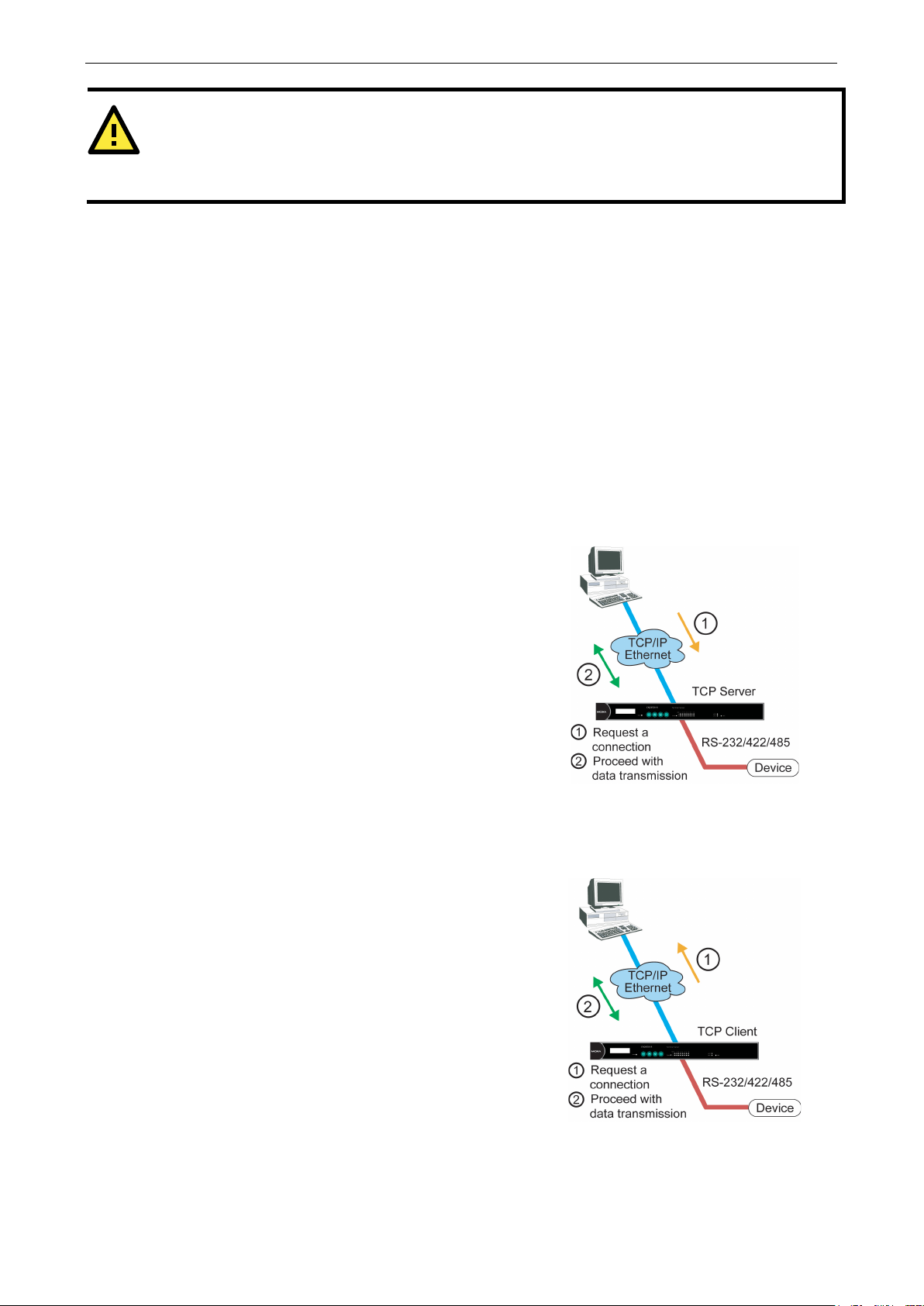
In TCP Server mode, the serial port on the CN2600 is assigned
a port number which must not conflict with any other serial
port on the CN2600. The host computer initiates contact with
the CN2600, establishes the conn ection, and receives data
from the serial device. This operation mode also supports up
to 8
collect data from the same serial device at the same time.
As illustrated in the figure, data tran smission proceeds as
follows:
The host requests a connection from th e CN2600, which is
configured for TCP
Once the connection is established, data can be transmitted in
both directions between the host and the CN2600.
In TCP Client mode, the CN2600 can actively establish a TCP
connection to a pre
arrives.
After the data has been transferred, the CN2600 can
automatically disconnect from the host computer by using the
Inactivity time settings.
As illustrated in the figure, data tran smission proceeds as
follows:
The CN2600, configured for TCP
connection from the host.
Once the connection is established, data can be transmitted in
both directions between the host and the CN2600.
System Management Set tings, for more details.
RFC2217 Mode
RFC-2217 mode is similar to Real C OM mode. That is, a driver is used to establish a transparent connection
between a host computer and a serial device by mapping the serial port on the CN2600 to a local COM port on
the host computer. RFC2217 defines general COM port control options based on the Telnet protocol. Third party
drivers supporting RFC-2217 are widely available on the Internet and can be used to implement Virtual COM
mapping to your CN2600 serial port(s).
Socket Applications
For socket applications, the CN2600 offers the following modes: TCP Server, TCP Client and UDP.
TCP Server Mode
simultaneous connections, enabling multiple hosts to
Server mode.
TCP Client Mode
-defined host computer when serial data
Client mode, requests a
Page 28

CN2600 Series Serial Port Operation Modes
4-4
Compared to TCP communication, UDP is faster and more
efficient. In UDP mode, you
unicast data
from a serial device to one or multiple host computers and the
serial device can receive data from one or multiple host
computers. These traits make UDP mode especially suited for
message display applications.
ATTENTION
If either LAN gets disconnected, it will take at least 1 minute for the LAN to reco ver after reconnecting.
If both LANs get disconnecte
transmit properly.
UDP Mode
can unicast or multi-
Redundant COM
The Redundant COM operation mode can be used to set up a redundant LAN between the serial devices
connected to the CN2600’s serial po rts and the host computer. The redundant structure involves using the
CN2600’s two LAN ports to set up two independent LANs that connect the CN2600 to the host computer. I f
either of the two LANs fails, the other LAN will continue transmitting packets between the serial devices and the
host, with the packets passing through the CN2600. In fact, one of the biggest advantages of the CN2600’s
Redundant COM mode is that the “switching time” is zero.
d, you will need to re-open your application software’s COM port for data to
Page 29

CN2600 Series Serial Port Operation Modes
4-5
NOTE
The RS
RS
connectors on the two CN2600 terminal servers will also need to use converters, such as the Moxa TCC-100I.
In this way, users can take advantage of RS
C
Dual-host Redundant Data Acquisition System (DRDAS)
The DRDAS operation mode provides a highly redundant network structure that takes advantage of the
CN2600’s dual LAN ports, dual IP addresses, and dual MAC addresses. DRDAS uses a backup PC that is set up
to take over when the primary PC fails.
The CN2600’s dual-host redundant configuration sends seria l data to 4 IP addresses on the network. U sers
select a Primary IP and 3 Secondary IPs. When the Primar y IP fails, the backup IPs take over by using the
DRDAS library.
The DRDAS library is used to configure the DRDAS of the CN series. You must use the DRDAS libr ar y to
designate the primary and secondary hosts. If you need this library, please contact conn.support@moxa.com
With this kind of redundant setup, if one of the secondary IPs tries to send commands to the serial device, the
commands are discarded by the CN2600, since only the Primary IP is allow ed to conduct bi-directional
transmission. The backup IPs are only allowed to receive data from the CN2600.
-232 connector on the Remo te Terminal Unit (RTU) show n a bove must be set up with an R S-232 to
-422/485 converter, such as the Moxa TCC-100I, to convert RS-232 signals to RS-485 signals. The
-485’s multi-drop feature to share data with the secondary
N2600.
Page 30

CN2600 Series Serial Port Operation Modes
4-6
Terminal Applications
Terminal applications involve connecting terminals to UNIX or Windows servers over a network. A terminal
connects to the appropriately configured serial port the CN2600, and the CN2600 transmit s information to and
from a UNIX or Windows server over the network through its Ethernet port. You may need to check with your
network administrator to determine the appropriate terminal mode. All terminal modes support fast keys as
used in many terminal a pplications.
Please refer to Chapter 4, Introducing Serial Port Operation Modes, for detailed information and configuration
instructions.
Terminal ASCII Mode
Terminal ASCII mode can handle up to 8 sessions per port with the ability to sw itch between sessions on the
same terminal. This mode is used for text-based terminals with no file transfer capability or encryption.
Terminal BIN Mode
Terminal BIN mode allows one session per port and is used for terminal applications that include fil e transfer
features.
Page 31

CN2600 Series Serial Port Operation Modes
4-7
Reverse Terminal Applications
Reverse terminal applications a re similar to terminal applications i n that they involve using the CN2600 to
manage the connection between a term inal and a server. The difference i s that with reverse terminal
applications, the terminal is connected through the network and the server is connected through the serial port,
rather than the other way around. In practice, a reverse terminal session typically involves a network
administrator telnetting to a device that has a dedicated serial console port used specifically for configuration
purposes.
For example, many routers, switches, UPS units, and other devices (including the CN2600) have Console/AUX
or COM ports to which a terminal can be physically connected for console management. With the CN2600, the
device’s console port can be connected to a serial port on the CN2600, allowing a network administrator to
telnet to the device remotely through the network. Although modern network equipment generally allows other
options for remote configuration through the network, there are situations in which it is necessary or desirable
to configure a device by serial console (e.g., for security reasons, when using older-generation equipment, or
as a backup configuration method when the network is down).
CN2600 reverse terminal modes al lo w the use of the CN2600 User Table or a RADIUS server for identity
verification purposes. Please refer to the Misc. Network Settings section in Chapter 8, System Management
Settings, for instructions on setting up the CN2600 User Table.
Reverse Telnet
Reverse Telnet mode is widely used for device management in telecommunication control rooms. The system
waits for a host on the network to initiate a connecti on. Since TCP Server mode does not assist with convers ion
of CR/LF commands, reverse termina l applications that require this conversion should use Reverse Telnet
mode.
Page 32

CN2600 Series Serial Port Operation Modes
4-8
Dial In/Out Modes
The CN2600 provides dial-in/dial-out access for ISPs and enterprises that need a remote access solution. When
a user at a remote site uses a PPP dial-up connection to access the CN26 00, the CN2600 plays the role of a
dial-up server, but also ensures that the user has legal access to the network b y verifying the user’s identity
with the CN2600 User Table or a RADIUS server. Please refer to the Misc. Network Settings section in Chapter
8, System Management Settings, for instructions on setting up the CN2600 User Table.
The CN2600 supports PPP, SLIP, and Terminal modes for dial-in/dial-out access. Regardless of which operating
system is used, you will always be able to use standard PPP dial-up to establish a connection. The CN2600 can
also act as a router to connect serial ports to a WAN connection. Routing protocols (including static, RIP I, and
RIP II) can be adjusted to route different WAN connections.
Please refer to Chapter 5, Configuration with Web Console, for detailed information and configuration
instructions.
Disabled Mode
You can disable any port on the CN2600 by setting the operation mode to Disabled.
Page 33

5
5. Configuration with the Web Console
The web console is the most user-friendly method available to configure the CN2600. With a standard web
browser, you have easy and intuitive access to all settings and options. In this chapter, we introduce the web
console and go through the basic configuration options. The same configuration options are also available
through the Telnet and serial console.
The following topics are covered in this chapter:
Using Your Web Browser
Browser Cookie Settings
Trusted Site Settings
Opening the Web Console
Web Console Navigation
Basic Settings
Server Settings
Time Settings
Network Settings
Basic Network Settings
Advanced Network Settings
Configuring the Rou te Table
Page 34

CN2600 Series Configuration with the Web Console
5-2
ATTENTION
If you are not using Internet Explorer, cookies are usually enabled through a web browser setting such as
“allow cookies that are stored on your computer” or “allow per
Using Your Web Browser
Browser Cookie Settings
Verify that cookies are enabled for your browser. If the cookies are disabled, you will not be able to use the web
console. (Cookies are only used for password transmission.)
1. For Internet Explorer, enable cookies by selecting Internet Options from the Tools menu:
2. Select the Privacy tab. There are six levels of privacy setting: Block All Cookies, High, Medium High,
Medium, Low, and Accept All Cookies. Users must select M e diu m High (as the image shows) or below to
access the CN2600 web console.
-session cookies.”
Page 35

CN2600 Series Configuration with the Web Console
5-3
Trusted Site Settings
For Windows 2003 users, you may need to add the CN2600’s IP address to your browser’s list of trusted sites.
1. If you see the following window while attempting to view the web console, click on Add… to modify the list
of trusted sites:
You may also directly access the list of trusted sites through Internet Options in the Tools menu of Internet
Explorer. Select the Security tab, then click on the Truste d Sit e s icon and on the Sites… button:
2. In either case, the window below should appear, showing the list of sites that you have configured Internet
Explorer to trust. Add the IP address of your CN2600 here (the factory default LAN1 IP address is
192.168.127.254 and default LAN2 IP address is 192.168.126.254.)
Page 36

CN2600 Series Configuration with the Web Console
5-4
ATTENTION
The examples and figures in this chapter use the CN2600 factory default IP address of 192.168.127.254. If you
have assigned a different IP address to your CN2600, be sure to adjust accordingly when following these
directions. Please refer to Chapter 3,
address.
ATTENTION
If you forget your password, the ONL
settings and load the factory defaults. If you have disabled th e reset button in your CN2600 configuration, you
may still use it to load the factory defaults within the first 60 second
Remember to back up your configuration by exporting it to a fi le. Your configu ration can be easily re stored by
importing the file to the CN2600. This will save time if you have forgotten the password and need to reload the
factory defaults.
After adding the CN2600’s IP address as a trusted site, you should be able to view the web console by entering
the CN2600’s IP address in your browser ’s address bar.
Opening the Web Console
Open your web browser and enter 192.168.127.254 in the website address line. This is the default IP address
for the CN2600–if a new address has been assigned, enter the new address instead. Press ENTER to load the
page.
Initial IP Address Configuration, for details on how to configure the IP
3. Enter the console password if prompted. (This will not apply if you did not enable password protection for
your CN2600.) The password will be transmitted with MD5 encryption over the Ethernet.
4. The CN2600’s web console will appear.
Y way to configure the CN2600 is by using the reset button to reset all
s that the CN2600 is powered on.
Page 37

CN2600 Series Configuration with the Web Console
5-5
Web Console Navigation
In the CN2600 web console, the left panel is the navigation panel and contains an expandable menu tree for
navigating among the various settings and categories. When you click on a menu item in the navigation panel,
the main window will display the corresponding options for that item. Configuration changes can then be made
in the main window. For example, if you click on Basic Settings in the navigation panel, the main window will
show a page of basic settings that you can configure.
You must click on the Submit button to keep your configuration changes. The Submit button will be locate d
at the bottom of every page that has configurable settings. If you navigate to another page without clicking the
Submit button, your settings will not be retained .
Changes will not take effect until they are saved and the NPort is restarted! You may complete this in
one step by clicking on the Save/Restart option after you submit a change. If you need to make several
changes before restarting, you may save your changes without restarting by selecting Save Configuration in
the navigation panel. If you restart the CN2600 without saving your configuration, the CN2600 will discard all
submitted changes.
Basic Settings
You may access Basic Settings in the navigation panel.
Server Settings
Server name: This is an optional free text field for your own use; it does not affect operation of the CN2600.
It can be used to help differentiate on e CN2600 server from another.
Server location: This is an optional free text field for your own use; it does not affect operation of the CN2600.
It is useful for assigning or describing the location of a CN2600. In a n etwork environment of multiple ser vers,
this can be a valuable aid when performing maintenance.
Time Settings
The CN2600 has a built-in Real-Time Clock for time calibration functions. Functions such as Auto Warni ng Email
or SNMP Trap can add real-time information to messages.
Before making any adjustments to the time, first select the correct time zone and submit the change. The
console will display the real time according to the time zone. To modify the real time clock, click on Modify next
to the Local time field. On ce you submit the new time, the CN2600’s firmware wil l modify the GMT time
according to your time zone and loca l time settings.
Page 38

CN2600 Series Configuration with the Web Console
5-6
ATTENTION
There is a risk of explosion if the real
The CN2600’s real time clock is powered by a lithium battery. We strongly recommend that you do not attempt
replacement of the lithium battery without help from a qualified Moxa support engineer. If you need to change
the battery, please contact the Moxa RMA service team.
Time zone (default=GMT Greenwich Mean Time): This field shows the currently selected time zone and allows
you to select a different time zone.
Local time: This field shows the time that you last opened or refreshed the browser. To set the local time for
the CN2600, click on the Modify… button, then submit your changes in the screen as shown below.
Time server: The CN2600 uses SNTP (RFC-1769) for auto time calibration. You may enter a time server IP
address or domain name in this optio na l field. Once the CN2600 is config ur ed with the c or rect time server
address, it will request time information from the time server every 10 minutes.
-time clock battery is replaced with the wrong type!
Network Settings
Basic Network Settings
You can access Basic Network Settings by expanding the Network Settings item in the navigation panel.
Basic Network Settings is where you assign the CN2600’s IP address, netmask, Gateway, and other IP
parameters.
NOTE: You must assign a valid IP address to your CN2600 before it will work in your network en vironment. Your
network system administrator should provide you with a unique IP address and related settings for your
network. First-time users can refer to Chapter 3, Initial IP Address Configuration, for more information.
Page 39

CN2600 Series Configuration with the Web Console
5-7
ATTENTION
In dynamic IP environments, the firmware will try to get the network settings from the DHCP or BOOTP server
3 times every 30 seconds until network settings are assigned by the DHCP or BOOTP server. The first try times
out after 1 second, the second after 3 seconds, and the third after 5 seconds.
If the DHCP/BOOTP server is u
netmask, and gateway settings.
IP configuration (default=Static): You can choose from four possible IP configuration modes.
Option Description
Static User-defined IP address, netmask, gateway.
DHCP DHCP server -a ss igned IP address, netmask, gateway, DNS, and time server
DHCP/BOOTP DHCP server-assigned IP address, netmask, gateway, DNS, and time server, or BOOTP
server-assigned IP address (if the DHCP server does not respond)
BOOTP BOOTP server-assigned IP address
PPPoE PPP over Ethernet, remote ISP-assigned IP address
IP Address (LAN1 default = 192.168.127.254; LAN2 default = 192. 168. 126. 254) : E n ter t h e IP address that
will be assigned to your CN2600. All ports on the CN2600 will share this IP address. An IP address is a number
assigned to a network device (such as a computer) as a permanent address on the network. Computers use the
IP address to identify and talk to each other over the network. Choose a proper I P addre ss tha t is unique and
valid in your network environment.
Netmask (default=255.255.255.0): Enter the subnet mask. A subnet mask represents all of the network hosts
at one geographic location, in one building, or on the same local area network. When a packet is sent out over
the network, the CN2600 will use the subnet mask to check whether the desired TCP/IP host specified in the
packet is on the local network segment. If the address is on the same network segment as the CN2600, a
connection is established directly from the CN2600. Otherwise, the connection is established through the given
default gateway
Gateway: Enter the IP address of the gateway if applicable. A gateway is a network computer that acts as an
entrance to another network. Usually, the computers that control traffic within the network or at the local
Internet service provider are gateway nodes. The CN2600 needs to know the IP address of the default gateway
computer in order to communicate with the hosts outside the local network environment. For correct gateway
IP address information, consult the network administrator.
navailable, the firmware will use the default IP address (192.168.127.254),
DNS server 1: This is an optional field. If your network has access to a DNS server, you may enter the DNS
server’s IP address in this field. This allows the CN2600 to use domain names instead of IP addresses to access
hosts.
Domain Name System (DNS) is the way that Internet domain names are identified and translated into IP
addresses. A domain name is an alphanumeric name, such as www.moxa.com, that it is usually easier to
remember than the numeric IP address. A DNS server is a host that translates this kind of text-based domain
name into the actual IP address used to establish a TCP/IP connection. When the user wants to visit a particular
website, the user’s computer sends the domain name (e.g., www.moxa.com) to a DNS server to request that
website’s numeric IP address. When the IP address is received from the DNS server, the user’s computer uses
that information to connect to the website’s web server.
The CN2600 will play the role of a DNS client, in the sense that it will actively query the DNS server for the IP
address associated with a particular domain name. The following functions on the CN2600 web console support
the use of domain names in place of IP addresses: Time Server, Destination IP Address (in TCP Client mode),
Mail Server, SNMP Trap Server, Destination Address (in Pair Connection mode), Primary/Secondary Host
Address (in Terminal mode), RADIUS Server and SMTP Server.
DNS server 2: This is an optional field. The IP address of another DNS server may be entered in this field for
times when DNS server 1 is unavailabl e.
Page 40

CN2600 Series Configuration with the Web Console
5-8
PPPoE user account and PPPoE password: For dynamic broadband networks such as xDSL or cable modem,
users must enter the username and password that they received from their ISP to establish network connection.
If a serial port on the CN2600 will be using PPPoE, enter the account name an d p a ssword in these fields.
WINS function (default=enable): Enable or disable the WINS (Windows Internet Naming Service) serv er.
WINS server: If a WINS Server is connected to the network, enter the WINS Server’s IP address in this field.
TCP/IP uses IP addresses to identify hosts, but users often use symbolic names, such as computer names. The
WINS Server, which uses NetBIOS over T C P/IP, contains a dynamic database to map computer names to IP
addresses.
LAN speed (default=Auto): You may configure the network speed for the built-in Ethernet connection on the
CN2600. IEEE802.3 Ethernet supports auto negotiation of transfer speed. However, some switches/hubs
require that the communication speed be fixed at 100Mbps or 10Mbps.
Advanced Network Settings
You can access Advanced Network Settings by expanding the Network Settings item in the navigation panel.
Advanced Network Settings is where the routing protocol and gratuitous ARP are configured.
What is RIP?
RIP (Routing Information Protocol) is a protocol used to manage routing information within a self-contained
network, such as a corporate LAN (Local Area Network) or an interconnected group of such LANs.
By using RIP, a gateway host with a ro uter can send its entire routing table, which lists all the other hosts it
knows about, to its closest neighbor host every 30 seconds. The neighbor host in turn will pass this information
on to its closest neighbor, and so on, until all hosts within the ne twork have the same routing path information.
This state is known as network convergence. RIP uses a hop count as a way of determining network distance.
(Other protocols use more sophisticated algorithms that also include timing.) After receiving a packet headed
for a specific destination, a network host with a router uses the routing table information to determine the next
host to route the packet to.
RIP is considered an effective solution for small homogeneous networks. For larger, more complicated
networks, transmitting the entire routing table every 30 seconds can bog down the network with a lot of extra
traffic.
RIP 2 is an extension of RIP. Its purpose is to expand the amount of useful information contained in RIP packets,
and to add security elements. RIP 2 has become the standard version of RIP, and the original RIP is no longer
used.
Routing Protocol: You may select which routing protocol, if any, your network will employ.
Gratuitous ARP: In some applications, you may n eed the CN2600 to send broadcast packets to update the
ARP table on the server. If you enable this function and set the send period, the CN2600 will send periodically
send broadcast packets at the specified time interval.
Page 41

CN2600 Series Configuration with the Web Console
5-9
ATTENTION
When a serial port is configured for PPP/SLIP, the Iface field must be set to that serial port for proper
comm
Configuring the Route Table
You can access the Route Table by expanding System Management and then Misc. Network Settings in
the navigation panel. The route table is where you configure how the CN2600 will connect to an outside
network.
You are allowed up to 32 entries in the route table. For each entry, you must provide information on the
gateway, destination, netmask, metric hops, and interface.
Gateway: This is the IP address of the next-hop router.
Destination: This is the host ’s IP address or the network address of the route’s destination.
Netmask: This is the destination network’ s netmask.
Metric: Enter the number of hops from the source to the destinationto allow the CN2600 to prioritize the
routing of data packets if more than one router is available.
Iface: This is the network interface to which the packet must be sent.
unication.
Page 42

CN2600 Series Configuration with the Web Console
5-10
Configuring Routes to the Internet
In this example, the Notebook PC dia ls into the CN2600 to request a connection to the Internet host at
210.48.96.9, which is not on the local network 203.67.6.xxx. This causes the CN2600 to act as a router and
send the datagram to the default next-hop router, 203.67.6.254. In this case, we should add the gateway IP
address of 203.67.6.254 to the routing table to ha n dle hops to 210.48.96.9.
Generally, connections to the Internet are handled by assigning a gateway server in the network settings rather
than through the route table.
Page 43

CN2600 Series Configuration with the Web Console
5-11
Configuring Routes to the Intranet
In this example, dial-in users can make requests to Intranet hosts 202.65.66.4 or 202.65.66.5, which are on
network 202.65.66.xxx (located outside network 203.67.6.xxx). You will need to add a route entry for the
next-hop router, 203.67.6.252 that delivers requests to network 202.65.66.xxx. The metric hop in this case
is 2 route hops.
Page 44

CN2600 Series Configuration with the Web Console
5-12
Configuring Multiple-Point Routes
For multi-location enterprises, CN2600 servers can be placed in different branch offices and used as bo th
multi-point routers and as remote access servers. When hosts (e.g., the Web/FTP and E-mail/News s ervers
shown in the figure) send requests to hosts on another network, such as 202.6.6.xxx or 201.2.2.xxx, the
corresponding CN2600 delivers the request to the another CN2600 on the remote end, 202.6.6.254 or
201.2.2.254, as the next-hop router..
For this example, assume that Modem 1 is connected to serial port 1, Modem 2 is connected to serial port 2, and
PPP source and destination IP addresses of modems 1, 2, 3, and 4 are as follow s:
Source IP Destination IP Source IP Destina t ion IP
Modem 1 203.67.6.250 202.6.6.250 Modem 3 202.6.6.250 203.67.6.250
Modem 2 203.67.6.249 201.2.2.249 Modem 4 201.2.2.249 203.67.6.249
In this case, you will need to add two entries to the routing table, as shown in the following figure.
Page 45

6
6. Configuring Serial Port Operation Modes
In this chapter, we explain how to configure the individual serial port modes.
The following topics are covered in this chapter:
Port Setting Basics
Device Control Applications
Real COM Mode
RFC2217 Mode
Socket Applications
TCP Server Mode
TCP Client Mode
UDP Mode
Redundant COM
DRDAS
DRDAS Real COM
DRDAS TCP Server
Terminal Applications
Terminal ASCII (TERM_ASC)
Terminal BIN (TERM_BIN)
Reverse Terminal
Dial In/Out Applications
PPP Mode
PPPD Mode
SLIP Mode
SLIPD Mode
Dynamic Mode
Disabled Mode
Page 46

CN2600 Series Configuring Serial Port Operation Modes
6-2
Port Setting Basics
Each serial port on the CN2600 can be configured independently. To configure the operation mode and settings
for a port, expand Serial Port Settings in the navigation p a nel, then expand the port that you would like to
configure. Individual port settings are grouped into four c ategories in the navi gation panel: Operati on Modes,
Communication Parameters, Data Buffering/Log, and Modem Settings.
Select Operation Modes in the navigation panel to select and configure the mode for each serial port. For
CN2600 models with 2 or more serial ports, you may use the checkboxes at the bottom of the window to apply
the settings to one or more ports.
Application: Select an application for the serial port from among the choices. Your application will determine
the modes that are available.
Mode: Once you have chosen an application, select the mode. The available configuration settings will vary
depending on the mode that you have s elected.
Page 47

CN2600 Series Configuring Serial Port Operation Modes
6-3
ATTENTION
When Max connection is greater than 1, the CN2600 will use a multi connection application (i.e., 2 to 8 hosts
are allowed access to the port at the same time). When using a multi connection application, the CN2600 will
use the serial communication par a meters as defined here in the web console, and all hosts connected to the
port must use identical serial settings. If one of the hosts opens the COM port with different serial settings, data
will not be transmitted properly.
Device Control Applications
Real COM Mode
multiple hosts’ Real COM drivers open the port at the same time, the COM driver only provides a pure data
tunnel—no control ability. The serial port parameters will use firmware settings instead of depending on your
application program (AP).
Application software that is based on the COM driver w ill receive a driver response of “success” when the
software uses any of the Win32 API functions. The firmware will only send data back to the driver on the host.
Data will be sent first-in-first-out when data comes into the CN2600 from the Ethe rnet interface.
Ignore jammed IP (default=No): This option determines how the port will proceed if multiple hosts are
connected and one or more of the hosts stops responding as the port is transmitting data. If you select No, the
port will wait until the data has been transmitted successfully to all hosts before transmitting the next group of
data. If you select Yes, the port will ignore the host that stopped responding and continue data transmission
to the other hosts.
Allow driver control (default=No): This option determines how the port will proceed if driver control
commands are received from multiple hosts that are connected to the port. If No is selected, driver control
commands will be ignored. If Yes is selected, control commands will be accepted, with the most re cent
command received taking precedence.
Connection goes down (default=always high): You can configure what happens to the RTS and DTR signals
when the Ethernet connection goes down. For some applications, serial devices need to know the Ethernet link
status through RTS or DTR signals sent through the ser ial port. Use goes low if you want the RTS and DTR
signal to change their state to low wh en the Ethernet connection goes down. Use always high if you do not
want the Ethernet connection status to affect the RT S or DTR signals.
Page 48

CN2600 Series Configuring Serial Port Operation Modes
6-4
ATTENTION
In order to enable a delimiter, packet length must be set to 0. Delimiter 2 should only be enabled in conjunction
with Delimiter 1 and never on its own; otherwise there may be data errors. Even when a delimiter is enabled,
the CN2600 will still pack and send the data when the amount of data exc eeds 1 KB.
Packet length (default=0): The Packet length setting refers to the maximum amount of data that is allowed
to accumulate in the serial port buffer before sending. At the default of 0 for packet length, no maximu m
amount is specified and data in the buffer will be sent as specified by the delimiter settings or when the buffer
is full. When a packet length betw een 1 and 1024 bytes is specified, data in t h e b uffer will be sent as soon it
reaches the specified length.
Delimiter 1 and Delimiter 2 (default=None): When Delimiter 1 is enabled, the serial port will clear the buffer
and send the data to the Ethernet port when a specific character, entered in hex format, is received. A second
delimiter character may be enabled and specified in the Delimiter 2 field, so that both characters act as the
delimiter to control when data shou ld b e sent.
Delimiter process (default=Do Nothing): The Delimiter process field determines how the data is handled
when a delimiter is received. Delimiter 1 must be enabled for this field to have effect. If Delimiters 1 and 2 are
both enabled, both characters must be received for the delimiter process to take place.
• Do Nothing: Data in the buffer will be tr a nsmitted when the delimiter is r eceived.
• Delimiter + 1: Data in th e buffer will be tran s mitted after 1 additional byte is received following the
delimiter.
• Delimiter + 2: Data in the buffer will be transmitted after 2 additional bytes are received following the
delimiter.
• Strip Delimiter: Data in the buffer is first stripped of the delimiter befor e being transmitted.
Force transmit (default=0 ms): This parameter defines how large a gap in serial communication the CN2600
will allow before packing the serial data in its internal buffer for network transmission.
As data is received through the serial port, it is stored by the CN2600 in t he internal buffer. The CN2600
transmits data stored in the buffer via TCP/IP, but only when the internal buffer is full or as specified by the
force transmit time. When set to 0, the force transmit time is disabled, and transmission is determined solely
by the data in the internal buffer. At 1 to 65535, the TCP/IP protocol software will pack the serial data received
after there is a gap in serial communication that exceeds the specified force transmit time.
The optimal force transmit time depends on your application, but it must be at least larger than one character
interval within the specified baudrate. For example, assume that the serial port is set to 1200 bps, 8 data bits,
1 stop bit, and no parity. In this case, the total number of bits needed to send a character is 10 bits, and the
time required to transfer one character is
(10 (bits) / 1200 (bits/s)) × 1000 (ms/s) = 8.3 ms.
Therefore, you should set the force transmit time to be larger than 8.3 ms, so in this case, it must be greater
than or equal to 10 ms.
If it is necessary to send a series of characters in the same packet, the serial device will need to send that series
of characters within the specified force transmit time, and the total length of data must be less than or equal
to the CN2600’s internal buffer size (1 KB per port).
Page 49

CN2600 Series Configuring Serial Port Operation Modes
6-5
ATTENTION
In order to enable a delimiter, packet length must be set to 0. Delimiter 2 should only be enabled in conjunction
with Delimiter 1 and never on its own; otherwise there may be data errors. Even when a delimiter is enabled,
the CN2600 will still pack and send the data when the amount of data exc eeds 1 KB.
RFC2217 Mode
TCP alive check time (de fault=7 min): This field specifies how long the CN2600 will wait for a response to
“keep alive” packets before closing the TCP connection. The CN2600 checks connection status by sending
periodic “keep alive” packets. If the remote host does not respond to the packet within the time specified in this
field, the CN2600 will force the existing TCP connection to close. For socket and device control modes, the
CN2600 will listen for another TCP connection from another host after closing the connection. If TCP alive
check time is set to 0, the TCP connect ion will remain open even if there is no response to the “keep alive”
packets.
TCP port (default=4001): This is the TCP port number assignment for the serial port on the CN2600. It is the
port number that the serial port uses to listen to connections, and that other devices must use to contact the
serial port. To avoid conflicts with well known TCP ports, the default is set to 4001.
Packet length (default=0): The Packet length setting refers to the maximum amount of data that is allowed
to accumulate in the serial port buffer before sending. At the default of 0 for packet length, no maximum
amount is specified and data in the buffer will be sent as specified by the delimiter settings or when the buffer
is full. When a packet length betw een 1 and 1024 bytes is specified, data in t h e b uffer will be sent as soon it
reaches the specified length.
Delimiter 1 and Delimiter 2 (default=None): When Delimiter 1 is enabled, the serial port will clear the buffer
and send the data to the Ethernet port when a specific character, entered in hex format, is received. A second
delimiter character may be enabled and specified in the Delimiter 2 fi eld, so that both characters act as the
delimiter to indicate when data should be sent.
Delimiter process (def a ult=Do Nothing): The Delimiter pr ocess field determines how the data is handled
when a delimiter is received. Delimiter 1 must be enabled for this field to have effect. If Delimiters 1 and 2 are
both enabled, both characters must be received for the delimiter process to take place.
• Do Nothing: Data in the buffer will be tr a nsmitted when the delimiter is r eceived.
• Delimiter + 1: Data in the buffer will be tran s mitted after 1 additional byte is received following the
delimiter.
• Delimiter + 2: Data in the buffer will be transmitted after 2 additional bytes are received following the
delimiter.
• Strip Delimiter: Da t a in the buffer is first stripped of th e d elimiter before being transmit ted.
Page 50

CN2600 Series Configuring Serial Port Operation Modes
6-6
Force transmit (default=0 ms): This parameter defines how large a gap in serial communication the CN2600
will allow before packing the serial data in its internal buffer for network transmission.
As data is received through the serial port, it is stored by the CN2600 in t he internal buffer. The CN2600
transmits data stored in the buffer via TCP/IP, but only when the internal buffer is full or as specified by the
force transmit time. When set to 0, the force transmit time is disabled, and transmission is determined solely
by the data in the internal buffer. At 1 to 65535, the TCP/IP protocol software will pack the serial data received
after there is a gap in serial communication that exceeds the specified force transmit time.
The optimal force transmit time depends on your application, but it must be at least larger than one character
interval within the specified baudrate. For example, assume that the serial port is set to 1200 bps, 8 data bits,
1 stop bit, and no parity. In this case, the total number of bits needed to send a character is 10 bits, and the
time required to transfer one charac ter is
(10 (bits) / 1200 (bits/s)) × 1000 (ms/s) = 8.3 ms.
Therefore, you should set the force transmit time to be larger than 8.3 ms, so in this case, it must be greater
than or equal to 10 ms.
If it is necessary to send a series of characters in the same packet, the serial device will need to send that series
of characters within the specified force transmit time, and the total length of data must be less than or equal
to the CN2600’s internal buffer size (1 KB per port).
Socket Applications
TCP Server Mode
TCP alive check time (de fault=7 min): This field specifies how long the CN2600 will wait for a response to
“keep alive” packets before closing the TCP connection. The CN2600 checks connection status by sending
periodic “keep alive” packets. If the remote host does not respond to the packet within the time specified in this
field, the CN2600 will f orce the existing TCP connec tio n to close. For socket and device contr ol modes, the
CN2600 will listen for another TCP connection from another host after closing the connection. If TCP alive
check time is set to 0, the TCP connection will remain open even if there is no response to the “keep alive”
packets.
Page 51

CN2600 Series Configuring Serial Port Operation Modes
6-7
ATTENTION
If used, the Inactivity time setting should be greater than the Force transmit time. To prevent the unintended
loss of data due to the session being disconnected, it is highly recommended that this value is set large enough
so that the intended data transfer is co m
ATTENTION
In order to enable a delimiter, packet length must be set to 0. Delimiter 2 should only be enabled in conjunction
with Delimiter 1 and never on its own; otherwise there may be data errors. Even when a delimiter is enabled,
the CN2600 will s
Inactivity time (default=0 ms): This field specifies how long the CN2600 will wait for incoming and outgoing
data through the serial port before closing the TCP connection. The TCP connection is closed if there is no
incoming or outgoing data through the serial port for the specified Inactivity time. If this field is set to 0, the
TCP connection is kept active until a connection close request is rece ived.
pleted.
Max connection (default=1): This field is used if you need to receive data from different hosts simultaneously.
When set to 1, only a single host may open the TCP c onnection to the serial port. Wh en set to 2 or greater, u p
to the specified number of hosts may open this port at the same time. When multiple hosts establish a T C P
connection to the serial port at the same time, the CN2600 will duplicate the serial data and transmit it to all
the hosts. Ethernet data is sent on a first-in first-out basis to the serial port when data comes into the CN2600
from the Ethernet interface.
Ignore jammed IP (default=No): This option determines how the port will proceed if multiple hosts are
connected and one or more of the hosts stops responding as the port is transmitting data. If you select No, the
port will wait until the data has been transmitted successfully to all hosts before transmitting the next group of
data. If you select Yes, the port will ignore the host that stopped responding and continue data transmission
to the other hosts.
Allow driver control (default=No): This option determines how the port will proceed if driver control
commands are received from multiple hosts that are connected to the port. If No is selected, driver control
commands will be ignored. If Yes is selected, control comma nd s will be accepted, with the most re cent
command received taking precedence.
TCP port (default=4001): This is the TCP port number assignment for the serial port on the CN2600. It is the
port number that the serial port uses to listen to connections, and that other devices must use to contact the
serial port. To avoid conflicts with well known TCP ports, the default is set to 4001.
Command port (default=966): The Command port is the TCP port for listening to SSDK commands from the
host. In order to prevent a TCP port conflict with other applications, the user can set the Command port to
another port if needed.
Packet length (default=0): The Packet length setting refers to the maximum amount of data that is allowed
to accumulate in the serial port buffer before sending. At the default of 0 for packet length, no maximum
amount is specified and data in the buffer will be sent as specified by the delimiter settings or when the buffer
is full. When a packet length betw een 1 and 1024 bytes is specified, data in the buffer will be sent as soon it
reaches the specified length.
Delimiter 1 and Delimiter 2 (default=None): When Delimiter 1 is enabled, the serial port will clear the buffer
and send the data to the Ethernet port when a specific character, entered in hex format, is received. A second
delimiter character may be enabled and specified in the Delimiter 2 fi eld, so that both characters act as the
delimiter to indicate when data should be sent.
till pack and send the data when the amount of data exceeds 1 KB.
Delimiter process (def a ult=Do Nothing): The Delimiter pr ocess field determines how the data is handled
when a delimiter is received. Delimiter 1 must be enabled for this field to have effect. If Delimiters 1 and 2 are
both enabled, both characters must be received for the delimiter process to take place.
• Do Nothing: Data in the buffer will be tr a nsmitted when the delimiter is r eceived.
Page 52

CN2600 Series Configuring Serial Port Operation Modes
6-8
• Delimiter + 1: Data in th e buffer will be tran s mitted after 1 addit ional byte is received following the
delimiter.
• Delimiter + 2: Data in the buffer will be transmitted after 2 additional bytes are received following the
delimiter.
• Strip Delimiter: Data in the buffer is first stripped of the delimiter before being transmitted.
Force transmit (default=0 ms): This parameter defines how large a gap in serial communication the CN2600
will allow before packing the serial data in its internal buffer for network transmission.
As data is received through the serial port, it is stored by the CN2600 in the internal buffer. The CN2600
transmits data stored in the buffer via TCP/IP, but only when the internal buffer is full or as specified by the
force transmit time. When set to 0, the force transmit time is disabled, and transmission is determined solely
by the data in the internal buffer. At 1 to 65535, the TCP/IP protocol software will pack the serial data received
after there is a gap in serial communication that exceeds the specified force transmit time.
The optimal force transmit time depends on your application, but it must be at least larger than one character
interval within the specified baudrate. For example, assume that the serial port is set to 1200 bps, 8 data bits,
1 stop bit, and no parity. In this case, the total number of bits needed to send a character is 10 bits, and the
time required to transfer one charac ter is
(10 (bits) / 1200 (bits/s)) × 1000 (ms/s) = 8.3 ms.
Therefore, you should set the force transmit time to be larger than 8.3 ms, so in this case, it must be greater
than or equal to 10 ms.
If it is necessary to send a series of characters in the same packet, the serial device will need to send that series
of characters within the specified force transmit time, and the total length of data must be less than or equal
to the CN2600’s internal buffer size (1 KB per port).
TCP Client Mode
TCP alive check time (de fault=7 min): This field specifies how long the CN2600 will wait for a response to
“keep alive” packets before closing the TCP connection. The CN2600 checks connection status by sending
periodic “keep alive” packets. If the remote host does not respond to the packet within the time specified in this
field, the CN2600 will force the existing TCP connection to close. For socket and device control modes, the
Page 53

CN2600 Series Configuring Serial Port Operation Modes
6-9
ATTENTION
Inactivity time should at least be set larger than that of Force transmit time. To prevent the unintended loss of
data due to the session being disconnected, it is highly recommended that this value is set large enough so that
the intended data transfer is completed.
ATTENTION
Inactivity time is O NL Y ac
ATTENTION
Up to 4 connections can be establis h ed between the CN2600 and hosts. The con n ection speed or throughput
may be low if any one of the four connections is slow, since the one slow connection will slow down the other
3 connections.
ATTENTION
The Destination IP address parame ter can be the IP address, domain name, or the name defined in the host
table. For some applications, the user may need to send the data actively to the r emote des
name.
CN2600 will listen for another TCP connection from another host after closing the connection. If TCP alive
check time is set to 0, the TCP connect io n will remain open even if there is no re sp onse to the “keep alive”
packets.
Inactivity time (default=0 ms): This field specifies how long the CN2600 will wait for incoming and outgoing
data through the serial port before closing the TCP connection. The TCP connection is closed if there is no
incoming or outgoing data through the serial port for the specified Inactivity time. If this field is set to 0, the
TCP connection is kept active until a connection close request is rece ived.
Ignore jammed IP (default=No): This option determines how the port will proceed if multiple hosts are
connected and one or more of the hosts stops responding as the port is transmitting data. If you select No, the
port will wait until the data has been transmitted successfully to all hosts before transmitting the next group of
data. If you select Yes, the port will ignore the host that stopped responding and continue data transmission
to the other hosts.
Destination address 1 through 4 (default=None): Specifying an IP address allows the CN2600 to connect
actively to the remote host. At least one destination must be provided.
TCP port (default=4001): This is the TCP port number assignment for the serial port on the CN2600. It is the
port number that the serial port uses to listen to connections, and that other devices must use to contact the
serial port. To avoid conflicts with well known TCP ports, the default is set to 4001.
tive when Connection Control (s ee below) is set to Any character/Inactivity time.
Designated local port 1 through 4 (default=5010 through 5013): Use these fields to specify the designated
local ports.
Connection control (default=Startup/None): This setting determines the parameters under which a TCP
connection is establish ed or disconnected. The different options are given in the following tabl e. In general,
both the Connect condition and Disconnect conditions are given.
Option Description
Startup/None (default) A TCP connection will be established on startup, and will remain active indefinitely.
Any Character/None A TCP connection will be established when any character is received from the serial
interface, and will re m ain active indefinitely.
tination domain
Page 54

CN2600 Series Configuring Serial Port Operation Modes
6-10
A TCP connection will be established when a DSR “On” signal is received, and will
ATTENTION
In order to enable a delimiter, packet length must be set to 0. Delimiter 2 should only be enabled in conjunction
with Delimiter 1 and never on its own; otherwise there may be data errors. Even when a delimiter is enabled,
the CN2600 will still pack an
Option Description
Any Character/
Inactivity Time
DSR On/DSR Off
DSR On/None A TCP connection will be established when a DSR signal of NPort is “On”, and will
DCD On/DCD Off A TCP connection will be established when a DCD “On” signal is received, and will
DCD On/None A TCP connection will be established when a DCD “On” signal is received, and will
Packet length (default=0): This field refers to the maximum amount of data that is allowed to accumulate in
the serial port buffer before sending. At the default of 0 for packet length, no maximum amount is specified and
data in the buffer will be sent as specified by the delimiter settings or when the buffer is full. When a packet
length between 1 and 1024 bytes is specifi ed, data in the buffer will be sent as soon it reaches the specified
length.
Delimiter 1 and Delimiter 2 (default=None): When Delimiter 1 is enabled, the serial port will clear the buffer
and send the data to the Ethernet port when a specific character, entered in hex format, is received. A second
delimiter character may be enabled and specified in the Delimiter 2 fi eld, so that both characters act as the
delimiter to indicate when data should be sent.
A TCP connection will be established when any character is received from the serial
interface, and will be disconnected when Inactivity time is reached.
be disconnected when a DSR “Off” signal is received.
remain active indefinitely.
be disconnected when a DCD “Off” signal is rece i ved.
remain active indefinitely.
d send the data when the amount of data exceeds 1 KB.
Delimiter process (default=Do Nothing): The Delimiter process field determines how the data is handled
when a delimiter is received. Delimiter 1 must be enabled for this field to have effect. If Delimiters 1 and 2 are
both enabled, both characters must be received for the delimiter process to take place.
• Do Nothing: Data in the buffer will be tr a nsmitted when the delimiter is r eceived.
• Delimiter + 1: Data in the buffer will be transmitted after 1 additional byte is received following the
delimiter.
• Delimiter + 2: Data in the buffer will be transmitted after 2 additional bytes are received following the
delimiter.
• Strip Delimiter: Data in the buffer is first stripped of the delimiter befor e being transmitted.
Force transmit (default=0 ms): This parameter defines how large a gap in serial communication the CN2600
will allow before packing the serial data in its internal buffer for network transmission.
As data is received through the serial port, it is stored by the CN2600 in the internal buffer. The CN2600
transmits data stored in the buffer via TCP/IP, but only when the internal buffer is full or as specified by the
force transmit time. When set to 0, the force transmit time is disabled, and transmission is determined solely
by the data in the internal buffer. At 1 to 65535, the TCP/IP protocol software will pack the serial data received
after there is a gap in serial communication that exceeds the specified force transmit time.
The optimal force transmit time depends on your application, but it must be at least larger than one character
interval within the specified baudrate. For example, assume that the serial port is set to 1200 bps, 8 data bits,
1 stop bit, and no parity. In this case, the total number of bits needed to send a character is 10 bits, and the
time required to transfer one charac ter is
(10 (bits) / 1200 (bits/s)) × 1000 (ms/s) = 8.3 ms.
Therefore, you should set the force transmit time to be larger than 8.3 ms, so in this case, it must be greater
than or equal to 10 ms.
Page 55

CN2600 Series Configuring Serial Port Operation Modes
6-11
ATTENTION
The maximum selectable IP address range is 64 addresses. However, when using multi-unicast, you may enter
IP addresses of the form xxx.xxx.xxx.255 in the Begin field. For example, enter 192.127.168.255 to all ow the
CN2600 to broadcast UDP packets to all hosts with IP addresses between 192.127.168.1 and
192.127.168.254.
ATTENTION
In order to enable a delimiter, packet length must be set to 0. Delimiter 2 should only be enabled in conjunction
with Delimiter 1 and never on its own; otherwise there may be data errors. Even when a delimiter is enabled,
the CN2600 will still pack and send the data when the amount of data exc eeds 1 KB.
If it is necessary to send a series of characters in the same packet, the serial device will need to send that series
of characters within the specified force transmit time, and the total length of data must be less than or equal
to the CN2600’s internal buffer size (1 KB per port).
UDP Mode
Destination address 1 through 4 (default=None): In UDP mode, you may specify up to 4 ranges of IP
addresses for the serial port to connect to. At least one destination range must be provided.
Local listen port (default=4001): This is the UDP port that the CN2600 listens to and that other devices must
use to contact the CN2600 . To avoid conflicts with well known UDP ports, the default is set to 4001.
Packet length (default=0): The Packet length setting refers to the maximum amount of data that is allowed
to accumulate in the serial port buffer before sending. At the default of 0 for packet length, no maximum
amount is specified and data in the buffer will be sent as specified by the delimiter settings or when the buffer
is full. When a packet length betw een 1 and 1024 bytes is specified, data in t h e b uffer will be sent as soon it
reaches the specified length.
Delimiter 1 and Delimiter 2 (default=None): When Delimiter 1 is enabled, the serial port will clear the buffer
and send the data to the Ethernet port when a specific character, entered in hex format, is received. A second
delimiter character may be enabled and specified in the Delimiter 2 field, so that both characters act as the
delimiter to indicate when data should be sent.
Delimiter process (defau lt=Do Nothing): The Delimiter process field determines how the data is handled
when a delimiter is received. Delimiter 1 must be enabled for this field to have effect. If Delimiters 1 and 2 are
both enabled, both characters must be received for the delimiter process to take place.
• Do Nothing: Data in the buffer will be tr a nsmitted when the delimiter is r eceived.
Page 56

CN2600 Series Configuring Serial Port Operation Modes
6-12
• Delimiter + 1: Data in th e buffer will be tran s mitted after 1 additional byte is received following the
delimiter.
• Delimiter + 2: Data in the buffer will be transmitted after 2 additional bytes are received follow ing the
delimiter.
• Strip Delimiter: Data in the buffer is first stripped of the delimiter before being transmitted.
Force transmit (default=0 ms): This parameter defines how large a gap in serial communication the CN2600
will allow before packing the serial data in its internal buffer for network transmission.
As data is received through the serial port, it is stored by the CN2600 in t he internal buffer. The CN2600
transmits data stored in the buffer via TCP/IP, but only when the internal buffer is full or as specified by the
force transmit time. When set to 0, the force transmit time is disabled, and transmission is determined solely
by the data in the internal buffer. At 1 to 65535, the TCP/IP protocol software will pack the serial data received
after there is a gap in serial communication that exceeds the specified force transmit time.
The optimal force transmit time depends on your application, but it must be at least larger than one character
interval within the specified baudrate. For example, assume that the serial port is set to 1200 bps, 8 data bits,
1 stop bit, and no parity. In this case, the total number of bits needed to send a character is 10 bits, and the
time required to transfer one character is
(10 (bits) / 1200 (bits/s)) × 1000 (ms/s) = 8.3 ms.
Therefore, you should set the force transmit time to be larger than 8.3 ms, so in this case, it must be greater
than or equal to 10 ms.
If it is necessary to send a series of characters in the same packet, the serial device will need to send that series
of characters within the specified force transmit time, and the total length of data must be less than or equal
to the CN2600’s internal buffer size (1 KB per port).
Redundant COM
Max connection (default=1): This field is used if you need to receive data from different hosts simultaneously.
When set to 1, only one specific host can access this port of the CN2600, and the Redundant COM driver on that
host will have full control over the port. When set to 2 or greater, up to the specified number of hosts’
Redundant COM drivers may open this port at the same time. When multiple hosts’ Redundant COM drivers
open the port at the same time, the COM driver only provides a pure data tunnel—no control ability. The serial
port parameters will use firmware settings instead of depending on your application program (AP).
Application software that is based o n the COM driver will receive a driver response of “success” when the
software uses any of the Win32 API functions. The firmware will only send data back to the driver on the host.
Data will be sent first-in-first-out when data comes i n to the CN2600 from the Ethernet interface.
Page 57

CN2600 Series Configuring Serial Port Operation Modes
6-13
ATTENTION
When Max connection is greater than 1, the CN2600 will use a multi connection application (i.e., 2 to 4 hosts
are allowed access to the port at the same time). When using a multi connection application, the CN2600 will
use the serial communication par a meters as defined here in the web con sole, and all hosts connected to the
port must use identical serial settings. If one of the hosts opens the COM port with different serial settings, data
will not be transmitted properly.
ATTENTION
In order to enable a delimiter, packet length must be set to 0. Delimiter 2 should only be enabled in conjunction
with Delimiter 1 and never on its own; otherwise there may be data errors. Even when a delimiter is enabled,
the CN2600 will still pack and send the data when the amount of data exc eeds 1 KB.
Ignore jammed IP (default=No): This option determines how the port will proceed if multiple hosts are
connected and one or more of the hosts stops responding as the port is transmitting data. If you select No, the
port will wait until the data has been transmitted successfully to all hosts before transmitting the next group of
data. If you select Yes, the port will ignore the host that stopped responding and continue data transmission
to the other hosts.
Allow driver control (default=No): This option determines how the port will proceed if driver control
commands are received from multiple hosts that are connected to the port. If No is selected, driver control
commands will be ignored. If Yes is selected, control commands will be accepted, with the most recent
command received taking precedence.
Connection goes down (default=always high): You can configure what happens to the RTS and DTR signals
when the Ethernet connection goes down. For some applications, serial devices need to know the Ethernet link
status through RTS or DTR signals sent through the ser ial port. Use goes low if you want the RTS and DTR
signal to change their state to low wh en the Ethernet connection goes down. Use always high if you do not
want the Ethernet connection status to affect the RT S or DTR signals.
Packet length (default=0): The Packet length setting refers to the maximum amount of data that is allowed
to accumulate in the serial port buffer before sending. At the default of 0 for packet length, no maximum
amount is specified and data in the buffer will be sent as specified by the delimiter settings or when the buffer
is full. When a packet length betw een 1 and 1024 bytes is specified, data in the buffer will be sent as soon it
reaches the specified length.
Delimiter 1 and Delimiter 2 (default=None): When Delimiter 1 is enabled, the serial port will clear the buffer
and send the data to the Ethernet port when a specific character, entered in hex format, is received. A second
delimiter character may be enabled and specified in the Delimiter 2 fi eld, so that both characters act as the
delimiter to control when data should be sent.
Delimiter process (def a ult=Do Nothing): The Delimiter pr ocess field determines how the data is handled
when a delimiter is received. Delimiter 1 must be enabled for this field to have effect. If Delimiters 1 and 2 are
both enabled, both characters must be received for the delimiter process to take place.
• Do Nothing: Data in the buffer will be transmitted wh en the delimiter is received.
• Delimiter + 1: Data in th e buffer will be tran s mitted after 1 additional byte is received following the
delimiter.
• Delimiter + 2: Data in the buffer will be transmitted after 2 additional bytes are received following the
delimiter.
• Strip Delimiter: Data in the buffer is first stripped of the delimiter before being transmitted.
Force transmit (default=0 ms): This parameter defines how large a gap in serial communication the CN2600
will allow before packing the serial data in its internal buffer for network transmission.
Page 58

CN2600 Series Configuring Serial Port Operation Modes
6-14
DRDAS
DRDAS Real COM
TCP alive check time (de fault=7 min): This field specifies how long the CN2600 will wait for a response to
“keep alive” packets before closing the TCP connection. The CN2600 checks connection status by sending
periodic “keep alive” packets. If the remote host does not respond to the packet within the time specified in this
field, the CN2600 will force the existing TCP connection to close. For socket and device control modes, the
CN2600 will listen for another TCP connection from another host after closing the connection. If TCP alive
check time is set to 0, the TCP connection will remain open and will not send any “keep alive” packets.
Ignore jammed IP (default=No): This option determines how the port will proceed if multiple hosts are
connected and one or more of the hosts stops responding as the port is transmitting data. If you select No, the
port will wait until the data has been transmitted successfully to all hosts before transmitting the next group of
data. If you select Yes, the port will ignore the host that stopped responding and continue data transmission
to the other hosts.
Primary IP address The primary host’s IP address.
If left blank, then every host on the netw ork cannot access the serial port.
Backup 1 IP address Backup host’s IP address
Backup 2 IP address Backup host’s IP address
Backup 3 IP address Backup host’s IP address
Connection goes down (default=always high): You can configure what happens to the RTS and DTR signals
when the Ethernet connection goes down. For some applications, serial devices need to know the Ethernet link
status through RTS or DTR signals sent through the ser ial port. Use goes low if you want the RTS and DTR
signal to change their state to low when the Ethernet connection goes down. Use always high if you do not
want the Ethernet connection status to affect the RT S or DTR signals.
Packet length (default=0): The Packet length setting refers to the maximum amount of data that is allowed
to accumulate in the serial port buffer before sending. At the default of 0 for packet length, no maximum
amount is specified and data in the buffer will be sent as specified by the delimiter settings or when the buffer
is full. When a packet length betw een 1 and 1024 bytes is specified, data in the buffer will be sent as soon it
reaches the specified length.
Delimiter 1 and Delimiter 2 (default=None): When Delimiter 1 is enabled, the serial port will clear the buffer
and send the data to the Ethernet port when a specific character, entered in hex format, is received. A second
Page 59

CN2600 Series Configuring Serial Port Operation Modes
6-15
ATTENTION
In order to enable a delimiter, packet length must be set to 0. Delimiter 2 should only be enabled in conjunction
with Delimiter 1 and never on its own; otherwise there may be data errors. Even when a delimiter is enabled,
the CN2600 will still pack and send the data when
delimiter character may be enabled and specified in the Delimiter 2 fi eld, so that both characters act as the
delimiter to control when data should be sent.
the amount of data exceeds 1 KB.
Delimiter process (def a ult=Do Nothing): The Delimiter pr ocess field determines how the data is handled
when a delimiter is received. Delimiter 1 must be enabled for this field to have effect. If Delimiters 1 and 2 are
both enabled, both characters must be received for the delimiter process to take place.
• Do Nothing: Data in the buffer will be tr a nsmitted when the delimiter is r eceived.
• Delimiter + 1: Data in th e buffer will be tran s mitted after 1 additional byte is received following the
delimiter.
• Delimiter + 2: Data in the buffer will be transmitted after 2 additional bytes are received following the
delimiter.
• Strip Delimiter: Data in the buffer is first stripped of the delimiter befor e being transmitted.
Force transmit (default=0 ms): This parameter defines how large a gap in serial communication the CN2600
will allow before packing the serial data in its internal buffer for network transmission..
As data is received through the serial port, it is stored by the CN2600 in the internal buffer. The CN2600
transmits data stored in the buffer via TCP/IP, but only when the internal buffer is full or as specified by the
force transmit time. When set to 0, the force transmit time is disabled, and transmission is determined solely
by the data in the internal buffer. At 1 to 65535, the TCP/IP protocol software will pack the serial data received
after there is a gap in serial communication that exceeds the specified force transmit time.
The optimal force transmit time depends on your application, but it must be at least larger than one character
interval within the specified baudrate. For example, assume that the serial port is set to 1200 bps, 8 data bits,
1 stop bit, and no parity. In this case, the total number of bits needed to send a character is 10 bits, and the
time required to transfer one charac ter is
(10 (bits) / 1200 (bits/s)) × 1000 (ms/s) = 8.3 ms.
Therefore, you should set the force transmit time to be larger than 8.3 ms, so in this case, it must be greater
than or equal to 10 ms.
If it is necessary to send a series of characters in the same packet, the serial device will need to send that series
of characters within the specified force transmit time, and the total length of data must be less than or equal
to the CN2600’s internal buffer size (1 KB per port).
Page 60

CN2600 Series Configuring Serial Port Operation Modes
6-16
DRDAS TCP Server
TCP alive check time (de fault=7 min): This field specifies how long the CN2600 will wait for a response to
“keep alive” packets before closing the TCP connection. The CN2600 checks connection status by sending
periodic “keep alive” packets. If the remote host does not respond to the packet within the time specified in this
field, the CN2600 will force the existing TCP connection to close. For socket and device control modes, t he
CN2600 will listen for another TCP connection from another host after closing the connection. If TCP aliv e
check time is set to 0, the TCP connection will remain open even if there is no resp onse to the “keep alive”
packets.
Inactivity time (default=0 ms): This field specifies how long the CN2600 will wait for incoming and outgoing
data through the serial port before closing the TCP connection. The TCP connection is closed if there is no
incoming or outgoing data through the serial port for the specified Inac tivity time. If this field is set to 0, the
TCP connection is kept active until a connection close request is rece ived.
Ignore jammed IP (default=No): This option determines how the port will proceed if multiple hosts are
connected and one or more of the hosts stops responding as the port is transmitting data. If you select No, the
port will wait until the data has been transmitted successfully to all hosts before transmitting the next group of
data. If you select Yes, the port will ignore the host that stopped responding and continue data transmissio n
to the other hosts.
Primary IP address The primary host’s IP address.If left blank, then every host on the network cannot access
the serial port.
Backup 1 IP address Backup host’s IP address
Backup 2 IP address Back up ho st’s IP address
Backup 3 IP address Backup host’s IP address
TCP Port TCP data port number Via the data port, users can retrieve data through the async line. TCP port
command port number Via the command port, users can issue commands across the network to set the line’s
configuration parameters, such as baudrate, data bits, flow control condition, etc.
Connection goes down (default=always high): You can configure what happens to the RTS and DTR signals
when the Ethernet connection goes down. For some applications, serial devices need to know the Ethernet link
Page 61

CN2600 Series Configuring Serial Port Operation Modes
6-17
ATTENTION
In order to enable a delimiter, packet length must be set to 0. Delimiter 2 should only be enabled in conjunction
with Delimiter 1 and never on its own; otherwise there may be data errors. Even when a delimiter is enabled,
the CN2600 will still pack and send the data when the amount of data exc eeds 1 KB.
status through RTS or DTR signals sent through the ser ial port. Use goes low if you want the RTS and DTR
signal to change their state to low when the Ethernet connection goes down. Use always high if you do not
want the Ethernet connection status to affect the RT S or DTR signals.
Packet length (default=0): The Packet length setting refers to the maximum amount of data that is allowed
to accumulate in the serial port buffer before sending. At the default of 0 for packet length, no maximu m
amount is specified and data in the buffer will be sent as specified by the delimiter settings or when the buffer
is full. When a packet length betw een 1 and 1024 bytes is specified, data in t h e b uffer will be sent as soon it
reaches the specified length.
Delimiter 1 and Delimiter 2 (default=None): When Delimiter 1 is enabled, the serial port will clear the buffer
and send the data to the Ethernet port when a specific character, entered in hex format, is received. A second
delimiter character may be enabled and specified in the Delimiter 2 field, so that both characters act as the
delimiter to control when data should b e sent.
Delimiter process (default=Do Nothing): The Delimiter process field determines how the data is handled
when a delimiter is received. Delimiter 1 must be enabled for this field to have effect. If Delimiters 1 and 2 are
both enabled, both characters must be received for the delimiter process to take place.
• Do Nothing: Data in the buffer will be tr a nsmitted when the delimiter is r eceived.
• Delimiter + 1: Data in th e buffer will be tran s mitted after 1 additional byte is received following the
delimiter.
• Delimiter + 2: Data in the buffer will be transmitted after 2 additional bytes are received following the
delimiter.
• Strip Delimiter: Data in the buffer is first stripped of the delimiter befor e being transmitted.
Force transmit (default=0 ms): This parameter defines how large a gap in serial communication the CN2600
will allow before packing the serial data in its internal buffer for network transmission.
As data is received through the serial port, it is stored by the CN2600 in t he internal buffer. The CN2600
transmits data stored in the buffer via TCP/IP, but only when the internal buffer is full or as specified by the
force transmit time. When set to 0, the force transmit time is disabled, and transmission is determined solely
by the data in the internal buffer. At 1 to 65535, the TCP/IP protocol software will pack the serial data received
after there is a gap in serial communication that exceeds the specified force transmit time.
The optimal force transmit time depends on your application, but it must be at least larger than one character
interval within the specified baudrate. For example, assume that the serial port is set to 1200 bps, 8 data bits,
1 stop bit, and no parity. In this case, the total number of bits needed to send a character is 10 bits, and the
time required to transfer one character is
(10 (bits) / 1200 (bits/s)) × 1000 (ms/s) = 8.3 ms.
Therefore, you should set the force transmit time to be larger than 8.3 ms, so in this case, it must be greater
than or equal to 10 ms.
If it is necessary to send a series of characters in the same packet, the serial device will need to send that series
of characters within the specified force transmit time, and the total length of data must be less than or equal
to the CN2600’s internal buffer size (1 KB per port).
Page 62

CN2600 Series Configuring Serial Port Operation Modes
6-18
ATTENTION
Inactivity time should at least be set larger than that of Force transmit time. To prevent the unintended loss of
data due to the session being disconnected, it is highly recommended that this value is set large enough such
that the intended data transfer is completed.
Terminal Applications
Terminal ASCII (TERM_ASC)
TCP alive check time (de fault=7 min): This field specifies how long the CN2600 will wait for a response to
“keep alive” packets before closing the TCP connection. The CN2600 checks connection status by sending
periodic “keep alive” packets. If the remote host does not respond to the packet within the time specified in this
field, the CN2600 will force the existing TCP connection to close. For socket and device control modes, the
CN2600 will listen for another TCP connection from another host after closing the connection. If TCP alive
check time is set to 0, the TCP connect ion will remain open even if there is no response to the “keep alive”
packets.
Inactivity time (default=0 min): This field specifies how long the CN2600 will wait for incoming and outgoing
data through the serial port before closing the TCP connection. The TCP connection is closed if there is no
incoming or outgoing data through the serial port for the specified Inactivity time. If this field is set to 0, the
TCP connection is kept active until a connection close request is rece ived.
Auto-Link Protocol: If this field is se t to None, the CN2600 will not connect to the host automatically. If
Auto-Link Protocol is set to Telnet or Rlogin, the CN2600 will connect to the host automatically us in g the
specified protocol.
Primary and Secondary host address: If spec if ied, the fields designate permanent h osts to which the
terminal will always be connected.
Telnet TCP port (default=23): By default, the Telnet TCP port number is set to 23, which is the default T CP
port number for Telnet.
Terminal type (default=ansi): Some older terminal applications may require that the terminal type be
transmitted before the connection can be established. You may need to refer to the server’s documentation to
Page 63

CN2600 Series Configuring Serial Port Operation Modes
6-19
determine the appropriate terminal type. For most applications, this setting will be unnecessary and will have
no effect
Max. Sessions (default=4): This setting allows you to configure the maximum. number of sessions allowed for
the serial port.
Change Session (default=(^T)0x 14): This field defines the quick key to change a session.
Quit (default=(^E)0x05): This field defines the quick key to quit a session.
Break: This field defines the quick key to send a break signal.
Interrupt: This field defines the quick key for program termination.
Authentication type (default=None): This field allows you to configure the method used, if any, to verify a
user’s ID and authorization.
Option Description
Local Verify the ID against the CN2600 User Table.
RADIUS Verify the ID against the external RADIUS server.
None Authentication is not required.
Auto-login prompt (defaul t= o gin :)
Password prompt (default= as swo rd:)
Login user name: Enter the terminal login ID here.
Login password: Enter the password for the terminal login here.
Terminal BIN (TERM_BIN)
Terminal Binary mode can be used to transfer files with XMODEM or ZMODEM. You are only allowed to open one
terminal session at a time when in Terminal Binary mode.
TCP alive check time (de fault=7 min): This field specifies how long the CN2600 will wait for a response to
“keep alive” packets before closing the TCP connection. The CN2600 checks connection status by sending
periodic “keep alive” packets. If the remote host does not respond to the packet within the time specified in this
field, the CN2600 will force the existing TCP connection to close. For socket and device control modes, t he
CN2600 will listen for another TCP connection from another host after closing the connection. If TCP alive
Page 64

CN2600 Series Configuring Serial Port Operation Modes
6-20
ATTENTION
Inactivity time should at least be set larger than that of Force transmit time. To prevent the unintended loss of
data due to the session being disconnected, it is highly recommended that this value is set large enough so that
the intended data transfer is completed.
check time is set to 0, the TCP connect ion will remain open even if there is no response to the “keep alive”
packets.
Inactivity time (default=0 min): This field specifies how long the CN2600 will wait for incoming and outgoing
data through the serial port before closing the TCP connection. The TCP connection is closed if there is no
incoming or outgoing data through the serial port for the specified Inactivity time. If this field is set to 0, the
TCP connection is kept active until a connection close request is rece ived.
Auto-Link Protocol: If this field is se t to None, the CN2600 will not connect to the host automatically. If
Auto-Link Protocol is set to Telnet or Rlogin, the CN2 600 will connect to the host automatically using the
specified protocol.
Primary and Secondary host address: If spec if ied, the fields designate permanent h osts to which the
terminal will always be connected.
Telnet TCP port (default=23): By default, the Telnet TCP port number is set to 23, which is the default TCP
port number for Telnet.
Terminal type (default=ansi): Some older terminal applications may require that the terminal type be
transmitted before the connection can be established. You may need to refer to the server’s documentation to
determine the appropriate terminal type. For most applications, this setting will be unnecessary and will have
no effect
Quit (default=(^E) 0x05): This field configures the quick key used to disconnect the link between the current
terminal session and the remote host. It is not necessary for binary communication.
Authentication type (default=None): This field allows you to configure the method used, if any, to verify a
user’s ID and authorization.
Option Description
Local Verify the ID against the CN2600 User Table.
RADIUS Verify the ID against the external RADIUS server.
None Authentication is not required.
Auto-login prompt (defa u lt=ogin:)
Password prompt (default=assword:)
Login user name: Enter the terminal login ID here.
Login password: Enter the password for the terminal login here.
Page 65

CN2600 Series Configuring Serial Port Operation Modes
6-21
Reverse Terminal
TCP alive check time (de fault=7 min): This field specifies how long the CN2600 will wait for a response to
“keep alive” packets befo r e closing the TCP connection. The CN2 600 checks connection status by sending
periodic “keep alive” packets. If the remote host does not respond to the packet within the time specified in this
field, the CN2600 will force the existing TCP connection to close. For socket and device control modes, the
CN2600 will listen for another TCP connection from another host after closing the connection. If TCP alive
check time is set to 0, the TCP connection will remain open even if there is no response to the “keep alive”
packets.
Inactivity time (default=0 min): This field specifies the idle time setting for auto-disconnection. A setting of
0 min. will cause the port to remain conn ected even if idle.
TCP port (default=4001): This is the TCP port number assignment for the serial port on the CN2600. It is the
port number that the serial port uses to listen to connections, and that other devices must use to contact the
serial port. To avoid conflicts with well known TCP ports, the default is set to 4001.
Authentication type (default=None): This field allows you to configure the method used, if any, to verify a
user’s ID and authorization.
Option Description
Local Verify the ID against the CN2600 User Table.
RADIUS Verify the ID against the external RADIUS server.
None Authentication is not required.
Map keys <CR-LF> (default=CR-LF): This specifies how the ENTER key is mapped from the Ethernet port
through the serial port.
Option Description
<CR-LF> carriage return + line feed (i.e., th e cursor will jump to the next line, and
return to the first character of the line)
<CR> carriage return (i.e., the cursor w ill return to the first character of the line)
<LF> line feed (i.e., the cursor will jump to the next line, but not move horizontally)
Page 66

CN2600 Series Configuring Serial Port Operation Modes
6-22
Dial In/Out Applications
PPP Mode
PPP provides standard PPP service for both dial-in and dial-out.
Destination IP address: This is the IP address of the remote dial -in/ dial-out server.
Source IP address: The Source IP address is IP address assigned to this serial port.
IP netmask: The IP netmask defines the netmask, also known as the subnet mask, for the PPP connection
TCP/IP compression (default=No): The setting of this field depend s on whether the remote user’s
application requests compres sio n.
Inactivity time (default=0 ms): This field specifies the idle time setting for auto-disconnection. A setting of 0
ms will cause the port to remain conne cted even if idle.
Link quality report (default=No): Settin g this field to Yes allows the CN2600 to disconnect a connection if the
link noise exceeds a certain thresh old.
Outgoing PAP ID: This is the dial-out user I D account.
PAP password: This is the dial-out user password.
Incoming PAP check (default=None): This field allows you to configure the method used, if any, to verify a
user’s ID and authorization.
Option Description
Local Verify the ID against the CN2600 User Table.
RADIUS Verify the ID against the external RADIUS server.
None Authentication is not required.
Disconnect by (default=None): If this field is set as DCD-off, the connection will be disconnected when the
DCD signal is off. If this field is set as DSR-off, the connection will be disconnected when the DSR signal is off.
Page 67

CN2600 Series Configuring Serial Port Operation Modes
6-23
PPPD Mode
PPPD (PPP on demand) is used for dial-in services, since it provides PPP services only when receiving a request
from a remote PC.
Destination IP address: This is the IP address of the remote dial -in/ dial-out server.
Source IP address: The Source IP address is IP address assigned to this serial port.
IP netmask: The IP netmask defines the netmask, also known as the subnet mask, for the PPP connection
TCP/IP compression (default=No): The setting of this field depend s on whether the remote user’s
application requests compres sio n.
Inactivity time (default=0 ms): This field specifies the idle time setting for auto-disconnection. A setting of 0
ms will cause the port to remain conne cted even if idle.
Link quality report (default=No): Settin g this field to Yes allows the CN2600 to disconnect a connection if the
link noise exceeds a certain threshold.
Outgoing PAP ID: This is the dial-out user I D account.
PAP password: This is the dial-out user password.
Incoming PAP check (default=None): This field allows you to configure the method used, if any, to verify a
user’s ID and authorization.
Option Description
Local Verify the ID against the CN2600 User Table.
RADIUS Verify the ID against the external RADIUS server.
None Authentication is not required.
Disconnect by (default=None): If this field is set as DCD-off, the connection will be disconnected when the
DCD signal is off. If this field is set as DSR-off, the connection will be disconnected when the DSR signal is off.
Page 68

CN2600 Series Configuring Serial Port Operation Modes
6-24
SLIP Mode
SLIP provides standard SLIP service for both dial-in and dial-out.
Destination IP address: This is the IP address of the remote dial -in/ dial-out server.
Source IP address: The Source IP address is IP address assigned to this serial port.
IP netmask: The IP netmask defines the netmask, also known as the subnet mask, for the SL I P connection
TCP/IP compression (default=No): The setting of this field depend s on whether the remote user’s
application requests compres sio n.
Inactivity time (default=0 ms): This field specifies the idle time setting for auto-disconnection. A setting of 0
ms will cause the port to remain conne cted even if id le.
Disconnect by (default=None): If this field is set as DCD-off, the connection will be disconnected when the
DCD signal is off. If this field is set as DSR-off, the connection will be disconnected when the DSR signal is off.
Page 69

CN2600 Series Configuring Serial Port Operation Modes
6-25
SLIPD Mode
SLIPD (SLIP on demand) is used for dial-in services, since it provides SLIP services only when receiving a
request from a remote PC.
Destination IP address: This is the IP address of the remote dial -in/ dial-out server.
Source IP address: The Source IP address is IP address assigned to this serial port.
IP netmask: The IP netmask defines the netmask, also known as the subnet mask, for the SL I P connection
TCP/IP compression (default=No): The setting of this field depend s on whether the remote user’s
application requests compres sio n.
Inactivity time (default=0 ms): This field specifies the idle time setting for auto-disconnection. A setting of 0
ms will cause the port to remain conne cted even if idle.
Disconnect by (default=None): If this field is set as DCD-off, th e connection will be disconnected when the
DCD signal is off. If this field is set as DSR-off, the connection will be disconnected when the DSR signal is off.
Page 70

CN2600 Series Configuring Serial Port Operation Modes
6-26
Dynamic Mode
Dynamic mode integrates PPPD, SLIPD, and T e rminal dial-in services. Dynamic mode automatically detect s
which remote connection mode is being used, and provides corresponding services. You can individua lly
enable/disable PPP/SLIP/Term inal services by selecting Yes or No next to the corresponding option. Yes will
enable that type of service; No will disable it.
Authentication type (default=None): This field allows you to configure the method used, if any, to verify a
user’s ID and authorization.
Option Description
Local Verify the ID against the CN2600 User Table.
RADIUS Verify the ID against the external RADIUS server.
None Authentication is not required.
Disabled Mode
When the Application is set to Disable, the relevant port will be disabled.
Page 71

7
7. Additional Serial Port Settings
In this chapter, we describe additional serial port settings on the CN2600. The same configuration options are
also available through the telnet and serial console.
The following topics are covered in this chapter:
Port Communication Parameters
Serial Parameters
Port Data Buffering/Log
Port Modem Settings
Welcome Message
Page 72

CN2600 Series Additional Serial Port Settings
7-2
ATTENTION
The serial parameters for the each serial port on the CN2600 should matc h the parameters used by the
connected serial device.
appropriate serial communication parameters.
ATTENTION
If the port requires a special baudra te that is not listed, such as 500000 b p s, y ou may can select the Other
option and enter the desired bau
supported baudrate. The margin for error will be less than 1.7% for all baudrates under 921600 bps.
Port Communication Parameters
Port alias: This optional fie ld allows you to assign an alias to a port for easier identification.
Serial Parameters
Baud rate (default=115200 bps): This field configures the port’s baudrate. Select one of the standard
baudrates from the dropdown box, or select Other and then type the desired baudrate in the input box.
Data bits (default=8): This field configures the data bits parameter. Note: If data bits is set to 5 bits, stop bits
will automatically b e set to 2 bits.
Stop bits (default=1): This field configures the stop bits parameter. Note: If data bits is set to 5 bits, stop bits
will automatically b e set to 1.5 bits.
Parity (default=None): This f ield configures the parity parameter.
You may need to refer to your serial device’s user’s manual to determine the
drate into the text box. The CN2600 wi ll automatically calculate the closest
Flow control (default=RTS/CTS): This field configures the flow control type.
FIFO (default=Enable): This field enables or disables the 128-byte FIFO buffer. The CN2600 provides FIFO
buffers for each serial port, for both the Tx and Rx signals. Note, however, that you should disable the port’s
FIFO setting if the attached serial device does not have a FIFO buffer of its own. This is because a serial device
that does not have its own buffer may not be able to keep up with data sent from the CN2600’s FIFO buffer.
Interface (default=RS-232): You may configure the serial interface to RS-232, RS-422, RS-485 2-wire, or
RS-485 4-wire.
Page 73

CN2600 Series Additional Serial Port Settings
7-3
Port Data Buffering/Log
The CN2600 supports port buffering to prevent the loss of serial data when the Ethernet connection is down.
Port buffering can be used in TCP Server mode, TCP Client mode, and Pair Connection mode. For other modes,
the port buffering settings will have no effect.
Port buffering enable (default=No): You may enable port buffering by setting this field to Yes.
Serial data logging enabl e (d ef a ult=No): If this field is set to Yes, the CN2600 will store data logs on the
system RAM for all serial ports. Note that this data is not saved when the CN2600 is powered off. Each serial
port is allotted 128 KB to store that port’s log file.
Port Modem Settings
Modem settings are used for the Dial In/Out modes. These settings will have no effect on ports configured for
other modes.
Enable modem (default=Disable)
Initial string: Use this field to configure the initial string that the modem will use to establish the connection.
For example, AT&S0=1 for auto-answer.
Dial up: Use this field to configure the modem’s Dial -up AT command string.
Phone number: Use this field to configure the number that the user uses to dial out.
Page 74

CN2600 Series Additional Serial Port Settings
7-4
Welcome Message
You can enable and enter a welcome message to greet dial-in or terminal users. For ports configured for other
modes, the welcome message will not apply.
Page 75

8
8. System Management Settings
In this chapter, we describe additional server settings on the CN2600. The same configuration options are also
available through the telnet and serial cons ole.
The following topics are covered in this chapter:
Misc. Network Settings
Accessible IP List
SNMP Agent Settings
DDNS
Host Table
User Table
Authentication Server
System Log Settings
Auto Warning Settings
Event Settings
Serial Event Setting s
E-mail Alert
SNMP Trap
Maintenance
Console Setting
Ping
Firmware Upgrade
Configurating Import/Export
Load Factory Defaults
Change Password
Certificate
Ethernet SSL Certificate Import
Certificate/Key De l ete
System Monitoring
Serial to Network Connections
Serial Port Status
Serial Port Error Count
Serial Port Settings
Network Connections
Network Statistics
Serial Data Log
System Log
Routing
Save Configuration
Restart
Restart System
Restart Ports
Page 76

CN2600 Series System Management Settings
8-2
Misc. Network Settings
Accessible IP List
The CN2600 uses an IP address-based f iltering method to control access to its serial ports.
The Accessible IP list allows you restrict network access to the CN2600 . Access is controlled by IP address.
When the accessible IP list is enabled, a host’s IP address must be listed in order to have access to the CN2600.
You may add a specific address or range of addresses by using a combination of IP address and netmask, as
follows:
To allow access to a specific IP address
Enter the IP address in the correspo n ding field; enter 255.255.255.255 for the netmask.
To allow access to hosts on a specific subnet
For both the IP address and netmask, use 0 for the last digit (e.g., 192.168.1.0 and 255.255.255.0).
To allow unrestricted access
Deselect the Enable the accessible IP list option.
Refer to the following table for more configuration examples.
Allowed hosts Entered IP address/Netmask
Any host Disable
192.168.1.120 192.168.1.120 / 255.255.255.255
192.168.1.1 to 192.168.1.254 192.168.1.0 / 255.255.255.0
192.168.0.1 to 192.168.255.254 192.168.0.0 / 255.255.0.0
192.168.1.1 to 192.168.1.126 192.168.1.0 / 255.255.255.128
192.168.1.129 to 192.168.1.254 192.168.1.128 / 255.255.255.128
Page 77

CN2600 Series System Management Settings
8-3
ATTENTION
The Accessible IP List will not be used if you configure the seri al port for DRDAS Real COM mode or DRDAS TCP
Server mode. In this case, the Primary IP address, three Backup IP addresses, and filtering method from the
DRDAS configuration will be used.
SNMP Agent Settings
SNMP: To enable the SNMP Agen t fu nction, select the Enable option, an d enter a community name (e.g.,
public).
Read community string (default=public): Th is is a text password mechanism that is used to weakly
authenticate queries to agents of mana ged network devices.
Write community string (default=private): This is a text password mechanism that is used to weakly
authenticate changes to agents of managed network devices.
Contact name: The optional SN MP contact information usually includes an emergency contact name and
telephone or pager number.
Location: Use this optional field to specify the location string for SNMP agents such as the CN2600. This string
is usually set to the street address w h er e the CN2600 is physically locate d.
SNMP agent version: The CN2600 supports SNMP V1, V2, and V3.
Read-only and Read/write access control
The following fields allow you to define user names, passwords, and authenti cation pa ramete rs for tw o levels
of access: read-only and read/write. The name of the field will indicate which level of access it refers to. For
example, Read only authen tication mode allows you to configur e the authentication mode for read -only
access, whereas Read/write a u thentication mode allows you to configure the authentication mode for
read/write access. For each level of access, you may configure the following:
User name: Use this optional field to identify the user name for the specified lev el of access.
Page 78

CN2600 Series System Management Settings
8-4
Authentication mode (default=Disable): Use this field to select MD5 o r SHA as the method of password
encryption for the specified lev el o f a ccess, or to disable authentication
Privacy mode (default=Disable): Use this field to enable to disable DES_CBC data encryption for the specified
level of access.
Password: Use this field to set the password for the specified level of access.
Privacy: Use this field to defi ne the encryption key for the specified level of access
DDNS
Please refer t to Appendix C, Dynamic Domain Name Server, for information on setting up DDNS on your
CN2600.
Host Table
The Host Table may be used to simplify IP address entry on the CN2600 console by assigning a Host Name to
a Host IP Address. When you assign a Host Name to a Host IP Address, you may then use the Host Name for
some fields on the console rather tha n entering the IP address. Up to 16 entries can be stored on the Host
Table.
Page 79

CN2600 Series System Management Settings
8-5
User Table
The CN2600 User Table may be used for to a uthenticate users for terminal or rever se terminal access and is
useful if you do not have an external RADIUS server for authentication. The CN2600 Use r Table stores up to 64
entries, with fields for User Name, Password, and Phone Number.
Authentication Server
RADIUS server IP: If you are using a RADIUS server for user authentication, enter its IP address here.
Page 80

CN2600 Series System Management Settings
8-6
RADIUS key: If you are using a RADIUS server for user authentication, enter its password here.
UDP port (default=1645): If you are using a RADIUS server, enter its UDP port assignment here.
RADIUS accounting: Use this field to enable or disable RADIUS accounting.
System Log Settings
System Log Settings allows the administrator to customize which netwo rk events are logged by the CN2600.
Events are grouped into four categories, known as event grou ps, and the administrator selects which groups to
log under Local Log. The actual system events that would be logged for each system group are listed under
summary. For example, if System was enabled, then System Cold Start events and Power Down events (for
2AC model) would be logged.
Group Event
System System Cold Start, System Warm Start, Power Down
Network DHCP/BOOTP/PPPoE Get IP/Renew, NTP, Mail Fail, NTP Connect Fail, DHCP Fail, IP Conflict ,
Ethernet Link Down
Config Login Fail, IP Changed, Password Changed, Config Changed, Firmware Upgrade, SSL Key
Import, Config Import, Config Export
OpMode Connect, D isconnect, Authentication Fail, Restart
Auto Warning Settings
Event Settings
Page 81

CN2600 Series System Management Settings
8-7
On the Event Settings page, you may configure how administrators are notified of certain system, network, and
configuration events. Depending on the event, different options for automatic notification are available, as
shown above. Mail refers to sending an e-mail to a specified address. Trap refers to sending an SNMP Trap.
Cold start: This refers to starting the system from a power off state, or after upgrading your firmware
Warm start: This refers to restarting the CN2600 without turning the pow er off.
Power down: Power1 and Power2 refer to the built-in power jacks. If either power fails, the CN2600 will
attempt to send an e-mail warning.
Network Event: Ethernet1 and Ethernet2 refer to the built-in Ethernet ports. These settings configure the
CN2600 to change the status of the relay output and alarm LED if the specified connection goes down.
Console(web/text) login auth fail: This field refers to a failed attempt to log in to a password- protected
CN2600 console.
IP changed: With this option selected, the CN2600 will attempt to se n d an e-mail warning before it reboots
after an IP address change. However, the CN2600 will reboot with the new IP address regardless of whether or
not the e-mail transmission is suc ce ss fu l.
Password changed: With th i s option selected, the CN2600 will attempt to send an e-mail warning before it
reboots with a new console password. If the CN2600 is unable to send an e-mail message to the mail server
within 15 seconds, it will still r eb oot without sending the e-mail.
Serial Event Settings
On the Serial Event Settings page, you may configure how administrators are notified of each serial port’s
DCD and DSR changes. Mail refers to sending an e-mail to a specific address. Trap refers to sending an SNMP
Trap.
DCD changed
A change in the DCD (Data Carrier Detect) signal indicates that the modem connection status has changed. For
example, if the DCD signal changes to low, it indicates that the connection line is down. When the DCD signal
changes to low, the CN2600 will automatically send a warning to the administrator as configured on the Serial
Event Settings page.
DSR changed
A change in the DSR (Data Set Ready) signal indicates that the data communication equipment is powered off.
For example, if the DSR signal changes to low, it indicates that the data communication equipment is powered
down. When the DSR signal changes to low, the CN2600 will automatically send a warning to the administrator
as configured on the Serial Event Settings page.
Page 82

CN2600 Series System Management Settings
8-8
ATTENTION
SNMP indicates a change in DCD or DSR signals but does not differentiate between the two. A change in either
signal from “
” is indicated by “link
down.”
ATTENTION
Consult your Network Administrator or ISP for the proper mail server settings. The Aut o warning function may
not work properly if it is not configured
CRAM
E-mail Alert
–” to “+” is indicated by “link up” and a change in either signal from “+” to “–
The E-mail Alert settings configure how e-mail warnings are sent for system and serial port events. You may
configure up to 4 e-mail addresses to receive automatic warnings.
-MD5 (RFC 2554).
Mail server: This field is for your mail server’s domain name or IP address.
User name: This field is for your mail server’s user name, if required.
Password: This field is for your mail server’s password, if required.
From e-mail address: This is the e-mail ad dress from which automatic e-mail warnings will be sent.
To e-mail address 1 to 4: This is the e-mail address or addresses to which the automatic e-mail warnings will
be sent.
correctly. The CN2600’s SMTP AUTH supports LOGIN, PLAIN, and
Page 83

CN2600 Series System Management Settings
8-9
SNMP Trap
SNMP trap server IP: Use this field to indicate the IP address to use for receiving SNMP traps.
Trap version (default=v2): Use this field to select the SNMP trap version.
Trap community (default=public):Use this field to designate the S NMP trap community.
Maintenance
Console Setting
On this screen, access to different C N2600 configuration console options (HTTP, HTTPS, Telnet, SSH) can b e
enabled or disabled. The CN2600 front panel, known as the LCM (Liquid Crystal Module), may be configured for
read-only or writeable access. In other words, you can use the front panel to check console settings only (read
only access) or to actually make changes to the settings (writeable acces s). Note that if the console is
password-protected and LCM is configured for writeable access, you will need to enter the password to submit
any console setting changes. Please refer to Change Password later in this chapter for more information on
passwords. Finally, you may also enable or disable the reset button.
Page 84

CN2600 Series System Management Settings
8-10
Ping
You can ping an IP address from the CN2600 web console in order to test the Ethernet connection . Enter the
IP address or domain name in the Destination field to mak e su re that the connection is OK.
Firmware Upgrade
The CN2600’s firmware can be upgraded though the web console, serial console, or through NPor t Search
Utility. If you have made any changes to your configuration, remember to save the configuration first before
upgrading the firmware. Please refer to Save Configuration later in this chapter for more information. Any
unsaved changes will be discarded when the firmware is upgraded. To upgrade the firmware, simply enter the
file name and click Submit. The latest firmware can be downloaded at www.moxa.com
.
Page 85

CN2600 Series System Management Settings
8-11
Configurating Import/Export
The CN2600 can share or back up its configuration by exporting all settings to a file, which can then be
imported into another CN26 00.
To import a configuration, go to System Management Maintenance Configuration Import. Enter the
configuration file path/name and click Submit. The CN2600’s configuration settings will be updated according
to the configuration file. If you also wish to import the IP configuration (i.e., the CN2600’s IP address, netmask,
gateway, etc.), make sure that Import all configurations incl uding IP configuratio ns is checked off.
To export a configuration, go to System Management Maintenance Configuration Export and click
Download. A standard download window will appear, and you will be able to download the configuration into
a file name and location of your choice.
Page 86

CN2600 Series System Management Settings
8-12
ATTENTION
If you forget the password, the ONLY way to configure the CN2600 is by using the reset button on the CN2600’s
casing to load the factor
Before you set a password for the first time, it is a good idea to export the configuration to a file when you have
finished setting up your CN2600. Your configuration can then be easily imported back into the CN2600 if you
need to reset the C
Configuration Import/Export earlier in this chapter for more details.
Load Factory Defaults
This function will reset all of CN2600’s settings to the factory default values. All previous settings including the
console password will be lost. If you wish to keep the CN2600 IP address, netmask, and other IP settings, make
sure Keep IP settings is checked off before loading the factory defaults.
Change Password
For all changes to the CN2600’s password protection settings, you will first need to enter the old password.
Leave this blank if you are setting up password prote ction for the first time. To set up a new password or change
the existing password, enter your desired password under both New password and Confirm password. To
remove password protection, leave the New password and Confirm password boxes blank.
y defaults.
N2600 due to a forgotten password or for other reasons. Please refer to the section on
Page 87

CN2600 Series System Management Settings
8-13
Certificate
Ethernet SSL Certificate Import
Certificate/Key Delete
System Monitoring
Serial to Network Connections
Go to Serial to Network Connections under Serial Status to view the operation mode and status of each
connection, for each serial port. All monitor functions will refresh automatically every 5 seconds.
Page 88

CN2600 Series System Management Settings
8-14
Serial Port Status
Go to Serial Port Status under Serial Status to view the current status of each serial port.
Serial Port Status Buffering
Monitor port buffering usage (bytes) of each serial port.
Serial Port Error Count
Go to Serial Port Error Count under Serial St a tus to view the error count for each serial port.
Serial Port Settings
Go to Serial Port Settings under Serial Status to view a summary of the settings for each serial port.
Page 89

CN2600 Series System Management Settings
8-15
Network Connections
Go to Network Connections under System Status to view ne twork connection information.
Network Statistics
Go to Network Statistics under System Status to view network statistics.
Page 90

CN2600 Series System Management Settings
8-16
Serial Data Log
Data logs for each serial port can be viewed in ASCII or HEX format. After selecting the serial port and format,
you may click Select all to select the entire log if you wish to copy and paste the contents into a text file.
System Log
This option displays the system log. You may click Select all to select the entire log if you wish to copy and
paste the contents into a text file.
Page 91

CN2600 Series System Management Settings
8-17
Routing
Go to Routing under System Status to display the routing information.
Save Configuration
Go to Save Configuration and then c lick Save to save the your submitted configuration changes to the
CN2600’s flash memory. The configuration changes will then be effective when the CN2600 is restarted. If you
do not save your changes before rest a rting, they will be discarded.
Page 92

CN2600 Series System Management Settings
8-18
Restart
Restart System
Go to Restart System under Restart and then click Restart to restart the CN2600. Ensure that you save all
your configuration changes before you restart the system or else these chan g es will be lost.
Restart Ports
Go to Restart Ports under Restart and then select the ports to be restarted. Click Select All to select all the
ports. Click Submit to restart the selected ports.
Page 93

9
9. Software Installation/Configuration
The following topics are covered in this chapter:
NPort Search Utility
Installing NPort Search Utility
Configuring NPort Search Utility
Windows Driver Manager
Installing NPort Windows Driver Manager
Using NPort Windows Driver Manager
Windows Monitor Utility
Installing the NPort Mon ito r Ut il ity
Using the NPort Monitor Utility
Linux Real TTY Drivers
Basic Procedures
Hardware Setup
Installing Linux Real TTY Driver Files
Mapping TTY Ports
Removing Mapped TTY Ports
Removing Linux Driver Files
The UNIX Fixed TTY Driver
Installing the UNIX Driver
Configuring the UNIX Drive r
Page 94

CN2600 Series Software Installation/Configuration
9-2
NPort Search Utility
Installing NPort Search Utility
1. Click the INSTALL UTILITY button in the Installation CD auto-run window to install NPort Search Utility.
Once the program starts running, cli ck Yes to proceed.
2. Click Next when the Welcome screen opens, to p roceed with the installation.
3. Click Next to install program files to the de fault directory, or click Browse to select an alternate location.
Page 95

CN2600 Series Software Installation/Configuration
9-3
4. Click Next to install the program’s shortcuts in the appropriate Start Menu folder.
5. Click Next to proceed with the installation. The installer then displays a summary of the installation options.
6. Click Install to begin the installation. The setup window will report the progress of the installation. To
change the installation settings, c lick Back and navigate to the prev ious screen.
Page 96

CN2600 Series Software Installation/Configuration
9-4
7. Click Finish to complete the installation of Terminal Server Search Utility.
Configuring NPort Search Utility
The Broadcast Search function is used to locate all CN2600 ser vers that are connected to the same LAN as
your computer. After locating a CN2600, you will be able to change its IP address.
Since the Broadcast Search function searches by MAC address and not I P a d dress, all CN2600 servers
connected to the LAN will be located, regardless of whether or not they are part of the same subnet as the host.
1. Open NPort Search Utility and then click the Search icon.
The Searching window indicates the progress of the search.
Page 97

CN2600 Series Software Installation/Configuration
9-5
2. When t h e search is complete, all CN2600 se r vers that were located will be displayed in the NPort Search
Utility window.
To modify the configuration of the highlighted CN2600, click on the Console icon to open the web console. This
will take you to the web console, where you can make all configuration ch a n g es. Please refer to Chapter 5,
Configuration with the Web Console, for information on how to use the web console.
Windows Driver Manager
Installing NPort Windows Driver Manager
The NPort Windows Driver Manager can be used with CN2600 serial ports that are set to Real COM m ode. The
Driver Manager manages the installation of drivers, which allow you to map unused COM ports on your PC to
serial ports on the CN2600. These drivers are designed for use with Windows
95/98/ME/NT/2000/XP/2003/Vista. When the drivers are installed and configured, devices that are attached to
serial ports on the CN2600 will be treated as if they were attached to your PC’s own COM ports.
If you are using the older version named Async Server Windows 2000/XP/2003 driver, p lease refer to Chapter
9, Setting up Hosts for installation information. Note that you may also download the latest Windows Driver
Manager from Moxa’s website.
1. Click the INSTALL COM Driver button in the CN2600 Installation CD auto-run window to install NPort
Windows Driver Manager. Once the installation program starts running, click Yes to proceed.
2. Click Next when the Welcome screen opens to p roceed with the installation.
Page 98

CN2600 Series Software Installation/Configuration
9-6
3. Click Next to install program files to the de fault d irectory, or clic k Browse to select an alternate location.
4. Click Next to install the program’s shortcuts in the appropriate Start Menu folder.
5. Click Next t o proceed with the installation. The installer then displays a summary of the installation options.
Page 99

CN2600 Series Software Installation/Configuration
9-7
6. Click Install to begin the installation. The setup window will report the progress of the installation. To
change the installation settings, c lick Back and navigate to the prev ious screen.
In Windows XP, a message will appear indicating that the software has not passed Windows Logo testing.
Click Continue Anyway to finish the installat ion.
7. Click Finish to complete the installation of the CN2600 Windows Driver Manager.
Using NPort Windows Driver Manager
After you install the NPort Windows Driver Manager, you can set up the CN2600’s serial ports as remote COM
ports for your PC host. Be sure the serial port(s) on your CN2600 are set to Redundant COM mode when using
NPort Windows Driver Manager to map COM ports.
1. Go to Start CN2600 series Windows Driver Manager CN2600 series Windows Driver Manager
to start the COM mapping ut ility.
2. Click the Add icon.
Page 100

CN2600 Series Software Installation/Configuration
9-8
3. Click Rescan to search for CN2600 terminal servers. From the list that is generated, select the server that
COM ports will be mapped to, and then click OK.
Alternatively, you can select Input Manually and t hen manually enter the CN2600’s IP Address, 1st Data
Port, 1st Command Port, and Total Ports for the COM ports that will be mapped to. Click OK to proceed to
the next step. Note that the Add NPort page supports FQDN (Fully Qualified Domain Name), in which case the
IP address will be filled in automatically.
 Loading...