

Page 1

Arm-based Computer Linux User’s Manual
for Debian 9
Version 5.0, November 2020
www.moxa.com/product
© 2020 Moxa Inc. All rights reserved.
Page 2

Arm-based Computer Linux User’s Manual
Moxa Americas
Toll
Tel:
Fax: +1-714-528-6778
Moxa China (Shanghai office)
Toll
Tel:
Fax: +86-21-5258-5505
Moxa Europe
Tel:
Fax:
Moxa Asia
Tel:
Fax:
Moxa India
Tel:
Fax: +91-80-4132-1045
for Debian 9
The software described in this manual is furnished under a license agreement and may be used only in accordance
with the terms of that agreement.
Copyright Notice
© 2020 Moxa Inc. All rights reserved.
Trademarks
The MOXA logo is a registered trademark of Moxa Inc.
All other trademarks or registered marks in this manual belong to their respective manufacturers.
Disclaimer
Information in this document is subject to change without notice and does not represent a commitment on the part of
Moxa.
Moxa provides this document as is, without warranty of any kind, either expressed or implied, including, but not
limited to, its particular purpose. Moxa reserves the right to make improvements and/or changes to this manual, or to
the products and/or the programs described in this manual, at any time.
Information provided in this manual is intended to be accurate and reliable. However, Moxa assumes no responsibility
for its use, or for any infringements on the rights of third parties that may result from its use.
This product might include unintentional technical or typographical errors. Changes are periodically made to the
information herein to correct such errors, and these changes are incorporated into new editions of the publication.
Technical Support Contact Information
www.moxa.com/support
-free: 1-888-669-2872
+1-714-528-6777
-free: 800-820-5036
+86-21-5258-9955
+49-89-3 70 03 99-0
+49-89-3 70 03 99-99
+91-80-4172-9088
+886-2-8919-1230
-Pacific
+886-2-8919-1231
Page 3

Table of Contents
1. Introduction ...................................................................................................................................... 1-1
2. Getting Started.................................................................................................................................. 2-1
Connecting to the Arm-based Computer ................................................................................................ 2-2
69BConnecting through the Serial Console ........................................................................................... 2-2
70BConnecting via the SSH Console .................................................................................................... 2-4
User Account Management ................................................................................................................... 2-6
71BSwitching to the Root Account ...................................................................................................... 2-6
Creating and Deleting User Accounts ............................................................................................. 2-6
Disabling the Default User Account ................................................................................................ 2-6
Network Settings ................................................................................................................................ 2-7
72BConfiguring Ethernet Interfaces ..................................................................................................... 2-7
System Administration ........................................................................................................................ 2-8
74BQuerying the Firmware Version ..................................................................................................... 2-8
75BAdjusting the Time ...................................................................................................................... 2-8
76BSetting the Time Zone ................................................................................................................. 2-9
Determining Available Drive Space ...................................................................................................... 2-10
Shutting Down the Device .................................................................................................................. 2-10
3. Advanced Configuration of Peripherals ............................................................................................. 3-1
Serial Ports ........................................................................................................................................ 3-2
77BTChanging the Serial Terminal Settings............................................................................................ 3-2
USB Port ............................................................................................................................................ 3-3
USB Automount .......................................................................................................................... 3-3
CAN Bus Interface .............................................................................................................................. 3-4
Configuring the Socket CAN Interface ............................................................................................ 3-4
CAN Bus Programming Guide ........................................................................................................ 3-4
Configuring the Real COM Mode ............................................................................................................ 3-6
Mapping TTY Ports ....................................................................................................................... 3-7
Mapping TTY Ports (automatic) ..................................................................................................... 3-7
Mapping TTY Ports (manual) ......................................................................................................... 3-7
Removing Mapped TTY Ports ......................................................................................................... 3-7
4. Configuring of Wireless Connectivity................................................................................................. 4-1
Configuring the Cellular Connection ...................................................................................................... 4-2
Using Cell_mgmt ......................................................................................................................... 4-2
Dial-up Process ........................................................................................................................... 4-4
Dial-up Commands ...................................................................................................................... 4-4
Cellular Module ........................................................................................................................... 4-6
Configuring a NB-IoT/Cat. M1 Connection (UC-2114 and UC-2116 only) ............................................. 4-9
GPS ......................................................................................................................................... 4-10
Configuring the Wi-Fi Connection ........................................................................................................ 4-11
Configuring WPA2...................................................................................................................... 4-11
Configuring the Bluetooth Connection .................................................................................................. 4-17
Paring Devices .......................................................................................................................... 4-18
Connecting Devices ................................................................................................................... 4-19
5. Security ............................................................................................................................................. 5-1
Sudo Mechanism ................................................................................................................................ 5-2
6. System Boot Up, Recovery, and Update ............................................................................................. 6-1
Set-to-default Functions ...................................................................................................................... 6-2
Set-to-default ............................................................................................................................. 6-2
Firmware Update Using a TFTP Server ................................................................................................... 6-2
Preparing the TFTP Server ............................................................................................................ 6-2
Updating the Firmware ................................................................................................................. 6-3
Firmware Update via APT ..................................................................................................................... 6-4
Creating a Customized Firmware Image ................................................................................................ 6-4
Boot-up Option ................................................................................................................................... 6-4
Changing the Default Boot-up Option ............................................................................................. 6-4
Preparing a Bootable SD Card ....................................................................................................... 6-6
7. Programmer’s Guide ......................................................................................................................... 7-1
Building an Application ........................................................................................................................ 7-2
Introduction................................................................................................................................ 7-2
Native Compilation ...................................................................................................................... 7-2
Cross Compilation ....................................................................................................................... 7-2
Example Program—hello............................................................................................................... 7-3
Example Makefile ........................................................................................................................ 7-5
Standard APIs .................................................................................................................................... 7-5
Cryptodev .................................................................................................................................. 7-5
Watchdog Timer (WDT) ................................................................................................................ 7-6
Page 4

Real-time Clock (RTC) .................................................................................................................. 7-8
Modbus ...................................................................................................................................... 7-9
ECO Mode for Power Consumption ........................................................................................................ 7-9
Using mx-power-mgmt ................................................................................................................ 7-9
Scheduled Awakening Mode ........................................................................................................ 7-10
Conservation Mode .................................................................................................................... 7-10
Setting the SYS LEDs Using mx-power-mgmt................................................................................ 7-11
Wake-up From Conservation Mode .............................................................................................. 7-11
MCU Firmware Upgrade .............................................................................................................. 7-12
Checking the MCU mode ............................................................................................................ 7-12
Viewing the Utility and MCU Firmware Version .............................................................................. 7-12
User-defined Actions .................................................................................................................. 7-12
Moxa Platform Libraries ..................................................................................................................... 7-13
Error Numbers .......................................................................................................................... 7-13
Platform Information ................................................................................................................. 7-14
Buzzer ..................................................................................................................................... 7-15
Digital I/O ................................................................................................................................ 7-16
UART ....................................................................................................................................... 7-18
LED ......................................................................................................................................... 7-21
Push Button .............................................................................................................................. 7-22
Page 5

1
1. Introduction
This user manual is applicable to Moxa’s Arm-based computers listed below and covers the complete set of
instructions applicable to all the supported models. Detailed instructions on configuring advanced settings
are covered in Chapter 3 and Chapter 4 of the manual. Before referring to sections in these chapters,
confirm that the hardware specification of your computer model supports the functions/settings covered
therein.
Moxa’s Arm-based Computing Platforms:
• UC-2100 Series
• UC-2100-W Series
• UC-3100 Series
• UC-5100 Series
• UC-8100 Series (firmware V3.0.0 and higher)
• UC-8100-ME-T Series (Moxa Industrial Linux/Debian 9 preinstalled)
• UC-8100A-ME-T Series
• UC-8200 Series
• UC-8410A Series (Moxa Industrial Linux/Debian 9 preinstalled)
Moxa Industrial Linux
Moxa Industrial Linux (MIL) is the optimized Linux distribution for Industrial applications and users, which is
released and maintained by Moxa.
The MIL is based on Debian and integrated with several feature sets designed for strengthening and
accelerating user’s application development as well as ensuring the reliability of system deployment.
Furthermore, the major versions of MIL comply with Moxa’s Superior long term support (SLTS) policy. Moxa
will maintain each version of the MIL for 10 years from its launch date. The extended support (ES) may also
be purchased by request for additional maintenance. This makes MIL an optimal choice as a Linux operating
system for industrial applications.
Page 6

2
69B
70B
71B
72B
74B
75B
76B
2. Getting Started
In this chapter, we describe how to configure the basic settings Moxa’s Arm-based computers.
The following topics are covered in this chapter:
Connecting to the Arm-based Computer
Connecting through the Serial Console
Connecting via the SSH Console
User Account Management
Switching to the Root Account
Creating and Deleting User Accounts
Disabling the Default User Account
Network Settings
Configuring Ethernet Interfaces
System Administration
Querying the Firmware Version
Adjusting the Time
Setting the Time Zone
Determining Available Drive Space
Shutting Down the Device
Page 7
Arm-based Computer Linux Debian 9 UM Getting Started
2-2
ATTENTION
For security reasons, we recommend that you disable the default user account and create your own user
accounts.
Parity
None
Flow Control
None
NOTE
These steps apply to the Linux PC you are using to connect to the
apply these
steps to the
user@PC1:~# yum -y install minicom
user@PC2:~# apt-get install minicom
user@PC1:~# minicom –s
Connecting to the Arm-based Computer
You will need another computer to connect to the Arm-based computer and log on to the command line
interface. There are two ways to connect: through serial console cable or through Ethernet cable. Refer to
the Hardware Manual to see how to set up the physical connections.
The default login username and password are:
Username: moxa
Password: moxa
The username and password are the same for all serial console and SSH remote log in actions. Root account
login is disabled until you manually create a password for the account. The user moxa is in the sudo group
so you can operate system level commands with this user using the
see the Sudo Mechanism section in Chapter 5.
sudo command. For additional details,
69BConnecting through the Serial Console
This method is particularly useful when using the computer for the first time. The signal is transmitted over
a direct serial connection so you do not need to know either of its two IP addresses in order to connect to
the Arm-based computer. To connect through the serial console, configure your PC’s terminal software using
the following settings.
Baudrate 115200 bps
Data bits 8
Stop bits 1
Terminal VT100
Below we show how to use the terminal software to connect to the Arm-based computer in a Linux
environment and in a Windows environment.
152BLinux Users
Serial Console Port Settings
Arm-based computer itself.
Take the following steps to connect to the Arm-based computer from your Linux PC.
1. Install minicom from the package repository of your operating system.
For Centos and Fedora:
For Ubuntu and Debian:
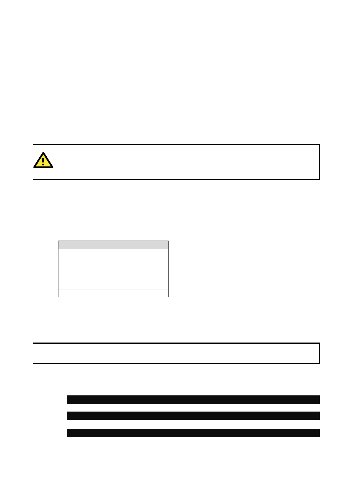
2. Use the minicom –s command to enter the configuration menu and set up the serial port settings.
Arm-based computer. Do NOT
Page 8
Arm-based Computer Linux Debian 9 UM Getting Started
2-3
user@PC1:~# minicom
NOTE
These steps apply to the Windows PC you are us
these steps to the
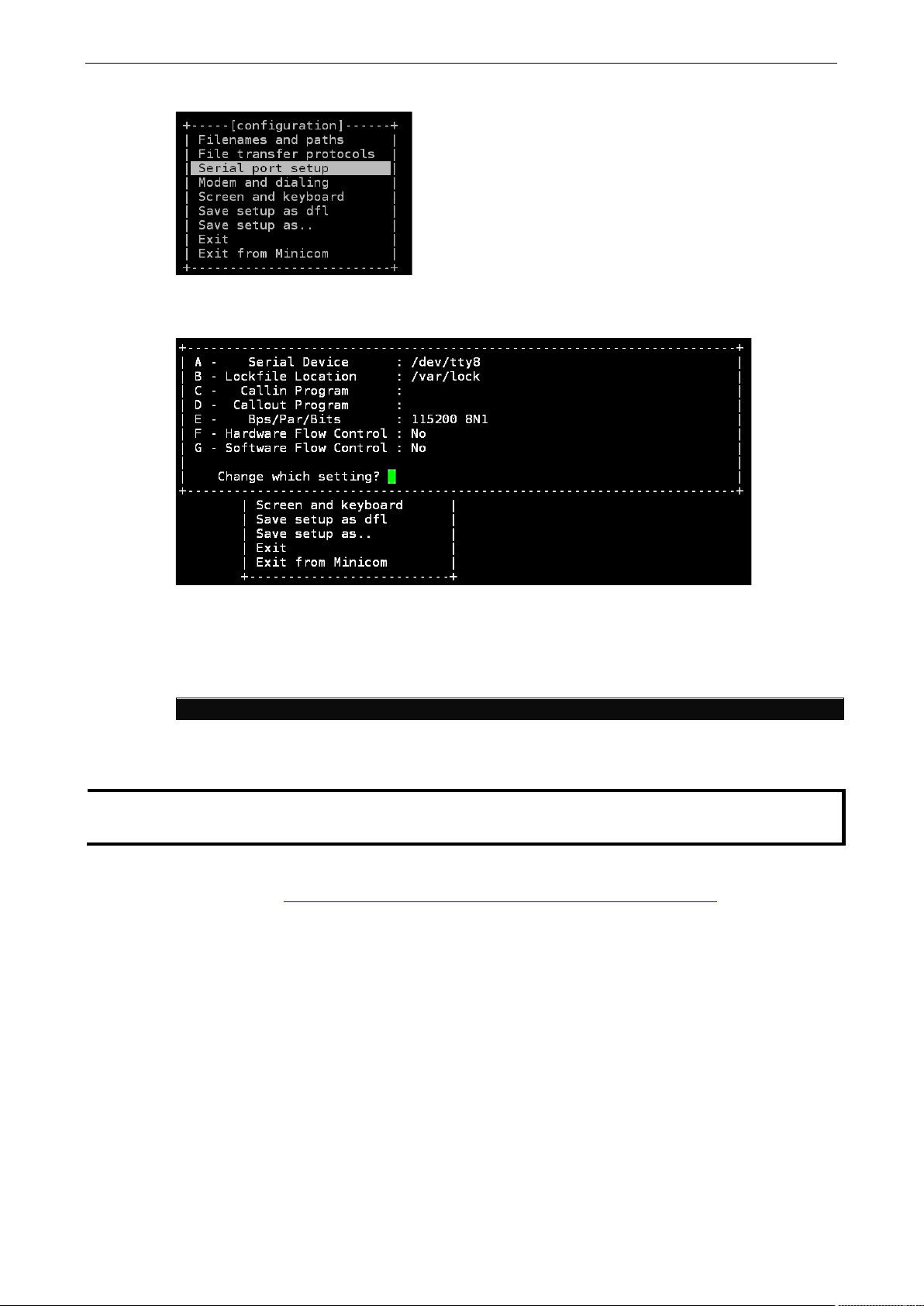
3. Select Serial port setup.
4. Select A to change the serial device. Note that you need to know which device node is connected to the
Arm-based computer.
5. Select E to configure the port settings according to the Serial Console Port Settings table provided.
6. Select Save setup as dfl (from the main configuration menu) to use default values.
7. Select Exit from minicom (from the configuration menu) to leave the configuration menu.
8. Execute minicom after completing the above configurations.
153BWindows Users
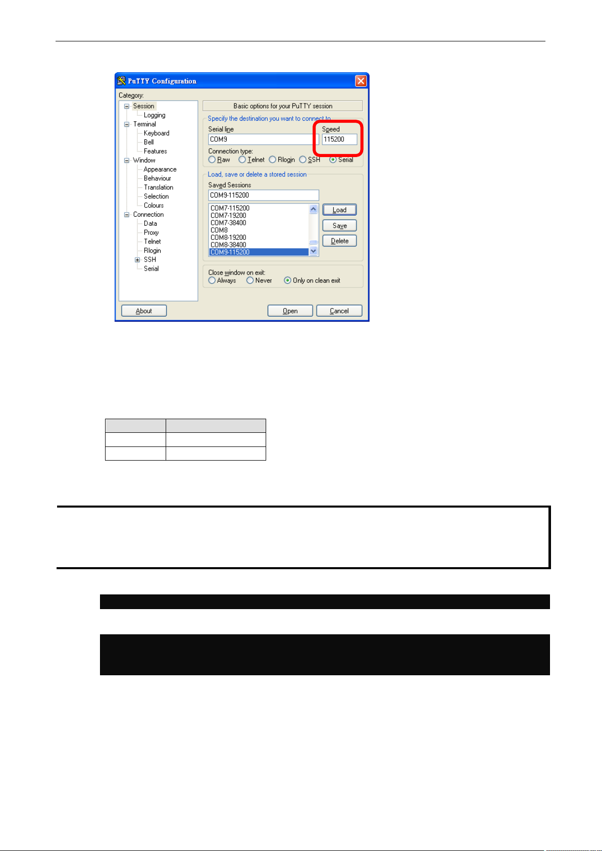
Take the following steps to connect to the Arm-based computer from your Windows PC.
1. Download PuTTY http://www.chiark.greenend.org.uk/~sgtatham/putty/download.html
connection with the Arm-based computer in a Windows environment. The figure below shows a simple
example of the configuration that is required.
ing to connect to the Arm-based computer. Do NOT apply
Arm-based computer itself.
to set up a serial
Page 9
Arm-based Computer Linux Debian 9 UM Getting Started
2-4
LAN 1
192.168.3.127
NOTE
These steps apply to the Linux PC you are using to connect to the
. Do NOT apply these
steps to the
address of your notebook/PC's Ethernet interface in the
192.168.4.0/24 for LAN2.
user@PC1:~ ssh moxa@192.168.3.127
The authenticity of host ‘192.168.3.127’ can’t be established.
Are you sure you want to continue connection (yes/no)? yes_
2. Once the connection is established, the following window will open.
3. Select the Serial connection type and choose settings that are similar to the Minicom settings.
70BConnecting via the SSH Console
The Arm-based computer supports SSH connections over an Ethernet network. Use the following default IP
addresses to connect to the Arm-based computer.
Port Default IP
LAN 2 192.168.4.127
154BLinux Users
Arm-based computer itself. Before you run the ssh command, be sure to configure the IP
Use the ssh command from a Linux computer to access the computer’s LAN1 port.
Type yes to complete the connection.
RSA key fingerprint is 8b:ee:ff:84:41:25:fc:cd:2a:f2:92:8f:cb:1f:6b:2f.
Arm-based computer
range of 192.168.3.0/24 for LAN1 and
Page 10
Arm-based Computer Linux Debian 9 UM Getting Started
2-5
ATTENTION
Rekey SSH regularly
In order to secure your system, we suggest doing a regular SSH
W
moxa@Moxa:~$ cd /etc/ssh
moxa@Moxa:~$ sudo /etc/init.d/ssh restart
For more information about SSH, refer to the following link.
https://wiki.debian.org/SSH
NOTE
These steps apply to the Windows PC you are using to connect to the
these steps to the
hen prompted for a passphrase, leave the passphrase empty and press enter.
-rekey, as shown in the following steps:
moxa@Moxa:~$ sudo rm –rf
ssh_host_ed25519_key2 ssh_host_ecdsa_key ssh_host_rsa_key
ssh_host_ed25519_key.pub ssh_host_ecdsa_key.pub ssh_host_rsa_key.pub
moxa@Moxa:~$ sudo ssh-keygen -t rsa -f /etc/ssh/ssh_host_rsa_key
moxa@Moxa:~$ sudo ssh-keygen -t dsa -f /etc/ssh/ssh_host_dsa_key
moxa@Moxa:~$ sudo ssh-keygen -t ecdsa –f /etc/ssh/ssh_host_ecdsa_key
155BWindows Users
Arm-based computer itself.
Arm-based computer. Do NOT apply
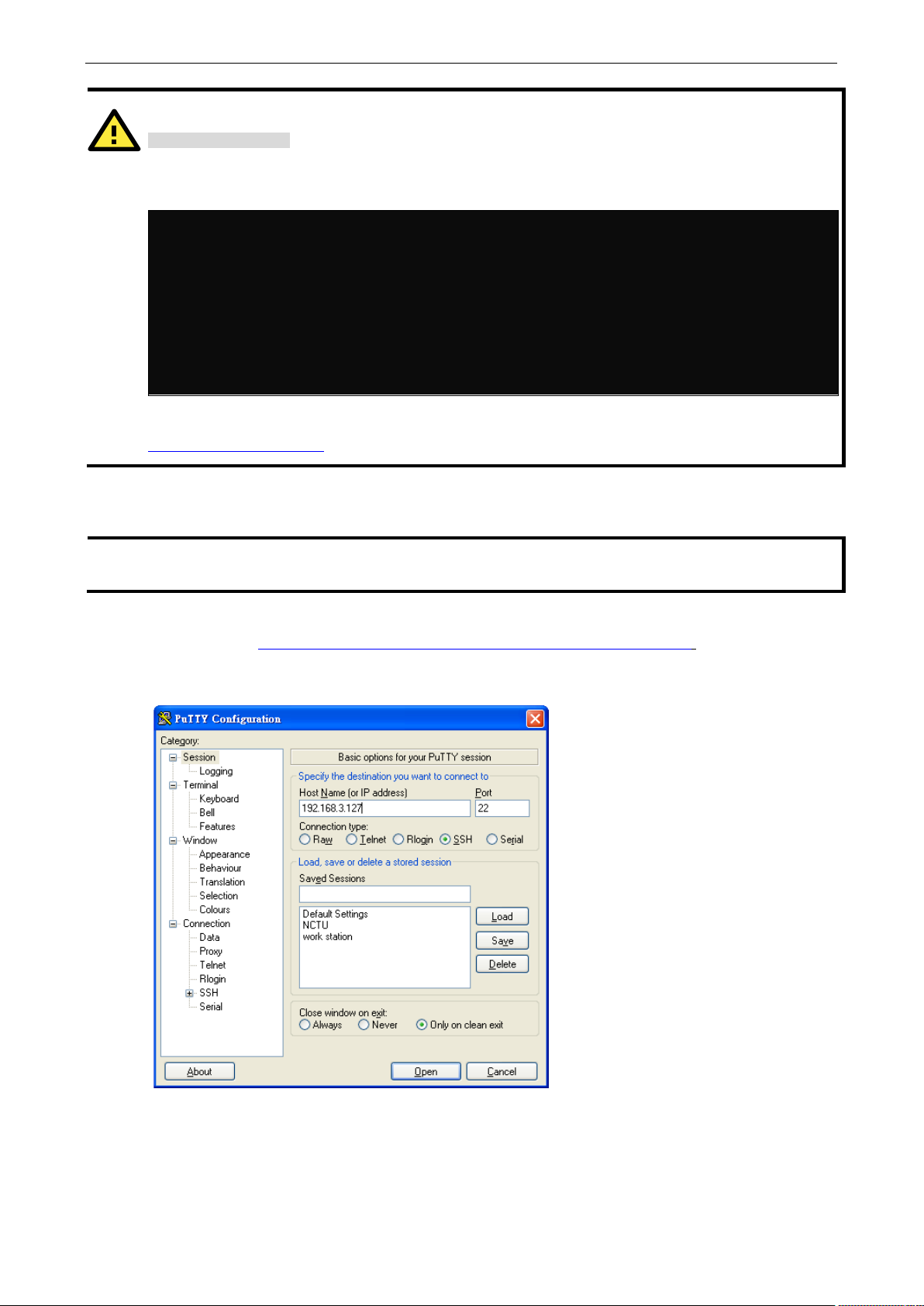
Take the following steps from your Windows PC.
Click on the link http://www.chiark.greenend.org.uk/~sgtatham/putty/download.html
(free software) to set up an SSH console for the Arm-based computer in a Windows environment. The
following figure shows a simple example of the configuration that is required.
to download PuTTY
Page 11

Arm-based Computer Linux Debian 9 UM Getting Started
2-6
NOTE
Click the following link for more information on the sudo command.
https://wiki.debian.org/sudo
ATTENTION
You m
account.
You must use
Note
moxa@Moxa:~# sudo useradd -m -G sudo -s /bin/bash test1
moxa@Moxa:~# sudo passwd test1
passwd: password updated successfully
moxa@Moxa:# sudo userdel test1
ATTENTION
You should first create a user account before you disable the default account.
root@Moxa:# passwd –l moxa
root@Moxa:# passwd –u moxa
User Account Management
71BSwitching to the Root Account
You can switch to root account using the sudo -i (or sudo su) command. For security reasons, do not
operate the
all commands from the root account.
ight get the permission denied message when using pipe or redirect behavior with a non-root
‘sudo su –c’ to run the command instead of using >, <, >>, <<, etc.
: The single quotes enclosing the full command are required.
Creating and Deleting User Accounts
You can use the useradd and userdel commands to create and delete user accounts. Be sure to
reference the main page of these commands to set relevant access privileges for the account. Following
example shows how to create a
home directory at
To change the password for test1, use the passwd option along with the new password. Retype the
password to confirm the change.
/home/test1:
Enter new UNIX password:
Retype new UNIX password:
To delete the user test1, use the userdel command.
test1 user in the sudo group whose default login shell is bash and has
Disabling the Default User Account
Use the passwd command to lock the default user account so that the moxa user cannot log in.
To unlock the user moxa:
Page 12

Arm-based Computer Linux Debian 9 UM Getting Started
2-7
moxa@Moxa:~$ cd /etc/network/
moxa@Moxa:/etc/network/~$
# interfaces(5) file used by ifup(8) and ifdown(8)
broadcast 192.168.4.255~
Network Settings
72BConfiguring Ethernet Interfaces
After the first login, you can configure the Arm-based computer’s network settings to fit your application
better. Note that it is more convenient to manipulate the network interface settings from the serial console
than from an SSH login because an SSH connection can disconnect when there are network issues and the
connection must be reestablished.
156BModifying Network Settings via the Serial Console
In this section, we use the serial console to configure the Arm-based computer’s network settings. Follow
the instructions in the Connecting to the Arm-based Computer section under Getting Started, to access the
Console Utility of the target computer via the serial Console port, and then type
change directories.
Type sudo vi interfaces to edit the network configuration file in the vi editor. You can configure the
Arm-based computer’s Ethernet ports to use either static or dynamic (DHCP) IP addresses.
cd /etc/network to
157BSetting a Static IP address
To set a static IP address for the Arm-based computer, use the iface command to modify the default
gateway, address, network, netmask, and broadcast parameters of the Ethernet interface.
auto eth0 eth1 lo
iface lo inet loopback
# embedded ethernet LAN1
#iface eth0 inet dhcp
iface eth0 inet static
address 192.168.3.127
network 192.168.3.0
netmask 255.255.255.0
broadcast 192.168.3.255
# embedded ethernet LAN2
iface eth1 inet static
address 192.168.4.127
network 192.168.4.0
netmask 255.255.255.0
Page 13

Arm-based Computer Linux Debian 9 UM Getting Started
2-8
# embedded ethernet LAN1
iface eth0 inet dhcp
moxa@Moxa:~$ kversion
UC-2112-LX version 1.1
moxa@Moxa:~$ kversion -a
UC-2112-LX version 1.1 Build 18031118
moxa@Moxa:~$ sudo date 071123192014
Mon Jul 11 23:19:00 UTC 2014
moxa@Moxa:~$ sudo hwclock –w
2018-07-31 02:09:00.628145+0000
NOTE
Click the following links for more information on
https://www.debian.org/doc/manuals/system
https://wiki.debian.org/DateTime
158BSetting Dynamic IP Addresses
To configure one or both LAN ports to request an IP address dynamically use the dhcp option in place of the
static in the iface command as follows:
Default Setting for LAN1 Dynamic Setting using DHCP
iface eth0 inet static
address 192.168.3.127
network: 192.168.3.0
netmask 255.255.255.0
broadcast 192.168.3.255
iface eth0 inet dhcp
System Administration
74BQuerying the Firmware Version
To check the Arm-based computer’s firmware version, type:
Add the –a option to create a full build version:
75BAdjusting the Time
The Arm-based computer has two time settings. One is the system time, and the other is the RTC (Real
Time Clock) time kept by the Arm-based computer’s hardware. Use the
current system time or set a new system time. Use the
or set a new RTC time.
Use the
MM = Month
DD = Date
hhmm = hour and minute
Use the following command to set the RTC time to system time:
date MMDDhhmmYYYY command to set the system time:
date command to query the
hwclock command to query the current RTC time
moxa@Moxa:~$ sudo hwclock
date and time:
-administrator/ch-sysadmin-time.html
Page 14

Arm-based Computer Linux Debian 9 UM Getting Started
2-9
moxa@Moxa:~$ TZ=EST5EDT
moxa@Moxa:~$ export TZ
+1
ECT
European Central Time
+8
CTT
China
+10
AET
Eastern Australia
-7
PNT
Arizona
76BSetting the Time Zone
There are two ways to configure the Moxa embedded computer’s time zone. One is using the TZ variable.
The other is using the /etc/localtime file.
159BUUsing the TZ Variable
The format of the TZ environment variable looks like this:
TZ=<Value>HH[:MM[:SS]][daylight[HH[:MM[:SS]]][,start date[/starttime], enddate[/endtime]]]
Here are some possible settings for the North American Eastern time zone:
1.
TZ=EST5EDT
2. TZ=EST0EDT
3. TZ=EST0
In the first case, the reference time is GMT and the stored time values are correct worldwide. A simple
change of the TZ variable can print the local time correctly in any time zone.
In the second case, the reference time is Eastern Standard Time and the only conversion performed is for
Daylight Saving Time. Therefore, there is no need to adjust the hardware clock for Daylight Saving Time
twice per year.
In the third case, the reference time is always the time reported. You can use this option if the hardware
clock on your machine automatically adjusts for Daylight Saving Time or you would like to manually adjust
the hardware time twice a year.
You must include the TZ setting in the /etc/rc.local file. The time zone setting will be activated when
you restart the computer.
The following table lists other possible values for the TZ environment variable:
Hours From Greenwich Mean Time (GMT) Value Description
0 GMT Greenwich Mean Time
+2 EET European Eastern Time
+2 ART
+3 EAT Saudi Arabia
+3.5 MET Iran
+4 NET
+5 PLT West Asia
+5.5 IST India
+6 BST Central Asia
+7 VST Bangkok
+9 JST Japan
+9.5 ACT Central Australia
+11 SST Central Pacific
+12 NST New Zealand
-11 MIT Samoa
-10 HST Hawaii
-9 AST Alaska
-8 PST Pacific Standard Time
Page 15

Arm-based Computer Linux Debian 9 UM Getting Started
2-10
-6
CST
Central Standard Time
-4
PRT
Atlantic Standard Time
moxa@Moxa:~$ df -h
tmpfs 50M 0 50M 0% /run/shm
moxa@Moxa:~$ sudo shutdown -h now
Hours From Greenwich Mean Time (GMT) Value Description
-7 MST Mountain Standard Time
-5 EST Eastern Standard Time
-5 IET Indiana East
-3.5 CNT Newfoundland
-3 AGT Eastern South America
-3 BET Eastern South America
-1 CAT Azores
160BUsing the localtime File
The local time zone is stored in the /etc/localtime and is used by GNU Library for C (glibc) if no value
has been set for the TZ environment variable. This file is either a copy of the
or a symbolic link to it. The Arm-based computer does not provide
should find a suitable time zone information file and write over the original local time file in the Arm-based
computer.
/usr/share/zoneinfo/ files. You
/usr/share/zoneinfo/ file
Determining Available Drive Space
To determine the amount of available drive space, use the df command with the –h option. The system will
return the amount of drive space broken down by file system. Here is an example:
Filesystem Size Used Avail Use% Mounted on
devtmpfs 803M 238M 524M 32% /
/dev/root 803M 238M 524M 32% /
tmpfs 25M 188K 25M 1% /run
tmpfs 5.0M 0 5.0M 0% /run/lock
tmpfs 10M 0 10M 0% /dev
Shutting Down the Device
To shut down the device, disconnect the power source to the computer. When the computer is powered off,
main components such as the CPU, RAM, and storage devices are powered off, although an internal clock
may retain battery power.
You can use the Linux command
However, main components such as the CPU, RAM, and storage devices will continue to be powered after
you run this command.
shutdown to close all software running on the device and halt the system.
Page 16

3
77BT
3. Advanced Configuration of Peripherals
In this chapter, we include more information on the Arm-based computer’s peripherals, such as the serial
interface, storage, diagnostic LEDs, and the cellular module. The instructions in this chapter cover all
functions supported in Moxa’s Arm-based computers. Before referring to the sections in this chapter, make
sure that they are applicable to and are supported by the hardware specification of your Arm-based
computer.
The following topics are covered in this chapter:
Serial Ports
Changing the Serial Terminal Settings
USB Port
USB Automount
CAN Bus Interface
Configuring the Socket CAN Interface
CAN Bus Programming Guide
Configuring the Real COM Mode
Mapping TTY Ports
Mapping TTY Ports (automatic)
Mapping TTY Ports (manual)
Removing Mapped TTY Ports
Page 17

Arm-based Computer Linux Debian 9 UM Advanced Configuration of Peripherals
3-2
2
RS-422 / RS-485 4-wire
root@Moxa:/home/moxa# mx-uart-ctl -p 0
Current uart mode is RS422/RS485-4W interface.
moxa@Moxa:~$ sudo stty -a -F /dev/ttyM0
echoctl echoke
moxa@Moxa:~$ sudo stty 115200 -F /dev/ttyM0
Serial Ports
The serial ports support RS-232, RS-422, and RS-485 2-wire operation modes with flexible baudrate
settings. The default operation mode is RS-232; use the
mode.
Usage: mx-uart-ctl -p <#port_number> -m <#uart_mode>
Port number: n = 0,1,2,...
uart mode: As in the following table
Interface-no Operation Mode
None Display current setting
0 RS-232
1 RS-485 2-wire
For example, to set Port 0 to the RS-485 4-wire mode, use the following command:
Current uart mode is RS232 interface.
root@Moxa:/home/moxa# mx-uart-ctl -p 0 -m 2
Set OK.
mx-uart-ctl command to change the operation
77BTChanging the Serial Terminal Settings
The stty command is used to view and modify the serial terminal settings. The details are given below.
161BDisplaying All Settings
Use the following command to display all serial terminal settings.
speed 9600 baud; rows 0; columns 0; line = 0;
intr = ^C; quit = ^\; erase = ^?; kill = ^U; eof = ^D; eol = <undef>;
eol2 = <undef>; swtch = <undef>; start = ^Q; stop = ^S; susp = ^Z; rprnt = ^R;
werase = ^W; lnext = ^V; flush = ^O; min = 1; time = 0;
-parenb -parodd cs8 hupcl -cstopb cread clocal -crtscts
-ignbrk -brkint -ignpar -parmrk -inpck -istrip -inlcr -igncr icrnl ixon -ixoff
-iuclc -ixany -imaxbel -iutf8
opost -olcuc -ocrnl onlcr -onocr -onlret -ofill -ofdel nl0 cr0 tab0 bs0 vt0 ff0
isig icanon iexten echo echoe echok -echonl -noflsh -xcase -tostop -echoprt
162BConfiguring Serial Settings
The following example changes the baudrate to 115200.
Page 18

Arm-based Computer Linux Debian 9 UM Advanced Configuration of Peripherals
3-3
moxa@Moxa:~$ sudo stty -a -F /dev/ttyM0
echoctl echoke
NOTE
Detailed information on the stty
http://www.gnu.org/software/coreutils/manual/coreutils.html
moxa@Moxa:~$ mount | grep media
ATTENTION
Remember to type the
of data
E
auto
manually.
Check the settings to confirm that the baudrate has changed to 115200.
speed 115200 baud; rows 0; columns 0; line = 0;
intr = ^C; quit = ^\; erase = ^?; kill = ^U; eof = ^D; eol = <undef>;
eol2 = <undef>; swtch = <undef>; start = ^Q; stop = ^S; susp = ^Z; rprnt = ^R;
werase = ^W; lnext = ^V; flush = ^O; min = 1; time = 0;
-parenb -parodd cs8 hupcl -cstopb cread clocal -crtscts
-ignbrk -brkint -ignpar -parmrk -inpck -istrip -inlcr -igncr icrnl ixon -ixoff
-iuclc -ixany -imaxbel -iutf8
opost -olcuc -ocrnl onlcr -onocr -onlret -ofill -ofdel nl0 cr0 tab0 bs0 vt0 ff0
isig icanon iexten echo echoe echok -echonl -noflsh -xcase -tostop -echoprt
USB Port
The Arm-based computers are provided with a USB port for storage expansion.
USB Automount
The Arm-based computers support hot plug function for connecting USB mass storage devices. However, by
default, the
command to view details about all partitions.
xit from the /media/* directory when you disconnect the storage device. If you stay in /media/usb*, the
unmount process will fail. If that happens, type #umount /media/usb* to unmount the device
automount utility (udev) only supports auto-mounting of one partition. Use the mount
.
utility is available at the following link:
sync command before you disconnect the USB mass storage device to prevent loss
Page 19

Arm-based Computer Linux Debian 9 UM Advanced Configuration of Peripherals
3-4
# ip link
can0: <NOARP,UP,LOWER_UP,ECHO> mtu 16 qdisc pfifo_fast state UNKNOWN mode DEFAULT
group default qlen 10 link/can
# ip link set can0 down
qlen 10 link/can
# ip link set can0 up type can bitrate 12500
#include <stdio.h>
ioctl(s, SIOCGIFINDEX, &ifr);
CAN Bus Interface
The CAN ports on Moxa’s Arm-based computers support CAN 2.0A/B standard.
Configuring the Socket CAN Interface
The CAN ports are initialized by default. If any additional configuration is needed, use the ip link
command to check the CAN device.
To check the CAN device status, use the ip link command.
To configure the CAN device, use # ip link set can0 down to turn off the device first
# ip link
can0: <NOARP,ECHO> mtu 16 qdisc pfifo_fast state DOWN mode DEFAULT group default
CAN Bus Programming Guide
CAN Write
Here’s an example with bitrate 12500:
The following code is an example of the SocketCAN API, which sends packets using the raw interface.
#include <stdlib.h>
#include <unistd.h>
#include <string.h>
#include <net/if.h>
#include <sys/types.h>
#include <sys/socket.h>
#include <sys/ioctl.h>
#include <linux/can.h>
#include <linux/can/raw.h>
int main(void)
{
int s;
int nbytes;
struct sockaddr_can addr;
struct can_frame frame;
struct ifreq ifr;
char *ifname = "can1";
if((s = socket(PF_CAN, SOCK_RAW, CAN_RAW)) < 0) {
perror("Error while opening socket");
return -1;
}
strcpy(ifr.ifr_name, ifname);
Page 20

Arm-based Computer Linux Debian 9 UM Advanced Configuration of Peripherals
3-5
addr.can_family = AF_CAN;
}
#include <stdio.h>
perror("Error in can raw socket read");
addr.can_ifindex = ifr.ifr_ifindex;
printf("%s at index %d\n", ifname, ifr.ifr_ifindex);
if(bind(s, (struct sockaddr *)&addr, sizeof(addr)) < 0) {
perror("Error in socket bind");
return -2;
}
frame.can_id = 0x123;
frame.can_dlc = 2;
frame.data[0] = 0x11;
frame.data[1] = 0x22;
nbytes = write(s, &frame, sizeof(struct can_frame));
printf("Wrote %d bytes\n", nbytes);
return 0;
CAN Read
The following sample code illustrates how to read the data.
#include <stdlib.h>
#include <unistd.h>
#include <string.h>
#include <net/if.h>
#include <sys/types.h>
#include <sys/socket.h>
#include <sys/ioctl.h>
#include <linux/can.h>
#include <linux/can/raw.h>
Int main(void)
{
int i;
int s;
int nbytes;
struct sockaddr_can addr;
struct can_frame frame;
struct ifreq ifr;
char *ifname = "can0";
if((s = socket(PF_CAN, SOCK_RAW, CAN_RAW)) < 0) {
perror("Error while opening socket");
return -1;
}
strcpy(ifr.ifr_name, ifname);
ioctl(s, SIOCGIFINDEX, &ifr);
addr.can_family = AF_CAN;
addr.can_ifindex = ifr.ifr_ifindex;
printf("%s at index %d\n", ifname, ifr.ifr_ifindex);
if(bind(s, (struct sockaddr *)&addr, sizeof(addr)) < 0) {
perror("Error in socket bind");
return -2;
}
nbytes = read(s, &frame, sizeof(struct can_frame));
if (nbytes < 0) {
Page 21

Arm-based Computer Linux Debian 9 UM Advanced Configuration of Peripherals
3-6
return 1;
}
IMPORTANT!
The
}
if (nbytes < sizeof(struct can_frame)) {
fprintf(stderr, "read: incomplete CAN frame\n");
return 1;
}
printf(" %5s %03x [%d] ", ifname, frame.can_id, frame.can_dlc);
for (i = 0; i < frame.can_dlc; i++)
printf(" %02x", frame.data[i]);
printf("\n");
return 0;
After you use the SocketCAN API, the SocketCAN information is written to the paths:
/proc/sys/net/ipv4/conf/can* and /proc/sys/net/ipv4/neigh/can*
Configuring the Real COM Mode
UC-8100, UC-8100-ME-T, and UC-8100A-ME-T Series do not support Real COM mode.
You can use Moxa’s NPort series serial device drivers to extend the number of serial interfaces (ports) on
your Arm-based Moxa computer. The NPort comes equipped with COM drivers that work with Windows
systems and TTY drivers for Linux systems. The driver establishes a transparent connection between the
host and serial device by mapping the IP Port of the NPort’s serial port to a local COM/TTY port on the host
computer.
Real COM Mode also supports up to 4 simultaneous connections, so that multiple hosts can collect data from
the same serial device at the same time.
One of the major conveniences of using Real COM Mode is that Real COM Mode allows users to continue
using RS-232/422/485 serial communications software that was written for pure serial communications
applications. The driver intercepts data sent to the host’s COM port, packs it into a TCP/IP packet, and then
redirects it through the host’s Ethernet card. At the other end of the connection, the NPort accepts the
Ethernet frame, unpacks the TCP/IP packet, and then sends it transparently to the appropriate serial device
attached to one of the NPort’s serial ports.
The Real COM driver is installed on the Arm-based computer by default. You will be able to view the driver
related files in the /usr/lib/npreal2/driver folder.
> mxaddsvr (Add Server, mapping tty port) > mxdelsvr (Delete Server,
unmapping tty port)
> mxloadsvr (Reload Server) > mxmknod (Create device node/tty port)
> mxrmnod (Remove device node/tty port)
> mxuninst (Remove tty port and driver files)
At this point, you will be ready to map the NPort serial port to the system tty port. For a list of supported
NPort devices and their revision history, click https://www.moxa.com/en/support/search?psid=50278
.
Page 22

Arm-based Computer Linux Debian 9 UM Advanced Configuration of Peripherals
3-7
# cd /usr/lib/npreal2/driver
# ./mxaddsvr 192.168.3.4 16
# cd /usr/lib/npreal2/driver
# ./mxaddsvr 192.168.3.4 16 4001 966
# cd /usr/lib/npreal2/driver
# ./mxdelsvr 192.168.3.4
Mapping TTY Ports
Make sure that you set the operation mode of the desired NPort serial port to Real COM mode. After logging
in as a super user, enter the directory /usr/lib/npreal2/driver and then execute mxaddsvr to map the target
NPort serial port to the host tty ports. The syntax of
mxaddsvr command is as follows:
mxaddsvr [NPort IP Address] [Total Ports] ([Data port] [Cmd port])
The mxaddsvr command performs the following actions:
1. Modifies the npreal2d.cf.
2. Creates tty ports in the /dev directory with major & minor number configured in npreal2d.cf.
3. Restarts the driver.
Mapping TTY Ports (automatic)
To map tty ports automatically, execute the mxaddsvr command with just the IP address and the number
of ports, as shown in the following example:
In this example, 16 tty ports will be added, all with IP 192.168.3.4 consisting of data ports from 950 to 965
and command ports from 966 to 981.
Mapping TTY Ports (manual)
To map tty ports manually, execute the mxaddsvr command and specify the data and command ports as
shown in the following example:
In this example, 16 tty ports will be added, all with IP 192.168.3.4, with data ports from 4001 to 4016 and
command ports from 966 to 981.
Removing Mapped TTY Ports
After logging in as root, enter the directory /usr/lib/npreal2/driver and then execute the mxdelsvr
command to delete a server. The syntax of
mxdelsvr [IP Address]
Example:
mxdelsvr is:
The following actions are performed when the mxdelsvr command is executed:
1. Modify npreal2d.cf.
2. Remove the relevant tty ports from the /dev directory.
3. Restart the driver.
If the IP address is not provided in the command line, the program will list the installed servers and total
ports on the screen. You will need to choose a server from the list for deletion.
Page 23

4
4. Configuring of Wireless Connectivity
The instructions in this chapter cover all wireless functions supported in Moxa’s Arm-based computers.
Before referring to the sections in this chapter, make sure that they are applicable to and are supported by
the hardware specification of your Arm-based computer platform.
The following topics are covered in this chapter:
Configuring the Cellular Connection
Using Cell_mgmt
Dial-up Process
Dial-up Commands
Cellular Module
Configuring a NB-IoT/Cat. M1 Connection (UC-2114 and UC-2116 only)
GPS
Configuring the Wi-Fi Connection
Configuring WPA2
Configuring the Bluetooth Connection
Paring Devices
Connecting Devices
Page 24

4-2
NAME
Power cycle the module slot.
Arm-based Computer Linux Debian 9 UM Configuring of Wireless Connectivity
Configuring the Cellular Connection
Using Cell_mgmt
The cell_mgmt utility is used to manage the cellular module in the computer. To run the cell_mgmt
command, you must use
and MMS communication.
Manual Page
cell_mgmt
USAGE
cell_mgmt [-i <module id>] [options]
OPTIONS
-i <module id>
Module identifier, start from 0 and default to 0.
-s <slot id>
Slot identifier, start from 1 and default value depends
on module interface.
example: module 0 may in slot 2
modules
Shows module numbers supported.
slot
Shows module slot id
interface [interface id]
Switching and checking module interface(s)
start [OPTIONS]
Start network.
OPTIONS:
PIN - PIN code
Phone - Phone number (especially for AT based modules)
Auth - Authentication type(CHAP|PAP|BOTH), default=NONE.
Username
Password
example:
cell_mgmt start
cell_mgmt start PIN=0000
cell_mgmt start PIN=0000 Phone=*99#
cell_mgmt start PIN=0000 Phone=*99# \
Auth=BOTH Username=moxa Password=moxamoxa
stop
network.
power_on
Power ON.
power_off
Power OFF.
power_cycle
sudo or run the command with root permission. The utility does not support SMS
Page 25

Arm-based Computer Linux Debian 9 UM Configuring of Wireless Connectivity
4-3
switch_sim <1|2>
Cellular management version.
Switch SIM slot.
gps_on
GPS ON.
gps_off
GPS OFF.
attach_status
Query network registration status.
status
Query network connection status.
signal
Get signal strength.
at <'AT_COMMAND'>
Input AT Command.
Must use SINGLE QUOTATION to enclose AT Command.
sim_status
Query sim card status.
unlock_pin <PIN>
Unlock PIN code and save to configuration file.
pin_retries
Get PIN code retry remain times.
pin_protection <enable|disable> <current PIN>
Set PIN protection in the UIM.
set_flight_mode <0|1>
Set module into flight mode (1) or online mode (0).
set_apn <APN>
Set APN to configuration file.
check_carrier
Check current carrier.
switch_carrier <Verizon|ATT|Sprint|Generic>
Switching between US carrier frequency bands.
m_info
Module/SIM information.
module_info
Module information.
module_ids
Get device IDs (ex: IMEI and/or ESN).
iccid
Get SIM card ID
imsi
Get IMSI (International Mobile Subscriber Identity).
location_info
Get cell location information.
operator
Telecommunication operator.
vzwauto
Verizon Private Network auto dialup.
version
Page 26

Arm-based Computer Linux Debian 9 UM Configuring of Wireless Connectivity
4-4
moxa@Moxa:/home/moxa$ sudo cell_mgmt sim_status
+CPIN: READY
moxa@Moxa:/home/moxa$ sudo cell_mgmt set_apn internet
old APN=test, new APN=internet
moxa@Moxa:/home/moxa$ sudo cell_mgmt attach_status
PS: attached
moxa@Moxa:/home/moxa$ sudo cell_mgmt start
Network started successfully
moxa@Moxa:/home/moxa$ sudo cell_mgmt stop
Clearing state...
Dial-up Process
Before dialing, ensure that the APN (Access Point Name) is set correctly and the cellular module has attach
with the base station.
1. Unlock the PIN code (if the SIM is locked using a PIN code).
Use the
unlock_pin
2. Use the cell_mgmt set_apn <APN> command to set the name of the access point that will be used
to connect to the carrier.
3. Check if the service attaches with the correct APN.
PS (packet-switched) should be attached to establish a network connection.
cell_mgmt sim_status command to check the SIM card status and the cell_mgmt
<PIN> command to unlock the SIM card if a SIM PIN is set.
CS: attached
4. Dial up using the
cell_mgmt start command.
PIN code: Disabled or verified
Starting network with '_qmicli --wds-start-network=apn=internet,ip-type=4 --
client-no-release-cid --device-open-net=net-802-3|net-no-qos-header'...
Saving state... (CID: 8)
Saving state... (PDH: 1205935456)
The dial-up function in the cell_mgmt utility will automatically set the DNS and default gateway of the
computer, if they have not been set.
Dial-up Commands
cell_mgmt start
To start a network connection, use the default cellular module of the computer (If the computer supports
multiple modules, use the
If you run the
will be written into the configuration file
This information is then used when you run the command without specifying the options.
cell_mgmt start command with the Username, Password, and PIN, all the configurations
cell_mgmt interface command to verify the default module that is selected).
/etc/moxa-cellular-utils/moxa-cellular-utils.conf.
Usage:
cell_mgmt start Username=[user] Password=[pass] PIN=[pin_code]
cell_mgmt stop
Stops/disables the network connection on the cellular module of the computer
Killed old client process
Stopping network with '_qmicli --wds-stop-network=1205933264 --client-cid=8'...
Network stopped successfully
Page 27

Arm-based Computer Linux Debian 9 UM Configuring of Wireless Connectivity
4-5
moxa@Moxa:/home/moxa$ sudo cell_mgmt status
Status: connected
root@Moxa:/home/moxa$ sudo cell_mgmt signal
4G Level 4 (Good)
Level
Description
3
Fair
moxa@Moxa:/home/moxa$ sudo cell_mgmt signal
umts -77 dbm
-105 to -115 dBm
Poor
moxa@Moxa:/home/moxa$ sudo cell_mgmt operator
Chunghwa
cell_mgmt status
Provides information on the status of the network connection.
cell_mgmt signal
Provides the cellular signal strength.
For moxa-cellular-utils version 2.0.0 and later, cellular signal strength is indicated using levels.
5 Excellent
4 Good
2 Poor
1 Very Poor
0 No Signal
For moxa-cellular-utils versions prior to version 2.0.0, the cellular signal strength is measured using
Reference Signal Received Power (RSRP). The following table lists the signal strength for RSRP ranges.
RSRP Signal Strength
<-115 dBm No signal
-95 to -105 dBm Fair
-85 to -95 dBm Good
>-85 dBm Excellent
cell_mgmt operator
Provides information on the cellular service provider.
Page 28

Arm-based Computer Linux Debian 9 UM Configuring of Wireless Connectivity
4-6
moxa@Moxa:/home/moxa$ sudo cell_mgmt module_info
Modem_port: NotSupport
moxa@Moxa:/home/moxa$ sudo cell_mgmt interface
[0] wwan0 <Current>
moxa@Moxa:/home/moxa$ sudo cell_mgmt power_cycle
[232747.099156] usb 1-1: Qualcomm USB modem converter now attached to ttyUSB1
Cellular Module
cell_mgmt module_info
Provides information of the cellular module (AT port, GPS port, QMI port, and module name, etc.).
SLOT: 1
Module: MC7354
WWAN_node: wwan0
AT_port: /dev/ttyUSB2
GPS_port: /dev/ttyUSB1
QMI_port: /dev/cdc-wdm0
cell_mgmt interface [id]
Used to view the supported modules and default module on the computer with their IDs. Change the default
module by specifying the ID.
cell_mgmt power_cycle
Use the cell_mgmt power_cycle command to power cycle the cellular module in the computer. You may
see a kernel message that the module has been reloaded.
Network already stopped
Clearing state...
[232733.202208] usb 1-1: USB disconnect, device number 2
[232733.217132] qcserial ttyUSB0: Qualcomm USB modem converter now disconnected
from ttyUSB0
[232733.225616] qcserial 1-1:1.0: device disconnected
[232733.256738] qcserial ttyUSB1: Qualcomm USB modem converter now disconnected
from ttyUSB1
[232733.265214] qcserial 1-1:1.2: device disconnected
[232733.281566] qcserial ttyUSB2: Qualcomm USB modem converter now disconnected
from ttyUSB2
[232733.290006] qcserial 1-1:1.3: device disconnected
[232733.313572] qmi_wwan 1-1:1.8 wwan0: unregister 'qmi_wwan' usb-musb-
hdrc.0.auto-1, WWAN/QMI device
[232746.879873] usb 1-1: new high-speed USB device number 3 using musb-hdrc
[232747.020358] usb 1-1: config 1 has an invalid interface number: 8 but max is 3
[232747.027639] usb 1-1: config 1 has no interface number 1
[232747.036212] usb 1-1: New USB device found, idVendor=1199, idProduct=68c0
[232747.043185] usb 1-1: New USB device strings: Mfr=1, Product=2, SerialNumber=3
[232747.050473] usb 1-1: Product: MC7354
[232747.054151] usb 1-1: Manufacturer: Sierra Wireless, Incorporated
[232747.068022] qcserial 1-1:1.0: Qualcomm USB modem converter detected
[232747.079525] usb 1-1: Qualcomm USB modem converter now attached to ttyUSB0
[232747.089754] qcserial 1-1:1.2: Qualcomm USB modem converter detected
Page 29

Arm-based Computer Linux Debian 9 UM Configuring of Wireless Connectivity
4-7
[232747.109317] qcserial 1-1:1.3: Qualcomm USB modem converter detected
hdrc.0.auto-1, WWAN/QMI device, 0a:ba:e1:d6:ed:4a
moxa@Moxa:/home/moxa$ sudo cell_mgmt check_carrier
--------------------------------
[232747.118581] usb 1-1: Qualcomm USB modem converter now attached to ttyUSB2
[232747.130890] qmi_wwan 1-1:1.8: cdc-wdm0: USB WDM device
[232747.137174] qmi_wwan 1-1:1.8 wwan0: register 'qmi_wwan' at usb-musb-
cell_mgmt check_carrier
The cell_mgmt check_carrier command helps to check if the current carrier matches with the service
(SIM card) provider.
----------Carrier Info----------
preferred firmware=05.05.58.01
preferred carrier name=ATT
preferred carrier config=ATT_005.026_000
firmware=05.05.58.01
carrier name=ATT
carrier config=ATT_005.026_000
cell_mgmt switch_carrier
Some modules provide multiple carrier support. Use the cell_mgmt switch_carrier command to
switch between carriers. It may take some time (depending on the module's mechanism) to switch between
carriers.
For the UC-2114 and UC-2116 computers, refer to the following table for a list of the cellular carriers
supported.
MNO Profile
(UC-2114 & UC-2116)
Default M1/NB1 2, 3, 4, 5, 8, 12, 13, 18,
AT&T M1 only 2, 4, 5, and 12 No
China Telecom M1/NB1 3, 5, and 8 Yes
Deutsche Telekom M1/NB1 3, 8, and 20 Yes
Sprint M1 only 2, 4, 12, and 25 Yes
Standard Europe M1/NB1 3, 8, and 20 Yes
Telstra M1 only 3, 5, 8, and 28 No
T-Mobile USA NB1 only 2, 4, 5, and 12 Yes
TELUS M1 only 2, 4, 5, and 12 No
Verizon M1 only 13 No
Vodafone NB1/M1 3, 8, and 20 Yes
System Selection
(Primary/Secondary)
LTE Bands Supported UBANDMASK Support
19, 20, and 25 (M1 only)
No
Page 30

Arm-based Computer Linux Debian 9 UM Configuring of Wireless Connectivity
4-8
moxa@Moxa:/home/moxa$ sudo cell_mgmt switch_carrier
[236411.459687] qmi_wwan 1-1:1.8 wwan0: unregister 'qmi_wwan' usb-musb-
----------------------
Usage:
switch_carrier <Verizon|ATT|Sprint|Generic>
moxa@Moxa:/home/moxa$ sudo cell_mgmt switch_carrier Verizon
----------switch_carrier------------
cmd=AT!GOBIIMPREF="05.05.58.01","VZW","VZW_005.029_001"
OK
OK
wait for power cycle...
Network already stopped
Clearing state...
[236362.468977] usb 1-1: USB disconnect, device number 3
[236362.482562] qcserial ttyUSB0: Qualcomm USB modem converter now disconnected
from ttyUSB0
[236362.491019] qcserial 1-1:1.0: device disconnected
[236362.521065] qcserial ttyUSB1: Qualcomm USB modem converter now disconnected
from ttyUSB1
[236362.529430] qcserial 1-1:1.2: device disconnected
[236362.544653] qcserial ttyUSB2: Qualcomm USB modem converter now disconnected
from ttyUSB2
[236362.553133] qcserial 1-1:1.3: device disconnected
[236362.558283] qmi_wwan 1-1:1.8 wwan0: unregister 'qmi_wwan' usb-musb-
hdrc.0.auto-1, WWAN/QMI device
[236376.209868] usb 1-1: new high-speed USB device number 4 using musb-hdrc
[236376.350358] usb 1-1: config 1 has an invalid interface number: 8 but max is 3
[236376.357639] usb 1-1: config 1 has no interface number 1
[236376.364991] usb 1-1: New USB device found, idVendor=1199, idProduct=68c0
[236376.371925] usb 1-1: New USB device strings: Mfr=1, Product=2, SerialNumber=3
[236376.379217] usb 1-1: Product: MC7354
[236376.382924] usb 1-1: Manufacturer: Sierra Wireless, Incorporated
[236376.400588] qcserial 1-1:1.0: Qualcomm USB modem converter detected
[236376.412010] usb 1-1: Qualcomm USB modem converter now attached to ttyUSB0
[236376.422273] qcserial 1-1:1.2: Qualcomm USB modem converter detected
[236376.429958] usb 1-1: Qualcomm USB modem converter now attached to ttyUSB1
[236376.441031] qcserial 1-1:1.3: Qualcomm USB modem converter detected
[236376.448337] usb 1-1: Qualcomm USB modem converter now attached to ttyUSB2
[236376.461514] qmi_wwan 1-1:1.8: cdc-wdm0: USB WDM device
[236376.467762] qmi_wwan 1-1:1.8 wwan0: register 'qmi_wwan' at usb-musb-
hdrc.0.auto-1, WWAN/QMI device, 0a:ba:e1:d6:ed:4a
[236411.387228] usb 1-1: USB disconnect, device number 4
[236411.393963] qcserial ttyUSB0: Qualcomm USB modem converter now disconnected
from ttyUSB0
[236411.402361] qcserial 1-1:1.0: device disconnected
[236411.422719] qcserial ttyUSB1: Qualcomm USB modem converter now disconnected
[236411.431186] qcserial 1-1:1.2: device disconnected
[236411.446102] qcserial ttyUSB2: Qualcomm USB modem converter now disconnected
from ttyUSB2
[236411.454583] qcserial 1-1:1.3: device disconnected
Page 31

Arm-based Computer Linux Debian 9 UM Configuring of Wireless Connectivity
4-9
hdrc.0.auto-1, WWAN/QMI device
--------------------------------
moxa@Moxa:/home/moxa$ sudo cell_mgmt at 'AT+CSQ'
OK
moxa@Moxa:/home/moxa$ cell_mgmt at 'AT+COPS=2'
moxa@Moxa:/home/moxa$ cell_mgmt at 'AT+COPS=0'
moxa@Moxa:/home/moxa$ cell_mgmt at 'AT+COPS=2'
moxa@Moxa:/home/moxa$ cell_mgmt at 'AT+COPS=0'
[236423.109879] usb 1-1: new high-speed USB device number 5 using musb-hdrc
[236423.250364] usb 1-1: config 1 has an invalid interface number: 8 but max is 3
[236423.257649] usb 1-1: config 1 has no interface number 1
[236423.266064] usb 1-1: New USB device found, idVendor=1199, idProduct=68c0
[236423.273024] usb 1-1: New USB device strings: Mfr=1, Product=2, SerialNumber=3
[236423.280331] usb 1-1: Product: MC7354
[236423.284011] usb 1-1: Manufacturer: Sierra Wireless, Incorporated
[236423.298320] qcserial 1-1:1.0: Qualcomm USB modem converter detected
[236423.310356] usb 1-1: Qualcomm USB modem converter now attached to ttyUSB0
[236423.318614] qcserial 1-1:1.2: Qualcomm USB modem converter detected
[236423.328841] usb 1-1: Qualcomm USB modem converter now attached to ttyUSB1
[236423.338942] qcserial 1-1:1.3: Qualcomm USB modem converter detected
[236423.348418] usb 1-1: Qualcomm USB modem converter now attached to ttyUSB2
[236423.360733] qmi_wwan 1-1:1.8: cdc-wdm0: USB WDM device
[236423.366960] qmi_wwan 1-1:1.8 wwan0: register 'qmi_wwan' at usb-musb-
hdrc.0.auto-1, WWAN/QMI device, 0a:ba:e1:d6:ed:4a
moxa@Moxa:/home/moxa$ sudo cell_mgmt check_carrier
----------Carrier Info----------
preferred firmware=05.05.58.01
preferred carrier name=VZW
preferred carrier config=VZW_005.029_001
firmware=05.05.58.01
carrier name=VZW
carrier config=VZW_005.029_001
cell_mgmt at AT_COMMAND
Used to input an AT command. For example, use the AT command, AT+CSQ as follows:
+CSQ: 18,99
Configuring a NB-IoT/Cat. M1 Connection (UC-2114 and UC-
2116 only)
You can change the RAT (radio access technology) type of the NB-IoT module in UC-2114 and UC-2116
using the following AT commands:
Switching to the Cat. M1 Mode
moxa@Moxa:/home/moxa$ cell_mgmt at 'AT+URAT=7'
Switching to the NB-IoT Mode
moxa@Moxa:/home/moxa$ cell_mgmt at 'AT+URAT=8'
Page 32

Arm-based Computer Linux Debian 9 UM Configuring of Wireless Connectivity
4-10
NOTE
•
•
cell_mgmt at AT+URAT?
8: NB-IOT
root@Moxa:/home/moxa# cell_mgmt gps_on
root@Moxa:/home/moxa# cell_mgmt module_info
AT_port (reserved): NotSupport
root@Moxa:/home/moxa# cat /dev/ttyUSB1
• The APN name 'internet.iot' is set by the user. For information on the APN settings, contact your mobile
network operator.
A PPP dial-up connection that uses Cat. M1 and CAT. NB1 may sometimes take a couple of minutes to
establish a connection if the signal is weak.
Power saving mode (PSM) is not supported in the UC-2114 and UC-2116 computers.
You can also use an AT command to read the mode:
root@Moxa:/home/moxa# cell_mgmt at AT+URAT?
+URAT: 7,8
OK
7: CAT-M1
GPS
UC-8112-ME-T-US-LTE Model
To view the GPS information for the UC-8112-ME-T-US-LTE model, do the following:
1. Power on the GPS module using the command:
2. Check the GPS port using the cell_mgmt command.
In the following example, the GPS port is at /dev/ttyUSB1.
SLOT: 1
Module: MC7354
WWAN_node: wwan1
AT_port: /dev/ttyUSB2
GPS_port: /dev/ttyUSB1
QMI_port: /dev/cdc-wdm1
Modem_port: NotSupport
3. Type the following command to get the GPS location information from the GPS port.
Page 33

Arm-based Computer Linux Debian 9 UM Configuring of Wireless Connectivity
4-11
moxa@Moxa:/home/moxa$ sudo cell_mgmt module_info
Modem_port: NotSupport
root@Moxa:/home/moxa# cat /dev/ttyUSB1
ESS
Open
None
No
No
No
ESS
WPA-PSK
WEP
Yes
Yes
No
moxa@Moxa:~$ sudo wifi_mgmt help
start Type=[type] SSID=[ssid] Password=[password]
For Other Models
Use cell_mgmt module_info to get information of the cellular module including the GPS port information.
SLOT: 1
Module: MC7354
WWAN_node: wwan0
AT_port: /dev/ttyUSB2
GPS_port: /dev/ttyUSB1
QMI_port: /dev/cdc-wdm0
Type the following command to get the GPS location information from the GPS port.
Configuring the Wi-Fi Connection
You can configure the Wi-Fi connection for your Arm-based computer using a configuration file or the
wifi_mgmt utility provided by Moxa. For advanced settings, you can use the
wpa_supplicant command.
Configuring WPA2
Moxa’s Arm-based computers support WPA2 security using the /sbin/wpa_supplicant program. Refer to
the following table for the configuration options. The Key required before joining network? column
specifies whether an encryption and/or authentication key must be configured before associating with a
network.
Infrastructure
mode
ESS Open WEP Optional Optional Yes
ESS Shared None Yes No Yes
ESS Shared WEP Optional Optional Yes
ESS WPA WEP No Yes No
ESS WPA TKIP No Yes No
ESS WPA2 AES No Yes No
ESS WPA-PSK TKIP Yes Yes No
ESS WPA2-PSK AES Yes Yes No
Using wifi_mgmt
Authentication
mode
Encryption
status
Manual Key
required?
IEEE 802.1X
enabled?
Key required
before joining
network?
Manual Page
The wifi_mgmt utility manages the behavior of the Wi-Fi module.
[sudo] password for moxa:
Usage:
/usr/sbin/wifi_mgmt [-i <interface id>] [-s <slot id>] [OPTIONS]
OPTIONS
Page 34

Arm-based Computer Linux Debian 9 UM Configuring of Wireless Connectivity
4-12
Insert an AP information to the managed AP list and then connect to the AP.
Wifi management version.
[type] open/wep/wpa/wpa2
[ssid] access point's SSID
[password] access point's password
example:
wifi_mgmt start Type=wpa SSID=moxa_ap Password=moxa
wifi_mgmt start Type=open SSID=moxa_ap
start [num]
Connect to AP by the managed AP list number.
start
Connect to the last time AP that was used.
scan -d
Scan all the access points information and show the detail message.
scan
Scan all the access points information.
signal
Show the AP's signal.
list
Show the managed AP list.
insert Type=[type] SSID=[ssid] Password=[password]
Insert a new AP information to the managed AP list.
[type] open/wep/wpa/wpa2
[ssid] access point's SSID
[password] access point's password
example:
wifi_mgmt insert Type=wpa SSID=moxa_ap Password=moxa
select [num]
Select an AP num to connect which is in the managed AP list.
stop
Stop network.
status
Query network connection status.
interface [num]
Switch to another wlan[num] interface.
[num] interface number
example:
wifi_mgmt interface 0
interface
Get the current setting interface.
reconnect
Reconnect to the access point.
restart
Stop wpa_supplicant then start it again.
version
Page 35

Arm-based Computer Linux Debian 9 UM Configuring of Wireless Connectivity
4-13
root@Moxa:~# wifi_mgmt start Type=wpa SSID=moxa_ap Password=moxa
*** Get DHCP IP from AP! ***
root@Moxa:~# wifi_mgmt list
2 MOXA_AP3 any [DISABLED]
root@Moxa:~# wifi_mgmt start 1
*** Get DHCP IP from AP! ***
root@Moxa:~# wifi_mgmt list
2 MOXA_AP3 any [DISABLED]
root@Moxa:~# wifi_mgmt start
*** Get DHCP IP from AP! ***
root@Moxa:~# wifi_mgmt stop
Stopped.
Connecting to an AP
You can connect your computer to an AP using the following three commands. The DNS and default gateway
will be configured automatically. If you want to use the wireless interface’s gateway, you must clean up
your computer’s default gateway configuration.
wifi_mgmt start Type=[type] SSID=[ssid] Password=[password]
Insert the AP information in the managed AP list and then connect to the AP.
wpa_state=COMPLETED
*** Get DHCP IP address from AP ***
wifi_mgmt start [num]
Connect to the AP using the managed AP list number. If you have inserted the AP information before, the
information may still be in the managed AP list. Check the managed AP list using the
command.
network id / ssid / bssid / flags
0 MOXA_AP1 any [LAST USED]
1 MOXA_AP2 any [DISABLED]
wifi_mgmt list
Choose an AP number to start.
wpa_state=COMPLETED
*** Get DHCP IP address from AP ***
wifi_mgmt start
Connect to the previous AP that was used.
network id / ssid / bssid / flags
0 MOXA_AP1 any [LAST USED]
1 MOXA_AP2 any [DISABLED]
Use the wifi_mgmt command to connect to the AP “MOXA_AP1” that was used the previous time as
follows:
wpa_state=COMPLETED
*** Get DHCP IP address from AP ***
Stop or Restart a Network Connection
wifi_mgmt stop
Page 36

Arm-based Computer Linux Debian 9 UM Configuring of Wireless Connectivity
4-14
root@Moxa:~# wifi_mgmt restart
*** Get DHCP IP from AP! ***
root@Moxa:~# wifi_mgmt insert Type=wpa2 SSID=MOXA_AP3 Password=moxa
2 MOXA_AP3 any [DISABLED]
root@Moxa:~# wifi_mgmt list
*** Get DHCP IP from AP! ***
root@Moxa:~# wifi_mgmt scan
fc:f5:28:cb:5d:93 2462 -97 [WPA2-EAP-CCMP-preauth][ESS] MHQ-NB
wifi_mgmt restart
wpa_supplicant is closed!!
wpa_state=COMPLETED
*** Get DHCP IP address from AP ***
Inserting an AP or Choosing Another AP to Connect To
If you want to insert and AP use the wifi_mgmt insert command.
root@Moxa:~# wifi_mgmt list
network id / ssid / bssid / flags
0 MOXA_AP1 any [CURRENT]
1 MOXA_AP2 any [DISABLED]
If you want to use another AP to connect, use the wifi_mgmt select command to switch to the AP.
network id / ssid / bssid / flags
0 MOXA_AP1 any [DISABLED]
1 MOXA_AP2 any [CURRENT]
2 MOXA_AP3 any [DISABLED]
root@Moxa:~# wifi_mgmt select 2
wpa_state=COMPLETED
*** Get DHCP IP address from AP ***
Other Functions
wifi_mgmt scan
Scan all of the access point information.
bssid / frequency / signal level / flags / ssid
b0:b2:dc:dd:c9:e4 2462 -57 [WPA-PSK-TKIP][ESS] WES_AP
fc:f5:28:cb:8c:23 2412 -57 [WPA2-EAP-CCMP-preauth][ESS] MHQ-NB
fe:f0:28:cb:8c:23 2412 -59 [WPA2-EAP-CCMP-preauth][ESS] MHQ-Mobile
fc:f5:28:cb:39:08 2437 -79 [WPA2-EAP-CCMP-preauth][ESS] MHQ-NB
fe:f0:28:cb:39:08 2437 -81 [WPA2-EAP-CCMP-preauth][ESS] MHQ-Mobile
fc:f5:28:cb:5d:a8 2462 -83 [WPA2-EAP-CCMP-preauth][ESS] MHQ-NB
2c:54:cf:fd:5a:cf 2437 -83 [WPA-PSK-TKIP][ESS] 5566fans
fe:f0:28:cb:5d:a8 2462 -87 [WPA2-EAP-CCMP-preauth][ESS] MHQ-Mobile
fe:f0:28:cb:5d:78 2462 -89 [WPA2-EAP-CCMP-preauth][ESS] MHQ-Mobile
fe:f0:28:cb:39:11 2437 -89 [WPA2-EAP-CCMP-preauth][ESS] MHQ-Mobile
fc:f5:28:cb:39:11 2437 -91 [WPA2-EAP-CCMP-preauth][ESS] MHQ-NB
fe:f0:28:cb:39:0b 2412 -91 [WPA2-EAP-CCMP-preauth][ESS] MHQ-Mobile
02:1a:11:f1:dc:a1 2462 -91 [WPA2-PSK-CCMP][ESS] M9 Davidoff
fc:f5:28:cb:5d:78 2462 -93 [WPA2-EAP-CCMP-preauth][ESS] MHQ-NB
fe:f0:28:cb:5d:b7 2462 -93 [WPA2-EAP-CCMP-preauth][ESS] MHQ-Mobile
fc:f5:28:cb:39:0b 2412 -93 [WPA2-EAP-CCMP-preauth][ESS] MHQ-NB
fc:f5:28:cb:5d:b7 2462 -95 [WPA2-EAP-CCMP-preauth][ESS] MHQ-NB
Page 37

Arm-based Computer Linux Debian 9 UM Configuring of Wireless Connectivity
4-15
root@Moxa:~# wifi_mgmt scan -d
More.. .. ..
root@Moxa:~# wifi_mgmt signal
level=-59 dBm
root@Moxa:~# wifi_mgmt list
1 MOXA_AP2 any [DISABLED]
root@Moxa:~# wifi_mgmt status
pairwise_cipher=TKIP
wifi_mgmt scan -d
Scan all of the access point information and show a detailed message.
wlan0 Scan completed :
Cell 01 - Address: FC:F5:28:CB:8C:23
Channel:1
Frequency:2.412 GHz (Channel 1)
Quality=51/70 Signal level=-59 dBm
Encryption key:on
ESSID:"MHQ-NB"
9 Mb/s; 12 Mb/s; 18 Mb/s
Mode:Master
Group Cipher : CCMP
Pairwise Ciphers (1) : CCMP
Authentication Suites (1) : 802.1x
Preauthentication Supported
Cell 02 - Address: FE:F0:28:CB:5D:A8
Channel:11
Frequency:2.462 GHz (Channel 11)
Quality=25/70 Signal level=-85 dBm
Encryption key:on
ESSID:"MHQ-Mobile"
9 Mb/s; 12 Mb/s; 18 Mb/s
Mode:Master
Group Cipher : CCMP
Pairwise Ciphers (1) : CCMP
Authentication Suites (1) : 802.1x
Preauthentication Supported
wifi_mgmt signal
Show the AP’s signal.
wifi_mgmt delete
network id / ssid / bssid / flags
0 MOXA_AP1 any [CURRENT]
1 MOXA_AP1 any [DISABLED]
2 MOXA_AP3 any [DISABLED]
root@Moxa:~# wifi_mgmt delete 2
***** WARNING *****
Are you sure that you want to delete network id 2 (y/n)y
network id / ssid / bssid / flags
0 MOXA_AP1 any
wifi_mgmt status
bssid=b0:b2:dc:dd:c9:e4
ssid=MOXA_AP1
id=0
mode=station
Page 38

Arm-based Computer Linux Debian 9 UM Configuring of Wireless Connectivity
4-16
group_cipher=TKIP
address=00:0e:8e:4c:13:5e
root@Moxa:~# wifi_mgmt interface
Now is setting the interface as wlan1.
root@Moxa:~# wifi_mgmt reconnect
*** Get DHCP IP from AP! ***
root@Moxa:~# wifi_mgmt version
wifi_mgmt version 1.0 Build 15050223
ctrl_interface=/var/run/wpa_supplicant
# key_mgmt=WPA-PSK
key_mgmt=WPA-PSK
wpa_state=COMPLETED
ip_address=192.168.1.36
wifi_mgmt interface [num]
If there is more than one Wi-Fi interface, you can change the interface.
There is(are) 2 interface(s):
wlan0 [Current]
wlan1
root@Moxa:~# wifi_mgmt interface 1
wifi_mgmt reconnect
wpa_state=SCANNING
wpa_state=SCANNING
wpa_state=COMPLETED
*** Get DHCP IP address from AP ***
wifi_mgmt version
Configuring the Wireless LAN Using the Configuration File
You can edit the /etc/wpa_supplicant/wpa_supplicant.conf file to configure a Wi-Fi connection. The
following is an example of the configuration file for an OPEN/WEP/WPA/WPA2 access point.
ctrl_interface_group=wheel
update_config=1
### Open system ###
#network={
# ssid="Open"
# key_mgmt=NONE
#}
###################
##### WEP #####
#network={
# ssid="WEP-ssid"
# bssid=XX:XX:XX:XX:XX:XX
# key_mgmt=NONE
# wep_key0=KEY
#}
###############
##### WPA/WPA2 PSK #####
#network={
# ssid="WPA-ssid"
# proto=WPA WPA2 RSN
Page 39

Arm-based Computer Linux Debian 9 UM Configuring of Wireless Connectivity
4-17
# pairwise=TKIP CCMP
#######################
root@Moxa:~# wpa_supplicant -i <interface> -c <configuration file> -B
root@Moxa:~# wpa_supplicant -i wlan0 -c
/etc/wpa_supplicant/wpa_supplicant.conf –B
wlan0 IEEE 802.11abgn ESSID:"MOXA_AP"
Tx excessive retries:0 Invalid misc:0 Missed beacon:0
WARNING
Moxa strongly advises against using the WEP and WPA encryption standards
officially deprecated by the Wi
and security, use WPA2 with the AES encryption algorithm
UC-3121-T-US-LX v.2.0.0
4.2
None. Bluetooth module is built-in
# group=TKIP CCMP
# psk="KEY"
#}
The basic command to connect to a WPA-supplicant is:
The -B option should be included because it forces the supplicant to run in the background.
1. Connect with the following command after editing the wpa_supplicant.conf file:
2. Use the #sudo apt-get install wireless-tools command to install the Wi-Fi utility.
You can use the
be similar to the following:
iwconfig command to check the connection status. The response you receive should
Mode:Managed Frequency:2.462 GHz Access Point: 00:1F:1F:8C:0F:64
Bit Rate=36 Mb/s Tx-Power=27 dBm
Retry min limit:7 RTS thr:off Fragment thr:off
Encryption key:1234-5678-90 Security mode:open
Power Management:off
Link Quality=37/70 Signal level=-73 dBm
Rx invalid nwid:0 Rx invalid crypt:0 Rx invalid frag:0
-Fi Alliance, and are considered insecure. To guarantee good Wi-Fi encryption
.
Configuring the Bluetooth Connection
Bluetooth connectivity is supported in the following computer models.
Computer Model Bluetooth Version Accessory Required
UC-3111-T-US-LX v.2.0.0 4.2 None. Bluetooth module is built-in
To be able to send data via Bluetooth between devices, you must first "pair" and "connect" the devices.
. Both are now
In Bluetooth terminology, "pairing" is the process of making two devices known to each other. Pairing
remote devices can be done in two ways because the process can be initiated from either device. In the
following sections, we provide examples on how to pair and connect devices for Bluetooth.
Page 40

Arm-based Computer Linux Debian 9 UM Configuring of Wireless Connectivity
4-18
NOTE
All tools used in
the
bluez package using the command
root@Moxa:/home/moxa# bluetoothctl
[bluetooth]#
root@Moxa:/home/moxa# bluetoothctl
[bluetooth]#
NOTE
system-alias
discoverable
off
scan
off
[bluetooth]# system-alias Device A
[CHG] Controller 0C:1C:57:B7:B7:7B Discoverable: yes
[bluetooth]# system-alias Device B
[NEW] Device 0C:1C:57:B7:B7:7B Device A
the following example can be found in the bluez package available on the computer. Use
#sudo apt-get install wireless-tools command to install the Wi-Fi utility. You can install the
Paring Devices
In this example, we describe how to pair two UC-3111-T-US-LX devices (Device A and Device B) for
Bluetooth connectivity.
Step 1:
Run the
Device A
[NEW] Controller 0C:1C:57:B7:B7:7B Moxa [default]
Device B
[NEW] Controller C8:DF:84:4A:67:3F Moxa [default]
bluetoothctl command on both Device A and Device B.
# apt-get install bluez.
We can see from the console output that the MAC address of Device A is 0C:1C:57:B7:B7:7B and the MAC
address of Device B is C8:DF:84:4A:67:3F.
Step 2:
Set Device A to
You can use the
when it is discovered by other device.
You can set the
Device A
discoverable and initiate scanning on Device B to find Device A.
command to assign a name to a device so it can be identified easily
status to
or
status to
at any time.
Changing Device A succeeded
[CHG] Controller 0C:1C:57:B7:B7:7B Alias: Device A
[bluetooth]# discoverable on
Changing discoverable on succeeded
Device B
Changing Device B succeeded
[CHG] Controller C8:DF:84:4A:67:3F Alias: Device B
[bluetooth]# scan on
Discovery started
[CHG] Controller C8:DF:84:4A:67:3F Discovering: yes
Device A is discovered by Device B.
Page 41

Arm-based Computer Linux Debian 9 UM Configuring of Wireless Connectivity
4-19
[NEW] Device C8:DF:84:4A:67:3F Device B
[DEL] Controller 0C:1C:57:B7:B7:7B Device A [default]
[bluetooth]# pair 0C:1C:57:B7:B7:7B
[DEL] Controller C8:DF:84:4A:67:3F Device B [default]
root@Moxa:/home/moxa# hciconfig
TX bytes:3781 acl:16 sco:0 commands:61 errors:0
Step 3:
Use the
Device A
pair command to pair the two devices.
[CHG] Device C8:DF:84:4A:67:3F Modalias: usb:v1D6Bp0246d052B
[CHG] Device C8:DF:84:4A:67:3F UUIDs: 0000110c-0000-1000-8000-00805f9b34fb
[CHG] Device C8:DF:84:4A:67:3F UUIDs: 0000110e-0000-1000-8000-00805f9b34fb
[CHG] Device C8:DF:84:4A:67:3F UUIDs: 00001200-0000-1000-8000-00805f9b34fb
[CHG] Device C8:DF:84:4A:67:3F UUIDs: 00001800-0000-1000-8000-00805f9b34fb
[CHG] Device C8:DF:84:4A:67:3F UUIDs: 00001801-0000-1000-8000-00805f9b34fb
[CHG] Device C8:DF:84:4A:67:3F ServicesResolved: yes
[CHG] Device C8:DF:84:4A:67:3F Paired: yes
[CHG] Device C8:DF:84:4A:67:3F ServicesResolved: no
[CHG] Device C8:DF:84:4A:67:3F Connected: no
[bluetooth]# quit
Device B
Attempting to pair with 0C:1C:57:B7:B7:7B
[CHG] Device 0C:1C:57:B7:B7:7B Connected: yes
[CHG] Device 0C:1C:57:B7:B7:7B UUIDs: 0000110c-0000-1000-8000-00805f9b34fb
[CHG] Device 0C:1C:57:B7:B7:7B UUIDs: 0000110e-0000-1000-8000-00805f9b34fb
[CHG] Device 0C:1C:57:B7:B7:7B UUIDs: 00001200-0000-1000-8000-00805f9b34fb
[CHG] Device 0C:1C:57:B7:B7:7B UUIDs: 00001800-0000-1000-8000-00805f9b34fb
[CHG] Device 0C:1C:57:B7:B7:7B UUIDs: 00001801-0000-1000-8000-00805f9b34fb
[CHG] Device 0C:1C:57:B7:B7:7B ServicesResolved: yes
[CHG] Device 0C:1C:57:B7:B7:7B Paired: yes
Pairing successful
[CHG] Device 0C:1C:57:B7:B7:7B ServicesResolved: no
[CHG] Device 0C:1C:57:B7:B7:7B Connected: no
[bluetooth]# quit
After the two devices are paired successfully, use the
Connecting Devices
After the two devices are paired, the next step is to connect them for Bluetooth.
Step 1:
Use the
Device A
hci0: Type: Primary Bus: UART
hciconfig command to check device names.
BD Address: 0C:1C:57:B7:B7:7B ACL MTU: 1021:6 SCO MTU: 180:4
UP RUNNING PSCAN
RX bytes:2166 acl:16 sco:0 events:91 errors:0
quit command to exit the bluetoothctl program.
Page 42

Arm-based Computer Linux Debian 9 UM Configuring of Wireless Connectivity
4-20
root@Moxa:/home/moxa# hciconfig
TX bytes:6186 acl:16 sco:0 commands:350 errors:0
root@Moxa:/home/moxa# rfcomm -i hci0 listen /dev/rfcomm0
Press CTRL-C for hangup
root@Moxa:/home/moxa# rfcomm -i hci0 connect /dev/rfcomm0 0C:1C:57:B7:B7:7B
Press CTRL-C for hangup
root@Moxa:/home/moxa# echo "123" > /dev/rfcomm0
root@Moxa:/home/moxa# cat /dev/rfcomm0
123
Device B
hci0: Type: Primary Bus: UART
BD Address: C8:DF:84:4A:67:3F ACL MTU: 1021:6 SCO MTU: 180:4
UP RUNNING PSCAN
RX bytes:8521 acl:16 sco:0 events:509 errors:0
The Bluetooth device name for both Device A and Device is
Step 2:
hci0.
Connect the two devices using the
a. Set Device A to "listen state" so that Device B can connect.
b. From Device B, connect to the MAC address of Device A.
Device A
Waiting for connection on channel 1
Connection from C8:DF:84:4A:67:3F to /dev/rfcomm0
Device B
Connected /dev/rfcomm0 to 0C:1C:57:B7:B7:7B on channel 1
The devices can now communicate over the
Step 3:
Test the connection between the devices over the
Device A
rfcomm tool.
/dev/rfcomm0 interface.
/dev/rfcomm0 interface.
Device B
Additional References
BlueZ
bluetoothctl man page
rfcomm man page
Page 43

5
5. Security
Moxa’s Arm-based computers offer better security by introducing Moxa’s innovative secure boot feature,
and the integration of a Trusted Platform Module gives the user more solid protection for the platform.
The following topics are covered in this chapter:
Sudo Mechanism
Page 44

Arm-based Computer Linux Debian 9 UM Security
5-2
moxa@Moxa:~$ ifconfig
RX bytes:2592 (2.5 KiB) TX bytes:2592 (2.5 KiB)
Sudo Mechanism
In Moxa Arm-based computers, the root account is disabled in favor of better security. Sudo is a program
designed to let system administrators allow permitted users to execute some commands as the root user or
another user. The basic philosophy is to give as few privileges as possible but still allow people to get their
work done. Using sudo is better (safer) than opening a session as root for a number of reasons, including:
• Nobody needs to know the root password (sudo prompts for the current user's password). Extra
privileges can be granted to individual users temporarily, and then taken away without the need for a
password change.
• It is easy to run only the commands that require special privileges via sudo; the rest of the time, you
work as an unprivileged user, which reduces the damage caused by mistakes.
• Some system-level commands are not available to the user
output below:
-bash: ifconfig: command not found
moxa@Moxa:~$ sudo ifconfig
eth0 Link encap:Ethernet HWaddr 00:90:e8:00:00:07
inet addr:192.168.3.127 Bcast:192.168.3.255 Mask:255.255.255.0
UP BROADCAST ALLMULTI MULTICAST MTU:1500 Metric:1
RX packets:0 errors:0 dropped:0 overruns:0 frame:0
TX packets:0 errors:0 dropped:0 overruns:0 carrier:0
collisions:0 txqueuelen:1000
RX bytes:0 (0.0 B) TX bytes:0 (0.0 B)
eth1 Link encap:Ethernet HWaddr 00:90:e8:00:00:08
inet addr:192.168.4.127 Bcast:192.168.4.255 Mask:255.255.255.0
UP BROADCAST ALLMULTI MULTICAST MTU:1500 Metric:1
RX packets:0 errors:0 dropped:0 overruns:0 frame:0
TX packets:0 errors:0 dropped:0 overruns:0 carrier:0
collisions:0 txqueuelen:1000
RX bytes:0 (0.0 B) TX bytes:0 (0.0 B)
lo Link encap:Local Loopback
inet addr:127.0.0.1 Mask:255.0.0.0
inet6 addr: ::1/128 Scope:Host
UP LOOPBACK RUNNING MTU:16436 Metric:1
RX packets:32 errors:0 dropped:0 overruns:0 frame:0
TX packets:32 errors:0 dropped:0 overruns:0 carrier:0
collisions:0 txqueuelen:0
moxa directly, as shown in the sample
Page 45

6
6. System Boot Up, Recovery, and Update
The following topics are covered in this chapter:
Set-to-default Functions
Set-to-default
Firmware Update Using a TFTP Server
Preparing the TFTP Server
Updating the Firmware
Firmware Update via APT
Creating a Customized Firmware Image
Boot-up Option
Changing the Default Boot-up Option
Preparing a Bootable SD Card
Page 46

Arm-based Computer Linux Debian 9 UM System Boot Up, Recovery, and Update
6-2
ATTENTION
Reset
Please back up your files before resetting the system to factory defaults. All the data stored in the Arm
based
moxa@Moxa:~$ sudo mx-set-def
IMPORTANT!
Use this method to upgrade the firmware on your computer if the size of the firmware file is less than 2 GB.
If the file size is more than 2 GB, use the SD card to upgrade the firmware.
Set-to-default Functions
Set-to-default
Press and hold the reset button between 7 to 9 seconds to reset the computer to the factory default
settings. When the reset button is held down, the LED will blink once every second. The LED will become
steady when you hold the button continuously for 7 to 9 seconds. Release the button within this period to
load the factory default settings. For additional details on the LEDs, refer to the quick installation guide or
the user’s manual for your Arm-based computer.
-to-default will erase all the data stored on the boot storage
computer’s boot storage will be destroyed after resetting to factory defaults.
You can also use the
mx-set-def command to restore the computer to factory default:
Firmware Update Using a TFTP Server
Preparing the TFTP Server
1. Set up a TFTP server.
2. Make sure the image (*.img) file is in your TFTP server directory.
-
Page 47

Arm-based Computer Linux Debian 9 UM System Boot Up, Recovery, and Update
6-3
NOTE
If you cannot enter the bootloader menu by pressing <DEL>, replace the PuTTy tool with the Ter
terminal console tool (d
----------------------------------------------------------------------------
Command>>
----------------------------------------------------------------------------
Command>>
Command>> 1
Firmware File Name (firmware.img): FWR_UC-2112-LX_V1.1_Build_18031118.img
Updating the Firmware
1. To update the firmware, log in to the product through the serial console. Instructions on how to connect
to the serial console can be found in the Hardware user’s manual for your Arm-based computer.
2. After powering on the computer, press <DEL> or <Backspace>to enter the bootloader configuration
settings.
etailed information is available at: https://ttssh2.osdn.jp/index.html.en.)
a Term
Model: UC-2112-LX
Boot Loader Version 1.0.0S09 CPU TYPE: 1GHz
Build date: Apr 9 2018 - 12:21:58 - 14:44:07 Serial Number: TAFBB1064329
LAN1 MAC: 00:90:E8:55:46:33 LAN2 MAC: 00:90:E8:55:46:34
----------------------------------------------------------------------------
(0) TPM2 Setting
(1) Update Firmware from TFTP
(2) Go To OS --------------------------------------------------------------------
-------
Some computers support additional functions, as follows:
Model: UC-8112-LX
Boot Loader Version 1.1.0S07 CPU TYPE:1000MHZ
Build date: Oct 2 2019 - 12:49:05 Serial Number: TAFBB1064329
LAN1 MAC: 00:90:e8:33:55:a1 LAN2 MAC: 00:90:e8:33:55:a2
----------------------------------------------------------------------------
(0) Update Firmware from TFTP (1) TFTP Port Management
(2) Update Firmware from SD (3) Enable/Disable TPM
(4) Boot Process (5) Go to Linux
---------------------------------------------------------------------------
3. Use TFTP Port Management to specify the LAN port to be used for TFTP transfer.
4. Select Update Firmware from TFTP if you want to set up the TFTP IP address, enter 1 to set up the
target machine’s IP address and the TFTP server IP address and then choose an img file.
Current IP Address
Local IP Address : ipaddr=192.168.31.134
Server IP Address : serverip=192.168.31.132
Do you set your ip address?
0 - No, 1 - Yes (0-1,enter for abort): 1
Local IP Address : 192.168.31.134
Server IP Address : 192.168.31.132
Saving Environment to SPI Flash...
SF: Detected MX25L6405D with page size 64 KiB, total 8 MiB
Erasing SPI flash...Writing to SPI flash...done
Page 48

Arm-based Computer Linux Debian 9 UM System Boot Up, Recovery, and Update
6-4
----------------------------------------------------------------------------
Command>> 2
UC-5100 Series
V1.0.0 (with bootloader v1.1) and above
ATTENTION
In the case of the UC
also plugged in. Please remove any plugged
5. After updating the firmware, select Go to OS or Go to Linux to open the OS command-line console.
Model: UC-2112-LX
Boot Loader Version 1.0.0S09 CPU TYPE: 1GHz
Build date: Apr 9 2018 - 12:21:58 Serial Number: TAFBB1064329
LAN1 MAC: 00:90:E8:55:46:33 LAN2 MAC: 00:90:E8:55:46:34
----------------------------------------------------------------------------
(0) TPM2 Setting
(1) Update Firmware from TFTP
(2) Go To OS --------------------------------------------------------------------
-------
Firmware Update via APT
To update the firmware packages, follow the instructions at:
https://www.notion.so/How-to-upgrade-your-Moxa-computer-device-2f80bde1ef5f432ca1a9919d824a9e1c
Creating a Customized Firmware Image
To create a customized firmware image for your computer, follow the instructions at:
https://github.com/Moxa-Linux/resize-image
Boot-up Option
Changing the Default Boot-up Option
By default, the UC series computers boot up from the embedded eMMC flash. Some models also provide an
option to boot up from an external SD card. A list of the models that support the additional boot option are
listed below:
Computer Series Hardware Revision
UC-8100-LX Series V3.1.0 and above
UC-8410A Series V2.1.0 and above
UC-8200 Series V1.0.0 and above
-8410A Series, the system may fail to boot from an SD card if a USB storage device is
-in USB storage devices before booting from an SD card.
Page 49

Arm-based Computer Linux Debian 9 UM System Boot Up, Recovery, and Update
6-5
----------------------------------------------------------------------------
Command>>
1 – External First
0 – Disabled
1 – SD
Boot from the SD card
C; if it fails,
try
To change the default boot-up option, do the following:
1. Select Boot Process from bootloader menu.
Model: UC-8112-LX
Boot Loader Version 1.1.0S07 CPU TYPE:1000MHZ
Build date: Oct 2 2019 - 12:49:05 Serial Number: TAFBB1064329
LAN1 MAC: 00:90:e8:33:55:a1 LAN2 MAC: 00:90:e8:33:55:a2
----------------------------------------------------------------------------
(0) Update Firmware from TFTP (1) TFTP Port Management
(2) Update Firmware from SD (3) Enable/Disable TPM
(4) Boot Process (5)Go to Linux
---------------------------------------------------------------------------
Command>>4
---------------------------------------------------------------------------
Model: UC-8112-LX
Boot Loader Version 1.1.0S07 CPU TYPE:1000MHZ
Build date: Oct 2 2019 - 12:49:05 Serial Number: TAFBB1064329
LAN1 MAC: 00:90:e8:33:55:a1 LAN2 MAC: 00:90:e8:33:55:a2
----------------------------------------------------------------------------
(0) By Default (1) By User Defined
(2) By User Advanced (3) View the Current Setting
----------------------------------------------------------------------------
2. Select the boot-up option.
The boot-up options are described below:
By Default
Sets the boot option to default, which is boot up from the embedded eMMC flash.
By User Defined
This option provides a simple way to change the boot order between the embedded eMMC and external
SD card.
Set Boot Order Set Embedded
Storage
0 – Embedded First 1 – eMMC 0 – Disabled Boot from the eMMC
0 – Embedded First 1 – eMMC 1 – SD First boot from the eMM
1 – External First 1 – eMMC 1 – SD Boot from the SD card; if this fails,
By User Advanced
Enables advanced users to edit the bootargs and bootcmd parameters to customize the boot process.
bootargs: Used to tell the kernel how to configure various device drivers and where to find the
root filesystem.
Set External Storage
try to boot from the SD card
to boot from eMMC
Result
bootcmd: Bootloader will execute the commands listed sequentially. Commands should be
separated by semicolons.
Page 50

Arm-based Computer Linux Debian 9 UM System Boot Up, Recovery, and Update
6-6
0 – Disabled, 1 – SD (0-1, enter for abort): 1
View the Current Settings
Displays the current boot-process setting.
3. Power off and power on the computer.
The bootloader will boot up the computer according to the new setting.
In the following example, the boot-up process will first try to boot up the computer from the SD card. If
boot up from the SD card fails, the computer will boot up from the eMMC flash.
Do you set Boot Process : By User Defined?
0 – No, 1 – Yes (0-1, enter for abort): 1
Set Boot Order:
0 – Embedded First, 1 – External First (0-1, enter for abort): 1
Set Embedded Storage:
0 – Disabled, 1 – eMMC (0-1, enter for abort): 1
Set External Storage:
Preparing a Bootable SD Card
Windows System
1. Unlock the SD card’s write protection switch.
2. Insert the SD card into the corresponding slot on your Windows system.
3. Download win32diskimager from following link.
http://sourceforge.net/projects/win32diskimager/
4. Install and run the win32diskimager.
5. Confirm that the device name matches the USB device.
Page 51

Arm-based Computer Linux Debian 9 UM System Boot Up, Recovery, and Update
6-7
6. Select the image file.
7. Confirm that you have selected the correct image file and click Write.
Page 52

Arm-based Computer Linux Debian 9 UM System Boot Up, Recovery, and Update
6-8
moxa@Moxa:/home/work# sudo dd if=./140
1954+0 records in
1954+0 records out
1024458752 bytes (1.0 GB) copied, 119.572 s, 8.6 MB/s
NOTE
For
http://www.gnu.org/software/coreutils/manual/html_node/dd
8. When finished, click OK.
Linux System
1. Unlock the SD card’s write protection switch.
2. Insert the SD card into the corresponding slot on you Linux system.
3. Use the dmesg command to determine the device node.
4. Use the dd command to configure the image on the SD card.
42420.img of=/dev/sdd
bs=512k
additional information on the dd command, click the following link.
-invocation.html
Page 53

7
7. Programmer’s Guide
The following topics are covered in this chapter:
Building an Application
Introduction
Native Compilation
Cross Compilation
Example Program—hello
Example Makefile
Standard APIs
Cryptodev
Watchdog Timer (WDT)
Real-time Clock (RTC)
Modbus
ECO Mode for Power Consumption
Using mx-power-mgmt
Scheduled Awakening Mode
Conservation Mode
Setting the SYS LEDs Using mx-power-mgmt
Wake-up From Conservation Mode
MCU Firmware Upgrade
Checking the MCU mode
Viewing the Utility and MCU Firmware Version
User-defined Actions
Moxa Platform Libraries
Error Numbers
Platform Information
Buzzer
Digital I/O
UART
LED
Push Button
Page 54
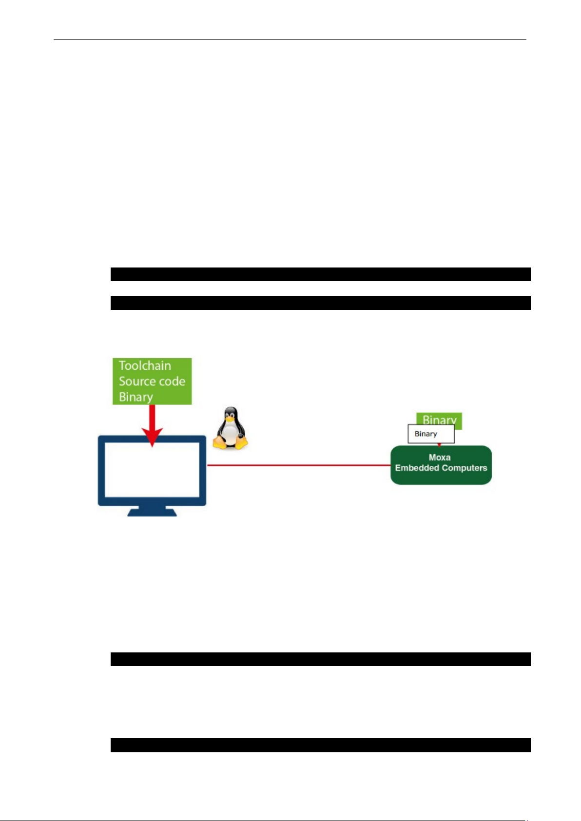
Arm-based Computer Linux Debian 9 UM Programmer’s Guide
7-2
moxa@Moxa:~$ sudo apt-get update
moxa@Moxa:~$ sudo apt-get install gcc build-essential flex bison automake
Building an Application
Introduction
Moxa’s Arm-based computers support both native and cross-compiling of code. Native compiling is more
straightforward since all the coding and compiling can be done directly on the device. However, Arm
architecture is less powerful and hence the compiling speed is slower. To overcome this, you can cross
compile your code on a Linux machine using a toolchain; the compiling speed is much faster.
Native Compilation
Follow these steps to update the package menu:
1. Make sure a network connection is available.
2. Use
3. Install the native compiler and necessary packages.
apt-get update to update the Debian package list.
Cross Compilation
Moxa Industrial Linux (MIL) in Moxa’s Arm-based computers is based on Debian. So, we recommend setting
up a Debian environment on the host device to ensure best compatibility during cross compilation.
The toolchain will need about 300 MB of hard disk space on your PC.
To cross compile your code, do the following:
1. Set up a Debian 9 environment using a VM or Docker.
2. Add the Moxa Debian repository to the apt source list.
Open moxa.source.list in the vi editor.
user@Linux:~$ sudo vi /etc/apt/sources.list.d/moxa.sources.list
Add the following line to moxa.source.list:
deb http://debian.moxa.com/debian stretch main contrib non-free
3. Update the apt information.
user@Linux:~$ apt-get update
Page 55

Arm-based Computer Linux Debian 9 UM Programmer’s Guide
7-3
user@Linux:~$ dpkg --add-architecture armhf
user@Linux:~$ apt-get install crossbuild-essential-armhf
user@Linux:~$ apt-get install libssl-dev:armhf
NOTE
For
#include <stdio.h>
}
4. (Optional) During the update process, if you don't want to see messages related to "server certificate
verification failed", you can install Moxa apt keyring. These messages, however, will not affect the
operation.
user@Linux:~$ apt-get install moxa-archive-keyring
5. Update the apt information again.
user@Linux:~$ apt-get update
6. In order to install non-amd64 packages, such as armhf and u386, add the external architecture.
In the example, we are adding the armhf architecture.
7. Download the toolchain file from apt server (all Moxa UC series computers use the official Debian
toolchain).
8. Install dev or lib packages depending on whether Debian or Moxa packages are applicable for the
procedure.
Example for installing a Moxa package:
user@Linux:~$ apt-get install libmoxa-uart-control-dev:armhf
Example for installing a Debian official package:
You can now start compiling programs using the toolchain.
all available libraries and headers offered by Debian, visit: https://packages.debian.org/index
Example Program—hello
In this section, we use the standard "hello" example program to illustrate how to develop a program for
Moxa computers. All example codes can be downloaded from Moxa’s website. The "hello" example code is
available in the hello folder; hello/hello.c:
int main(int argc, char *argv[])
{
printf("Hello World\n");
return 0;
Page 56

Arm-based Computer Linux Debian 9 UM Programmer’s Guide
7-4
moxa@Moxa:~$ gcc -o hello hello.c
moxa@Moxa:~$ strip -s hello
moxa@Moxa:~$ make
moxa@Moxa:~$ ./hello
Hello World
user@Linux:~$ arm-linux-gnueabihf-gcc -o hello \
user@Linux:~$ arm-linux-gnueabihf-strip -s hello
user@Linux:~$ make CC=arm-linux-gnueabihf-gcc \
STRIP=arm-linux-gnueabihf-strip
user@Linux:~$ scp hello moxa@192.168.3.127:~
moxa@Moxa:~$ ./hello
Hello World
Native Compilation
1. Compile the hello.c code.
or
use the Makefile as follows:
2. Run the program.
Cross Compiling
1. Compile the hello.c code.
hello.c
or
use the Makefile as follows:
2. Copy the program to a Moxa computer:
For example, if the IP address of your device used for cross compiling the code is "192.168.3.100" and
the IP address of the Moxa computer is "192.168.3.127", use the following command:
3. Run the hello.c program on the Moxa computer.
Page 57

Arm-based Computer Linux Debian 9 UM Programmer’s Guide
7-5
CC:=gcc
rm -f hello
CC:=arm-linux-gnueabihf-gcc
STRIP:=arm-linux-gnueabihf-strip
NOTE
Need to install Linux kernel header.
More information are available at Cryptodev
linux.org/documenta
Example Makefile
You can create a Makefile for the “hello" example program using the following code. By default, the Makefile
is set for native compiling.
"hello/Makefile":
STRIP:=strip
all:
$(CC) -o hello hello.c
$(STRIP) -s hello
.PHONY: clean
clean:
To set the hello.c program for cross compilation, modify the toolchain settings as follows:
Standard APIs
This section shows how to use some standard APIs on Moxa computers.
Cryptodev
The purpose of cryptographic hardware accelerator is to load off the intensive encryption/decryption and
compression/decompression tasks from CPU.
Cryptodev-linux is a device that allows access to Linux kernel cryptographic drivers; thus allowing the
userspace applications to take advantage of hardware accelerators. Cryptodev-linux uses "/dev/crypto"
interface to let kernel space hardware accelerator drivers become accessible from typical userspace
programs and libraries.
Example Code
The cryptodev example code is available in the cryptodev folder.
Cryptodev-linux APIs are defined in <crypto/cryptodev.h>.
tion.html
-linux document: http://cryptodev-
Page 58

Arm-based Computer Linux Debian 9 UM Programmer’s Guide
7-6
moxa@Moxa:~$ sudo modinfo ds1374_wdt
parm: timer_margin:Watchdog timeout in seconds (default 60s) (int)
options ds1374_wdt nowayout=1 timer_margin=60
Watchdog Timer (WDT)
The WDT works like a watchdog function. You can enable it or disable it. When the WDT is enabled, but the
application does not acknowledge it, the system will reboot. You can set the ack time from a minimum of 1
sec to a maximum of 1 day. The default timer is 60 seconds and the NO WAY OUT is enabled by default;
there is no way to disable the watchdog once it has been started. For this reason, if the watchdog daemon
crashes, the system will reboot after the timeout has passed.
Config
You need to know which driver you’re using first. Assume that the watchdog driver’s name is "ds1374_wdt",
then you can use the
filename: /lib/modules/4.4.0-cip-
uc5100+/kernel/drivers/watchdog/ds1374_wdt.ko
license: GPL
description: Maxim/Dallas DS1374 WDT Driver
author: Scott Wood <scottwood@freescale.com>
depends:
intree: Y
vermagic: 4.4.0-cip-uc5100+ mod_unload ARMv7 p2v8
parm: nowayout:Watchdog cannot be stopped once started, default=0 (bool)
The parameter’s name is "nowayout" for NO WAY OUT and "timer_margin" for timeout setting. To change
the setting, you can add a conf file under the directory "/etc/modprobe.d/". For example, add a file
"/etc/modprobe.d/watchdog.conf" with the following content:
modinfo command to check the information as follows:
This changes the setting for "ds1374_wdt" driver with nowayout=1 and timeout=60 seconds.
Example Code
The example code is available in the watchdog folder.
WDT driver APIs are used via "ioctl" through a file descriptor. The methods are defined in
<linux/watchdog.h>.
Page 59

Arm-based Computer Linux Debian 9 UM Programmer’s Guide
7-7
int fd = open("/dev/watchdog", O_WRONLY);
}
IOCTL Function
WDIOC_GETTIMEOUT
IOCTL Function
WDIOC_SETTIMEOUT
Description
Asks for the current status
ioctl(fd, WDIOC_GETSTATUS, &flags);
IOCTL Function
WDIOC_GETSUPPORT
NOTE
More information are available at Linux kernel docu
https://www.kernel.org/doc/Documentation/watchdog/watchdog
The watchdog device node locate at "/dev/watchdog".
if (fd < 0) {
perror("open watchdog failed");
exit(EXIT_FAILURE);
API List
IOCTL Function WDIOC_KEEPALIVE
Description Writes to the watchdog device to keep the watchdog alive
Example ioctl(fd, WDIOC_KEEPALIVE, 0);
Description Queries the current timeout
Example int timeout;
ioctl(fd, WDIOC_GETTIMEOUT, &timeout);
Description Modifies the watchdog timeout
Min: 1 second. Max: 1 day; Default: 60 seconds
Example int timeout = 60;
ioctl(fd, WDIOC_SETTIMEOUT, &timeout);
IOCTL Function WDIOC_GETSTATUS
Example int flags;
IOCTL Function WDIOC_SETOPTIONS
Description Control some aspects of the cards operation
• WDIOS_DISABLECARD: Turn off the watchdog timer
• WDIOS_ENABLECARD: Turn on the watchdog timer
• WDIOS_TEMPPANIC: Kernel panic on temperature trip
Example int options = WDIOS_DISABLECARD;
ioctl(fd, WDIOC_SETOPTIONS, &options);
Description Asks what the device can do
Example struct watchdog_info ident;
ioctl(fd, WDIOC_GETSUPPORT, &ident);
ment:
-api.txt
Page 60

Arm-based Computer Linux Debian 9 UM Programmer’s Guide
7-8
struct rtc_time {
};
NOTE
More information are available at Linux kernel document:
https://www.kernel.org/doc/Documentation/rtc.txt
Real-time Clock (RTC)
The Real-time Clock is a computer clock that keeps track of the current time. RTC can be used to complete
time critical tasks. Using RTC can benefit from its lower power consumption and higher accuracy.
Example Code
The RTC example code is available in the rtc folder.
RTC APIs are used via "ioctl" through a file descriptor. The methods are defined in <linux/rtc.h>.
The rtc device node locate at "/dev/rtc0".
The APIs that read time from RTC and set RTC time are using a structure "struct rtc_time". It is defined in
<linux/rtc.h>:
int tm_sec;
int tm_min;
int tm_hour;
int tm_mday;
int tm_mon;
int tm_year;
int tm_wday;
int tm_yday;
int tm_isdst;
API List
Note that variable "tm_mon" starts with 0 and variable "tm_year" represents the number of years since
1900.
IOCTL Function RTC_RD_TIME
Description Reads time information from the RTC; returns the value of argument 3
Example struct rtc_time rtc_tm;
ioctl(fd, RTC_RD_TIME, &rtc_tm);
IOCTL Function RTC_SET_TIME
Description Sets the RTC time. Argument 3 will be passed to the RTC.
Example struct rtc_time rtc_tm;
ioctl(fd, RTC_SET_TIME, &rtc_tm);
Page 61

Arm-based Computer Linux Debian 9 UM Programmer’s Guide
7-9
$ cd modbus/libmodbus-3.0.6/
$ ./configure && make install
$ cd modbus/libmodbus-3.0.6/tests/
$ ./unit-test-server tcp
$ cd modbus/libmodbus-3.0.6/tests/
$ ./unit-test-client tcp
NOTE
More information are available at libmodbus document: http://libmodbus.org/documentation/
NOTE
ECO Mode is only available in UC
required.
moxa@Moxa:~$ sudo mx-power-mgmt help
Modbus
The Modbus protocol is a messaging structure used to establish master-slave/client-server communication
between intelligent devices. It is a de facto standard, truly open, and the most widely used network protocol
in industrial manufacturing environments. It has been implemented by hundreds of vendors on thousands of
different devices to transfer discrete/analog I/O and register data between control devices.
Example Code
We use "libmodbus" with current stable version v3.0.6 as our modbus package. The package is also
available from the following link: http://libmodbus.org/releases/libmodbus-3.0.6.tar.gz
To run the test program, we first need to build the "libmodbus" library. We can build it simply by running
the following commands:
After build completes, the test program can be found at "tests" directory. The test program provides 3 types
of protocols (tcp/ tcppi/ rtu) which can be set by passing command line arguments.
The test program is client-server modeled. We should run the server program first, and then run the client
program from another terminal.
ECO Mode for Power Consumption
Moxa UC-3100 Series offers 3 operating modes: Active mode, Conservation mode, Scheduled Awakening
mode. These modes can be used to optimize power consumption, especially in remote deployments that lack
a stable power source. This section explains the procedure to set up the mx-power-mgmt utility to enable
the ECO mode.
Using mx-power-mgmt
To be able to run the mx-power-mgmt command, you must use sudo or run the command with the root
permission. Use the
# sudo mx-power-mgmt help command to display the menu page.
-3100 Series hardware v.1.0.0 and higher with firmware v1.2 and above
Usage:
mx-power-mgmt [Command]...
Command:
Page 62

Arm-based Computer Linux Debian 9 UM Programmer’s Guide
7-10
scheduled-awakening [time]
moxa@Moxa:~$
moxa@Moxa:~$ sudo mx-power-mgmt scheduled-awakening 30
management-utils/executable/scheduled_awakening)
Set system to scheduled-awakening mode.
[time]: a number in range 30 ~ 864000
conservation [time]
[time]: a number in range 30 ~ 864000
red-led [on|off|blink]
Set MCU red led
green-led [on|off]
Set MCU green led
wake-up
Wake up from conservation mode
mcu-upgrade
Upgrade MCU firmware
check-mode
Check MCU current mode
help
Show the usage manual
version
Show MCU firmware and utility version
Scheduled Awakening Mode
If this mode is enabled, the power input to the CPU and cellular module is temporarily cut off until the
scheduled wake-up duration (in seconds).
# sudo mx-power-mgmt scheduled-awakening 30
[sudo] password for moxa:
Execute user scheduled-awakening preinstall configuration (Command: /etc/power-
management-utils/config/scheduled_awakening_preinst)
Execute scheduled-awakening function configuration (Command: /etc/power-
Conservation Mode
If this mode is enabled, the CPU frequency is reduced to 300 MHz and all I/Os are turned Off except CAN
port for UC-3121. But, users can still turn on each I/O individually. The SYS LED will continue to blink as an
indication that the computer is under conservation mode.
The computer can be awakened from conservation mode according to the time you set. If you set the timer
to 0, the system will remain in the conservation mode until it is woken up by a
Wake-up Command.
Page 63

Arm-based Computer Linux Debian 9 UM Programmer’s Guide
7-11
moxa@Moxa:~$ sudo mx-power-mgmt conservation 30
moxa@Moxa:~$
moxa@Moxa:~$ sudo mx-power-mgmt conservation 0
Enter into conservation mode
Function
Command
# sudo mx-power-mgmt green-led on
# sudo mx-power-mgmt green-led off
Turn on the SYS Red LED
# sudo mx-power-mgmt red-led on
# sudo mx-power-mgmt red-led off
# sudo mx-power-mgmt red-led blink
moxa@Moxa:~$ sudo mx-power-mgmt wake-up
moxa@Moxa:~$
# sudo mx-power-mgmt conservation 30
[sudo] password for moxa:
Execute user conservation preinstall configuration (Command: /etc/power-
management-utils/config/conservation_preinst)
Execute conservation function configuration (Command: /etc/power-management-
utils/executable/conservation)
Network already stopped
Clearing state...
# sudo mx-power-mgmt conservation 0
Execute user conservation preinstall configuration (Command: /etc/power-
management-utils/config/conservation_preinst)
Execute conservation function configuration (Command: /etc/power-management-
utils/executable/conservation)
WARNING: If you set timer as 0, it will not wake up automatically
You need to use '# mx-power-mgmt wake-up' command to wake up system by yourself
Do you want to continue? (N/y)
y
Setting the SYS LEDs Using mx-power-mgmt
The SYS LEDs in the UC-3100 computer are connected both to the system and the power management MCU.
Hence, you can control the MCU to set the SYS LED through the
LEDs on the MCU: Green and Red. Before turning on/off the LEDs using the
sure that the SYS LEDs are turned off on the system side using the command
. You can then use the following mx-power-mgmt commands to control the SYS LEDs.
off
Turn on the SYS Green LED
Turn off the SYS Green LED
Turn off the SYS Red LED
Set the SYS Red LED to the blinking mode
Wake-up From Conservation Mode
The computer can be awakened from the Conservation mode according to a time interval that you set. If
you set the timer interval to 0, the computer will stay in this mode until it is woken up using the
mx-power-mgmt wake-up
Execute conservation wake up function configuration (Command: /etc/power-
management-utils/executable/conservation_wake_up)
Execute user conservation wake up postinst configuration (Command: /etc/power-
management-utils/config/conservation_wake_up_postinst)
command.
mx-power-mgmt utility. There are two SYS
mx-power-mgmt utility, make
# mx-led-ctl -p 1 -i 1
# sudo
Page 64

Arm-based Computer Linux Debian 9 UM Programmer’s Guide
7-12
moxa@Moxa:~$ sudo mx-power-mgmt mcu-upgrade
moxa@Moxa:~$
moxa@Moxa:~$ sudo mx-power-mgmt check-mode
moxa@Moxa:~$
moxa@Moxa:~$ sudo mx-power-mgmt version
moxa@Moxa:~$
# System Leds
CONFIG_POWER_OFF_ETHERNET_ETH1=y
MCU Firmware Upgrade
If there is a new version of the MCU firmware, the system will automatically update the MCU after a reboot
following the update of the system using the
commands. You can also manually update the MCU firmware with the following command:
# sudo mx-power-mgmt mcu-upgrade
Start to upgrade MCU firmware
MCU enter into BSL mode.
Reset MCU
MCU firmware upgrade completed
apt-get dist-upgrade and apt-get upgrade
Checking the MCU mode
MCU has four modes: power on, active, scheduled-awakening, and conservation. In general, the power on
mode is equivalent to active mode. The difference is that active means that your system is awakened from
conservation or scheduled-awakening.
# sudo mx-power-mgmt check-mode
active mode
Viewing the Utility and MCU Firmware Version
# sudo mx-power-mgmt version
MCU firmware version 1.0.0S04
mx-power-mgmt version 1.0.0
User-defined Actions
The mx-power-mgmt utility allows customers to specify the I/O peripherals that they want to turn off in
the conservation mode (this will affect the power consumption). The utility also supports the execution of
user programs before entering the Conservation and Scheduled Awakening modes or start a service to keep
a program running after wake-up.
To specify the I/O peripheral that you want to turn off in the conservation mode, modify the following file:
# vi /etc/power-management-utils/config/conservation_config
CONFIG_TURN_OFF_LED=y
# System Loading
CONFIG_STOP_WIFI_SIGNALD_SERVICE=y
CONFIG_STOP_CELLULAR_SIGNALD_SERVICE=y
CONFIG_STOP_PUSH_BUTTON_SERVICE=y
CONFIG_LOW_CPU_FREQUENCY=y
# Ethernet
CONFIG_POWER_OFF_ETHERNET_ETH0=y
Page 65

Arm-based Computer Linux Debian 9 UM Programmer’s Guide
7-13
# Cellular Wireless
CONFIG_POWER_SAVE_WIFI=y
int num_of_interfaces;
}
CONFIG_TURN_OFF_CELLULAR_USB=y
CONFIG_POWER_OFF_CELLULAR=y
# Others
CONFIG_TURN_OFF_USB_BUS=y
CONFIG_PULL_DOWN_GPIO=y
# Wake Up Time
CONFIG_DEFAULT_WAKE_UP_TIME=30
# WiFi Wireless (For UC-3111-LX and UC-3121-LX series model)
To run your own program to back up or shut down your service(s) before entering the Conservation or
Scheduled Awakening, edit the following files.
# vi /etc/power-management-utils/config/conservation_preinst
# vi /etc/power-management-utils/config/scheduled_awakening_preinst
To start a service to keep your program running after the system wake-up from Conservation or Scheduled
Awakening mode, edit the following files:
e.g. # vi /etc/power-management-utils/config/conservation_wake_up_postinst
e.g. # vi /etc/power-management-utils/config/scheduled_awakening_wake_up_postinst
Moxa Platform Libraries
Moxa provides several libraries for developing customized applications. In this section, we will show how to
utilize these libraries.
Example codes are available at: https://github.com/Moxa-Linux
Error Numbers
Moxa defines exclusive error numbers for Moxa libraries. It works with other Moxa library codes, and is
useful for checking the result of executing an API.
If you call an API, you can check the return value to take particular action in response.
ret = mx_get_number_of_interfaces(&num_of_interfaces);
if (ret == E_SYSFUNCERR){
// do something...
Usage
• Need package "libmoxa-errno-dev"
• Include header <mx_errno.h>
Page 66

Arm-based Computer Linux Debian 9 UM Programmer’s Guide
7-14
Name
Value
Description
E_INVAL
-2
Invalid input
E_BUZZER_PLAYING
-30
The buzzer is already playing
moxa@Moxa:~$ sudo apt-get install \
libmoxa-platform-info-dev
Error Number List
E_SUCCESS 0 Exit successfully
E_SYSFUNCERR -1 Error occurs in system functions (e.g. open)
E_LIBNOTINIT -3 Library is not initialized
E_UNSUPCONFVER -4 Config version is not supported for the library
E_CONFERR -5 Error in config file
E_GPIO_NOTEXP -20 The GPIO is not exported
E_GPIO_UNKDIR -21 Unknown GPIO direction get
E_GPIO_UNKVAL -22 Unknown GPIO value get
E_UART_NOTOPEN -50 The UART port is not opened
E_UART_GPIOIOCTLINCOMP -51 GPIO and IOCTL are incompatible for UART
E_UART_UNKMODE -52 Unknown UART mode get
E_UART_EXTBAUDUNSUP -53 Extended baudrate is not supported
E_PBTN_NOTOPEN -70 The push button is not opened
Platform Information
Moxa platform info library is used to get information of interfaces on the device, which is useful to know the
device’s capability before developing applications.
Usage
• Install the package "libmoxa-platform-info-dev"
("libjson-c-dev" package will be installed automatically when install "libmoxa-platform-info-dev")
• Include header <mx_platform_info.h> and <json-c/json.h>
• Link the libraries "-ljson-c" and "-lmx_platform_info" while compiling
API List
Function Prototype int mx_get_number_of_interfaces(int *num_of_interfaces);
Description Get the number of interfaces supported on the device
Parameters • num_of_interfaces: a pointer which points to a place for storing output value
Return Value • 0 on success
• negative integers as error number
Example int num_of_interfaces; mx_get_number_of_interfaces(&num_of_interfaces);
Function Prototype int mx_get_platform_interface(char ***profiles);
Description Get the interfaces supported on the device
Parameters • profiles: a pointer which points to a place for storing output value
the list of platform interfaces, in "char **" format.
Return Value • 0 on success
• negative integers as error number
Example char **profiles;
mx_get_platform_interface(&profiles);
e.g. { "led-control", … }
Page 67

Arm-based Computer Linux Debian 9 UM Programmer’s Guide
7-15
NOTE
moxa@Moxa:~$ sudo apt-get install \
libmoxa-buzzer-control-dev
Function Prototype int mx_free_platform_interface(char **profiles);
Description Free the memory space of profiles allocated by "mx_free_platform_interface" API
Parameters • profiles: profiles from "mx_free_platform_interface" API
Return Value • 0 on success
• negative integers as error number
Example mx_free_platform_interface(profiles);
Function Prototype int mx_get_profile(const char *interface, struct json_object **profile);
Description Get the profile of target interface
Parameters • interface: the name of the target interface
"buzzer-control"
"dio-control"
"uart-control"
"led-control"
"push-button"
• profile: a pointer which points to a place for storing output value
Return Value • 0 on success
• negative integers as error number
Example struct json_object *profile;
mx_get_profile("led-control", &profile);
Buzzer
Moxa buzzer control library can be used to control the buzzer on the device. We provide interfaces for
controlling the buzzer to beep for a certain period or keep beeping till it is switched off.
Moxa buzzer control library should be used carefully, the buzzer must be stopped before the process
The Moxa buzzer control library is supported only in the UC-8100A-ME-T Series.
Usage
• Need package "libmoxa-buzzer-control-dev"
• Include header <mx_buzzer.h>
• Link library "-lmx_buzzer_ctl" while compiling
API List
Function Prototype int mx_buzzer_init(void);
Description Initialize Moxa buzzer control library
Parameters N/A
Return Value • 0 on success
Example mx_buzzer_init();
ends. Or the buzzer may beep without control.
• negative integers as error number
Page 68

Arm-based Computer Linux Debian 9 UM Programmer’s Guide
7-16
Example
mx_buzzer_play_sound(3);
Description
Stop the buzzer
moxa@Moxa:~$ sudo apt-get install \
libmoxa-dio-control-dev
Description
Initialize Moxa DIO control library
Function Prototype int mx_buzzer_play_sound(unsigned long duration);
Description Play the buzzer
Parameters • duration: the duration time in seconds
range: 1-60
0 for keep beeping
Return Value • 0 on success
• negative integers as error number
Function Prototype int mx_buzzer_stop_sound(void);
Parameters N/A
Return Value • 0 on success
• negative integers as error number
Example mx_buzzer_stop_sound();
Digital I/O
Usage
API List
Moxa DIO control library can be used to control digital I/O interface. Including getting states from Direct
Input and Output ports, setting state of Direct Output ports.
• Need package "libmoxa-dio-control-dev"
• Include header <mx_dio.h>
• Link library "-lmx_dio_ctl" while compiling
• Need to call "mx_dio_init" before using other APIs
Function Prototype int mx_dio_init(void);
Parameters N/A
Return Value • 0 on success
• negative integers as error number
Example mx_dio_init();
Function Prototype int mx_dout_set_state(int doport, int state);
Description Set state for target Direct Output port
Parameters • doport: target DOUT port number
• state:
DIO_STATE_LOW: low
DIO_STATE_HIGH: high
Return Value • 0 on success
• negative integers as error number
Example mx_dout_set_state(0, DIO_STATE_HIGH);
Page 69

Arm-based Computer Linux Debian 9 UM Programmer’s Guide
7-17
mx_dout_get_state(0, &state);
Description
Get state from target Direct Input port
Description
Set an action for an event occurred of target Direct Input port
Function Prototype int mx_dout_get_state(int doport, int *state);
Description Get state from target Direct Output port
Parameters • doport: target DOUT port number
• state: a pointer which points to a place for storing output value
Return Value • 0 on success
• negative integers as error number
Example int state;
Function Prototype int mx_din_get_state(int diport, int *state);
Parameters • diport: target DIN port number
• state: a pointer which points to a place for storing output value
Return Value • 0 on success
• negative integers as error number
Example int state;
mx_din_get_state(0, &state);
Function Prototype int mx_din_set_event(int diport, void (*func)(int diport), int mode,
unsigned long duration);
Parameters • diport: target DIN port number
• func: a function pointer which will be invoked on DIN event detected
• mode: DIN event mode
DIN_EVENT_CLEAR
DIN_EVENT_LOW_TO_HIGH
DIN_EVENT_HIGH_TO_LOW
DIN_EVENT_STATE_CHANGE
• duration: The during time that the event occurred to trigger action
range: 40 - 3600000 (ms)
0 means no duration
Return Value • 0 on success
• negative integers as error number
Example void (*fp)(int );
mx_din_set_event(0, fp, DIN_EVENT_STATE_CHANGE, 100);
Function Prototype int mx_din_get_event(int diport, int *mode, unsigned long *duration);
Description Get event setting of target Direct Input port
Parameters • diport: target DIN port number
• mode: a pointer which points to a place for storing output value
• duration: a pointer which points to a place for storing output value
Return Value • 0 on success
• negative integers as error number
Example int mode;
unsigned long duration;
mx_din_get_event(0, &mode, &duration);
Page 70

Arm-based Computer Linux Debian 9 UM Programmer’s Guide
7-18
moxa@Moxa:~$ sudo apt-get install \
libmoxa-uart-control-dev
UART
Moxa UART can be used to set the mode of UART ports and transmit data via UART ports.
Usage
• Need package "libmoxa-uart-control-dev"
• Include header <mx_uart.h>
• Link library "-lmx_uart_ctl" while compiling
• Need to call "mx_uart_init" before using other APIs
API List
Function Prototype int mx_uart_init(void);
Description Initialize Moxa UART control library
Parameters N/A
Return Value • 0 on success
• negative integers as error number
Example mx_uart_init();
Function Prototype int mx_uart_set_mode(int port, int mode);
Description Set mode of target UART port
Parameters • port: target UART port
• mode:
UART_MODE_RS232
UART_MODE_RS485_2W
UART_MODE_RS422_RS485_4W
Return Value • 0 on success
• negative integers as error number
Example mx_uart_set_mode(0, UART_MODE_RS232);
Function Prototype int mx_uart_get_mode(int port, int *mode);
Description Get mode of target UART port
Parameters • port: target UART port
• mode: a pointer for storing output
Return Value • 0 on success
• negative integers as error number
Example int mode;
mx_uart_get_mode(0, &mode);
Function Prototype int mx_uart_open(int port);
Description Open target UART port
Parameters • port: target UART port
Return Value • 0 on success
• negative integers as error number
Example mx_uart_open(0);
Page 71

Arm-based Computer Linux Debian 9 UM Programmer’s Guide
7-19
Function Prototype
int mx_uart_read(int port, char *data, size_t count);
Function Prototype
int mx_uart_write(int port, char *data, size_t count);
Function Prototype
int mx_uart_set_baudrate(int port, int baudrate);
mx_uart_get_baudrate(0, &baudrate);
Function Prototype int mx_uart_close(int port);
Description Close target UART port
Parameters • port: target UART port
Return Value • 0 on success
• negative integers as error number
Example mx_uart_close(0);
Description Read data from target UART port
Parameters • port: target UART port
• data: memory location of data to be stored
• count: read size
Return Value • positive integers means size of data read
• negative integers as error number
Example char data[256];
mx_uart_read(0, data, 256);
Description Write data from target UART port
Parameters • port: target UART port
• data: memory location of data to be written
• count: write size
Return Value • positive integers means size of data read
• negative integers as error number
Example char data[256];
mx_uart_read(0, data, 256);
Description Set the baudrate of target UART port
Parameters • port: target UART port
Return Value • 0 on success
Example mx_uart_set_baudrate(0, 115200);
Function Prototype int mx_uart_get_baudrate(int port, int *baudrate);
Description Get the baudrate of target UART port
Parameters • port: target UART port
Return Value • 0 on success
Example int baudrate;
• baudrate: The baudrate
• negative integers as error number
• baudrate: a pointer which points to a place for storing output value
• negative integers as error number
Page 72

Arm-based Computer Linux Debian 9 UM Programmer’s Guide
7-20
Function Prototype
int mx_uart_set_stopbits(int port, int bits);
mx_uart_get_stopbits(0, &bits);
Description
Set the parity of target UART port
Function Prototype
int mx_uart_get_parity(int port, int *parity);
Function Prototype int mx_uart_set_databits(int port, int bits);
Description Set the data bits of target UART port
Parameters • port: target UART port
• bits: The data bits
Return Value • 0 on success
• negative integers as error number
Example mx_uart_set_databits(0, 8);
Function Prototype int mx_uart_get_databits(int port, int *bits);
Description Get the data bits of target UART port
Parameters • port: target UART port
• bits: a pointer which points to a place for storing output value
Return Value • 0 on success
• negative integers as error number
Example int bits;
mx_uart_get_databits(0, &bits);
Description Set the stop bits of target UART port
Parameters • port: target UART port
• bits: The stop bits
Return Value • 0 on success
• negative integers as error number
Example mx_uart_set_stopbits(0, 1);
Function Prototype int mx_uart_get_stopbits(int port, int *bits);
Description Get the stop bits of target UART port
Parameters • port: target UART port
• bits: a pointer which points to a place for storing output value
Return Value • 0 on success
• negative integers as error number
Example int bits;
Function Prototype int mx_uart_set_parity(int port, int parity);
Parameters • port: target UART port
• parity: The parity
Return Value • 0 on success
• negative integers as error number
Example mx_uart_set_parity(0, 0);
Description Get the parity of target UART port
Parameters • port: target UART port
• parity: a pointer which points to a place for storing output value
Return Value • 0 on success
• negative integers as error number
Example int parity;
mx_uart_get_parity(0, &parity);
Page 73

Arm-based Computer Linux Debian 9 UM Programmer’s Guide
7-21
moxa@Moxa:~$ sudo apt-get install \
libmoxa-led-control-dev
Parameters
N/A
Function Prototype
int mx_led_get_num_of_groups(int led_type, int *num_of_groups);
LED
LED APIs can control the LEDs on the device, which can be ON, OFF, or BLINK. LEDs on a device are
separated to types and groups. There are 2 types of LED: Signal LED and Programmable LED. Each type
may contain several groups, and each group may contain several LEDs.
Usage
• Install package "libmoxa-led-control-dev"
• Include the header <mx_led.h>
• Link the library "-lmx_led_ctl" while compiling
• Call "mx_led_init" before using other APIs
API List
Function Prototype int mx_led_init(void);
Description Initialize Moxa LED control library
Return Value • 0 on success
Example mx_led_init();
Description Get the number of groups of a LED type
Parameters • led_type:
Return Value • 0 on success
Example int num_of_groups;
Function Prototype int mx_led_get_num_of_leds_per_group(int led_type, int
Description Get the number of LEDs per group of a LED type
Parameters • led_type:
Return Value • 0 on success
Example int num_of_leds_per_group;
• negative integers as error number
LED_TYPE_SIGNAL or LED_TYPE_PROGRAMMABLE
• num_of_groups: a pointer which points to a place for storing output value
• negative integers as error number
mx_led_get_num_of_groups(LED_TYPE_SIGNAL, &num_of_groups);
*num_of_leds_per_group);
LED_TYPE_SIGNAL or LED_TYPE_PROGRAMMABLE
• num_of_leds_per_group: a pointer which points to a place for storing output
value
• negative integers as error number
mx_led_get_num_of_leds_per_group(LED_TYPE_SIGNAL,
&num_of_leds_per_group);
Page 74

Arm-based Computer Linux Debian 9 UM Programmer’s Guide
7-22
Function Prototype
int mx_led_set_all_off(void);
Example
mx_led_set_all_off();
Description
Set all LED on
moxa@Moxa:~$ sudo apt-get install \
libmoxa-push-button-dev
NOTE
Remember to terminate the push button daemon that run by the
some system functions which defined in the daemon when testing the button.
The push button daemon is called
stop moxa-push-button
Function Prototype int mx_led_set_brightness(int led_type, int group, int index, int state);
Description Set LED state on, off, blink
Parameters • led_type:
LED_TYPE_SIGNAL or LED_TYPE_PROGRAMMABLE
• group: group number
• index: LED index
• state:
LED_STATE_OFF or LED_STATE_ON or LED_STATE_BLINK
Return Value • 0 on success
• negative integers as error number
Example mx_led_set_brightness(LED_TYPE_PROGRAMMABLE, 1, 1, LED_STATE_ON);
Description Set all LED off
Parameters N/A
Return Value • 0 on success
• negative integers as error number
Function Prototype int mx_led_set_all_on(void);
Parameters N/A
Return Value • 0 on success
Example mx_led_set_all_on();
Push Button
Push button APIs.
Usage
• Need package "libmoxa-push-button-dev"
• Include header <mx_pbtn.h>
• Link library "-lmx_push_btn" while compiling
• Need to call "mx_pbtn_init" before using other APIs
• negative integers as error number
moxa-pbtnd. You can terminate the process by using the systemctl
command.
system. Or you might accidentally trigger
Page 75

Arm-based Computer Linux Debian 9 UM Programmer’s Guide
7-23
Function Prototype
int mx_pbtn_init(void);
Example
mx_pbtn_init();
Description
Open a push button by button type and index
btn_id = mx_pbtn_open(BUTTON_TYPE_USER, 1);
Description
Close a push button
API List
Description Initialize Moxa push button library
Parameters N/A
Return Value • 0 on success
• negative integers as error number
Function Prototype int mx_pbtn_open(int type, int index);
Parameters • type:
BUTTON_TYPE_SYSTEM or BUTTON_TYPE_USER
• index: button index
Return Value • negative integers as error number
• 0 or positive integer: button ID for manipulate the button by other APIs
Example int btn_id;
Function Prototype int mx_pbtn_close(int btn_id);
Parameters • btn_id: button ID returned by "mx_pbtn_open"
Return Value • 0 on success
Example mx_pbtn_close(0);
Function Prototype int mx_pbtn_start(int btn_id);
Description Start listening on a push button
Parameters • btn_id: button ID returned by "mx_pbtn_open"
Return Value • 0 on success
Example mx_pbtn_start(0);
Function Prototype int mx_pbtn_stop(int btn_id);
Description Stop listening on a push button
Parameters • btn_id: button ID returned by "mx_pbtn_open"
Return Value • 0 on success
Example mx_pbtn_stop(0);
Function Prototype int mx_pbtn_wait(void);
Description Check if there is any button being listened on, if so, hang the process. This API can
Parameters N/A
Return Value • 0 on success
Example mx_pbtn_wait();
• negative integers as error number
• negative integers as error number
• negative integers as error number
be used for daemon.
• negative integers as error number
Page 76

Arm-based Computer Linux Debian 9 UM Programmer’s Guide
7-24
Function Prototype
int mx_pbtn_released_event(int btn_id, void (*func)(int));
duration);
mx_pbtn_hold_event(0, fp, 60);
Function Prototype int mx_pbtn_is_pressed(int btn_id);
Description Get the state of a button
Parameters • btn_id: button ID returned by "mx_pbtn_open"
Return Value • negative integers as error number
• 0 if the button is released
• 1 if the button is pressed
Example mx_pbtn_is_pressed(0);
Function Prototype int mx_pbtn_pressed_event(int btn_id, void (*func)(int));
Description Register action on button pressed
Parameters • btn_id: button ID returned by "mx_pbtn_open"
• func: a function pointer which will be invoked on button pressed
Return Value • 0 on success
• negative integers as error number
Example void (*fp)(int );
mx_pbtn_pressed_event(0, fp);
Description Register action on button released
Parameters • btn_id: button ID returned by "mx_pbtn_open"
• func: a function pointer which will be invoked on button released
Return Value • 0 on success
• negative integers as error number
Example void (*fp)(int );
mx_pbtn_released_event(0, fp);
Function Prototype int mx_pbtn_hold_event(int btn_id, void (*func)(int), unsigned long
Description Register action on button hold
Parameters • btn_id: button ID returned by "mx_pbtn_open"
• func: a function pointer which will be invoked on button hold
• duration: the time that button being hold to trigger action (in seconds)
range: 1-3600
0 for keep triggering every second
Return Value • 0 on success
• negative integers as error number
Example void (*fp)(int );
 Loading...