

Moving Terrain MT-VisionAir X ETSO, MTUP/00-3.60-3 Installation Manual
Moving Terrain
Installation Manual MT-VisionAir X ETSO
PN MTUP/00-3.60-3
Revision 0
MTUX/IA-63-00 – Installation Manual
Date: 2017/02/17

MTUX/IA-63-00 – Installation Manual 2 Date: 2017/02/17
Note on this manual
While every precaution has been taken in preparing the contents of this
manual, errors and omissions cannot be completely ruled out. The publisher
and the authors can in no way be held responsible or made legally liable for
any such errors or their potential consequences. The publisher is grateful for
any suggestions for improvement and for pointing out any errors.
WARRANTY AND LIABILITY ADVICE
The software is to facilitate your terrestic navigation only. It is not a certied
aviation equipment and does not replace any aircraft instrument. You are
explicitly cautioned to verify that the hardware employed is functioning
correctly and does not interfere with the aircraft or other vessel in a hazardous
manner. Data errors and computer errors are possible. This also pertains
to the IFR data and procedures implied in the respective modules. Human
error can make the moving map, navdata or any supplemental information
incorrect. The pilot in command remains the nal authority on the accuracy
and sufciency of the hardware and software.
Warranty and Liability Disclaimer:
The manufacturer, distributor or sales agent resume no liability as to the
correct function of the software, the availability of a reference signal (GPS) or
the validity of the charts, navdata or any supplemental information like airport
information a.o. Never will the manufacturer, producer, sales representative
and neither of their staff be liable to you for any consequential incidential or
indirect damages (including damages for loss of business prots, business
interruption, loss of business information and the like) arising from the use
of or inability to use the software even if any of the staff mentioned above
has been advised.
There is no warranty, express or implied, including without limitation the
implied warranties of merchantability and tness for a particular purpose,
regarding the software. The entire risk as to the results and performance of
the hardware and software is assumed by you.
MTUX/IA-63-00 – Installation Manual
3Date: 2017/02/1700
***
Moving Terrain is a registered trademark of:
Moving Terrain AG
Sparenberg 1
D-87477 Sulzberg
Tel: +49 8376 9214-11
Fax: +49 8376 9214-14
(c) Copyright
AirPlus Maintenance GmbH
Flughafen 28
Tel. +49 (0)7541-38878-0 Fax -34218
D-88046 Friedrichshafen
P/N of the installation manual for MTEP/00-3.60-2 used to be MTUP/17-02.
New P/N for MT-VisionAir X ETSO: MTEP/00-3.60-3
MT UX/IA-63-00
Revision
Item within the category
Category (i.e. installation accessories)
Sub type = MT-VisionAir X ETSO
MT = Moving Terrain (brand)
Revision Status
Date Changes / Additions / Corrections Revision Valid Pages
2017/02/17 1st edition for MT-VisionAir X ETSO 0 146

MTUX/IA-63-00 – Installation Manual
4 Date: 2017/02/17
Contents
1. General information for Operating a MT-VisionAir X ETSO ... 13
2. Introduction of MT-VisionAir X ETSO ............................................ 14
2.1 Views of device .................................................................................14
2.2 LabelDenition&SerialNumber ....................................................
16
2.3 Warning Sign for Cockpit .................................................................
17
3. Installation of MT-VisionAir X ETSO............................................... 18
3.1 Installation of Easy mount in the cockpit panel .............................18
3.1.1 Choosing the best location .............................................................
18
3.1.2 Easy mount sketch .........................................................................
18
3.1.3 Panel cutout ....................................................................................
19
3.2.4 Dimensions of Easy mount .............................................................
20
3.1.5 Dimensions of MT-VisionAir X ETSO
with Easy mount .................. 23
3.1.6 Remarks regarding installation .......................................................
25
3.1.7 View of an installation in a cockpit ..................................................
26
3.1.8 Removal and Insertion of the Device ..............................................
26
3.2 Installation of the Easy mount in other locations ..........................
27
4. Installation of GPS ........................................................................... 29
4.1 Installation of Fast Integral GPS ......................................................29
4.1.1 Recommended installation location of the Fast Integral GPS ........
29
4.1.2 View of Fast Integral GPS ..............................................................
31
4.1.3 External dimensions of Fast Integral GPS ......................................
32
4.1.4 Remarks regarding installation .......................................................
33
4.3 Restrictions for Location of Fast Integral GPS and iridium
antenna .......................................................................................................34
5. Connections ..................................................................................... 35
5.1 Power supply ....................................................................................35
5.2 Power supply via battery pack ........................................................
36
5.3 General connection of MT-VisionAir X ETSO .................................
37
5.4 Central connector (50-pin MDR) ......................................................
38
5.5 Pin layout of the central connector (50-pin MDR) ..........................
40
5.6 The central plug cable assembly for MT-VisionAir X ETSO ..........
42
5.6.1. Recommended tools and materials ................................................42
5.6.2. The strain relief ...............................................................................42

MTUX/IA-63-00 – Installation Manual
5Date: 2017/02/1700
5.6.3. Strip the cable and solder to the connector pins .............................43
5.6.4. The grounding .................................................................................44
5.7 Standard/test connection with MDR50 central connector ............
46
5.7.1 Standard/test cabling when system is delivered w/o COM / USB
connections ...............................................................................................46
5.7.2 Connection of further COM / USB devices to central connector .....
46
5.7.3 Optional 220 V power supply with central connector ......................
47
5.8 MT-VisionAir X ETSO starts automatically as soon as power is
connected ...................................................................................................47
5.9 Adjust the brightness of the screen ................................................
47
5.8 Connecting GPS to the system .......................................................
48
5.8.1 Fast Integral GPS ...........................................................................
48
5.8.2 Connecting another type of GPS ....................................................
48
6. Crosslloptions ............................................................................... 49
6.1 CrossllfromGarmin430/530 ....................................................... 49
6.1.1 System description ........................................................................
49
6.1.2 Prerequisites ...................................................................................
49
6.1.3 Congurations and usage ...............................................................
49
6.1.4. Limitations .......................................................................................51
6.2. Transmission and Displaying of a User Route from an External
Flightplanning Program ............................................................................52
6.2.1 System description ........................................................................
52
6.2.2 Installation advice for USB port .....................................................
52
6.2.3 Prerequisites ..................................................................................
52
6.2.4 Usage (see User manual) ...............................................................
52
6.2.5 Error Messages using IMPORT Function .......................................
52
7. Software Updates, OS Upgrade, Backup of User Data ................. 53
7.1 Information about the system ..........................................................53
7.2 Software Update / Update of Charts and Data ...............................
54
7.2.1 Prerequisites ...................................................................................
54
7.2.2 Procedure .......................................................................................
54
7.3 Upgrade of the Operating System ...................................................
55
7.3.1 Prerequisites ..................................................................................
55
7.3.2 Info CPU Type ................................................................................
55
7.3.3 Procedure .......................................................................................
55
7.4 Backup of User Data .........................................................................
56
7.4.1 Prerequisites ...................................................................................
56
7.4.2 Procedure .......................................................................................
56
7.4.3 Error Message ................................................................................
57

MTUX/IA-63-00 – Installation Manual 6 Date: 2017/02/17
7.5 Restore of User Data ........................................................................57
7.5.1 Procedure .......................................................................................
57
8. Entries in mtpro.ini - general info ................................................... 58
9. MT Satellite Radar and MT B
LITZPLAN .............................................. 59
9.1 System components for data transfer (Hardware/Software) ........ 59
9.1.1 Telephone connection .....................................................................
59
9.1.2 GPS receiver ..................................................................................
60
9.2 Connection of system components for data transfer ...................
61
9.2.1 Block diagram of system components ............................................
61
9.2.2 Connection options and Limitations ................................................
61
9.3 Datalink Overview .............................................................................
62
9.3.1 Datalink status infoblock .................................................................
62
9.3.2 Loss of communication with phone or modem ...............................
63
9.3.3 RADAR usage: Manual download / Live update .............................
64
9.4 Satellite Phones ................................................................................
65
9.4.1 Thuraya XT-PRO ............................................................................
65
9.4.2 Iridium 9555 ....................................................................................
65
9.4.3 Installation of modied antenna adapter for Iridium 9555 ...............
66
9.4.3 Iridium 9575 ....................................................................................
67
9.5 Installation of the iridium antenna .................................................
68
9.5.1 Recommended installation location of the iridium antenna ............
68
9.5.2 Extension of the antenna cable ......................................................
68
9.5.3 Recommended solution of external antenna for Thuraya
communication ..........................................................................................69
9.5.4 Solutions for improving reception ...................................................
69
9.5.5 Example for an internal installation .................................................
69
9.5.6 ITAS module for MT-Mission Management System ........................
70
9.5.7 Advice for certication tests ............................................................
70
9.6 To adjust of the telephone connection(s) (in the software) ..........
71
9.6.1 Authorization for download of radar data ........................................
71
9.6.2 Selection of the telephone connection (in the software) .................
72
9.7 Test of radar data download: MT Satellite Radar (Enhanced) ......
73
9.7.1 Download of radar data for MT Satellite Radar (standard) .............
74
9.7.2 Download of radar data for MT Satellite Radar Enhanced .............
77
9.7.3 Download messages in detail .........................................................
79
9.7.4 Overview: RADAR download statuses, messages and timings ......
82
9.7.5 Download test completed ...............................................................
86
9.8 Test of MT B
LITZPLAN connection ......................................................88

MTUX/IA-63-00 – Installation Manual
7Date: 2017/02/1700
10. MT TCAD Interfaces ......................................................................... 90
10.1 MT TCAD Interface for Avidyne TAS600 series ..............................90
10.1.1 System components Avidyne TAS600 series ...............................
90
10.1.2 Avidyne TAS600 series standard installation of antennas ............
91
10.1.3 Avidyne TAS600 series installation recommendations for serial
antennas (head antennas) ........................................................................92
10.1.4 Avidyne TAS600 series installation recommendations for parallel
antennas (lower antennas) .......................................................................93
10.1.5 Avidyne TAS600 series non-standard installation of antennas .....
93
10.1.6 Connection TCAD (Avidyne TAS600 series) ................................
94
10.1.7 Pin assignment COM 1 port for MT-VisionAir X ETSO devices ....
96
10.1.8 Conguration for the operation of the Avidyne TAS600 series with
Moving Terrain ..........................................................................................96
10.1.9 Selection of the TAS source in MT program .................................
97
10.1.10 ......................................................................................................
Entry in mtpro.ini .......................................................................................97
10.1.11 Testing of Avidyne TAS600 series ...............................................
97
10.2 MT-PowerFLARM Interface ..............................................................
99
10.2.1 Connector layout for RS232 Connector on Powerarm Core: ......
99
10.2.2 Adjustments for connection to MT VisionAir X ..............................
99
10.2.3 Connection to 50-pin MDR central connector for MT-VA X ...........
100
10.2.4 Entry in mtpro.ini ...........................................................................
100
10.2.5 Settings in MT program ................................................................
100
10.2.6 Activating of PowerFLARM trafc warning ....................................
100
10.2.7 Testing of PowerFLARM interface ................................................
101
10.3 Combination of Avidyne TAS600 series Interface with PowerFLARM
Interface ......................................................................................................103
10.3.1 Requirements for parallel use of interfaces ..................................
103
10.3.2 Entry in mtpro.ini ...........................................................................
103
10.3.3 Connections to TAS sensors .........................................................
103
10.3.4 Inital operation of the combined signal interface of Avidyne/Ryan TAS
signal with PowerFLARM signal ...............................................................104
10.4 GARRECHT TRX1090 Interface .......................................................
104
11. MT Stormscope ................................................................................ 105
11.1 System components ......................................................................... 105
11.2 Block diagram ...................................................................................
105
11.3 Pin Assignment ................................................................................
105
11.4 Entry in mtpro.ini ..............................................................................
105

MTUX/IA-63-00 – Installation Manual
8 Date: 2017/02/17
12. MT-VGA-Output Device for external screens ................................ 106
12.1 Technical description ......................................................................106
12.2 Connection to MT-VisionAir X ETSO via USB ................................
106
12.3 Usage .................................................................................................
106
12.4 Dimensions in mm ...........................................................................
107
12.5 Functional Diagram .........................................................................
108
12.6 Connection USB to MDR 50 central connector .............................
108
12.7 Installation advices for simultanous operation of MT-Video-Input
Device and MT-VGA-Output Device ........................................................ 109
13. MT Video Input Device (MT Camera) .............................................. 111
13.1 Technical description .......................................................................111
13.2 Directions for use .............................................................................
111
13.3 Dimensions in mm ............................................................................
112
13.4 Adaptation of parameter in mtpro.ini ..............................................
113
13.4.1 How to access the mtpro.ini for setting the parameters ................
113
13.4.2 MT-Camera Parameters ...............................................................
113
14. MT-VGA-Input Device ...................................................................... 114
14.1 Technical description ......................................................................114
14.2 Connection to MT-VisionAir X ETSO ...............................................
114
14.3 Prerequisites .....................................................................................
114
14.4 Directions for use .............................................................................
114
15.4 Dimensions MT-VGA-Input Device in mm ....................................
14.5 Dimensions MT-VGA-Input Device in mm .....................................
115
14.6 Installation diagram ..........................................................................
116
Suggestion:ModicationofEasyMount ................................................
116
15. MT-VisionAir X ETSO - External Dimming ..................................... 118
15.1 Functionality ......................................................................................118
16.1.1 No external dimmer connected ......................................................
118
15.1.2 External dimmer connected ..........................................................
118
15-.1.3 Entries in mtpro.ini for [DIMMING] ..............................................
118
15.2 Wiring .................................................................................................
119
16. MT Mission Management System (MT-MMS) ............................... 120
16.1 Requirements ....................................................................................120
16.2 Usage .................................................................................................
120
16.3 List of MMS status messages on the VisionAir X ..........................
122

MTUX/IA-63-00 – Installation Manual
9Date: 2017/02/1700
16.3.1 „Normal operation“ messages ......................................................122
16.3.2 Common error conditions (usually temporary) ..............................
122
16.3.3 Uncommon error conditions (hardware or software faults, may need
maintenance) ............................................................................................123
16.4 MT Operations Center 1.0 ................................................................
124
17. Mission Management System: Rescue Track communication via
ITAS (Iridium Transceiver Antenna System) ....................................... 126
17.1 System Components and Prerequisites .........................................126
17.1.1 Hardware ......................................................................................
126
17.1.2 Contract with Iridium Provider for SBD (Short Burst Data) ...........
126
17.1.3 Contract with Rescue Track .........................................................
126
17.2 Software ............................................................................................
127
17.2.1 Basic Information ..........................................................................
127
17.2.2 Settings on the MT-VisionAir X System ........................................
127
17.3 Rescue Track MMS on the Screen ...................................................
129
17.3.1 Description ....................................................................................
129
17.3.2 Incoming Messages ......................................................................
129
17.3.3 Note on an Incoming Message on the Moving Map ....................
130
17.3.4 Selection of Standardized Status Messages: Bezels 2-0 ............
130
17.3.5 BACK ............................................................................................
131
17.3.6 Saving of Current Setting ..............................................................
131
17.4 ITAS System Components and Connection ...................................
132
17.4.1 Technical Information for ITAS Test Cable ....................................
132
17.4.2 Technical Information for ITAS Module .........................................
136
18. Check List for Acceptance after Installation ................................. 140
18.1 General installation check ...............................................................140
18.2 Check Moving Terrain with satellite telephone .............................
140
18.2.1 Check satellite telephone antenna .................................................
140
18.2.2 Check telephone connection (satellite telephone) .........................
140
18.2.3 Check satellite telephone in use ....................................................
141
18.2.4 Check settings in the Moving Terrain .............................................
141
18.3 Check Moving Terrain with UMTS ...................................................
141
18.4 Check further Com Port connection(s) ...........................................
141
19.TechnicalSpecications ................................................................. 142
19.1 MT-Vision Air X ETSO .......................................................................142
19.2 Fast Integral GPS ..............................................................................
144
19.3 COM Ports in MT-VisionAir X ETSO ...............................................
145

MTUX/IA-63-00 – Installation Manual
10 Date: 2017/02/17
INTENTIONALLY LEFT BLANK
MTUX/IA-63-00 – Installation Manual
11Date: 2017/02/1700
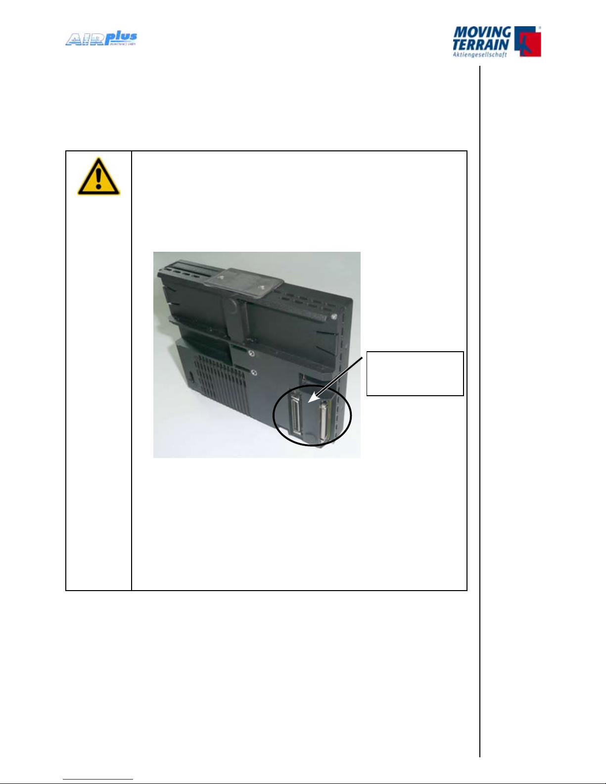
General Safety Precautions
CAUTION:
The two central connectors (50-pin MDR) of the MTVisionAir X ETSO are connected identically; strictly
avoid using both at the same time!
This could cause severe damage of the device.
Never disconnect the conducting connector during operation.
This could cause severe damage of the device.
Never store the device into the transport case when
equipped with battery packs.
This could cause overheating.
Always take care to allow sufcient ventilation of the
device when mounted.
Otherwise overheating could occur.
•
•
•
•
Always connect
ONLY ONE of
these connectors.

MTUX/IA-63-00 – Installation Manual
12 Date: 2017/02/17
INTENTIONALLY LEFT BLANK
MTUX/IA-63-00 – Installation Manual
13Date: 2017/02/1700
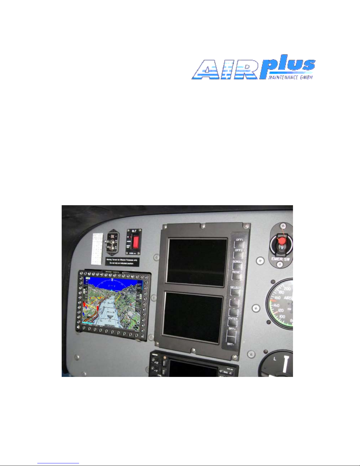
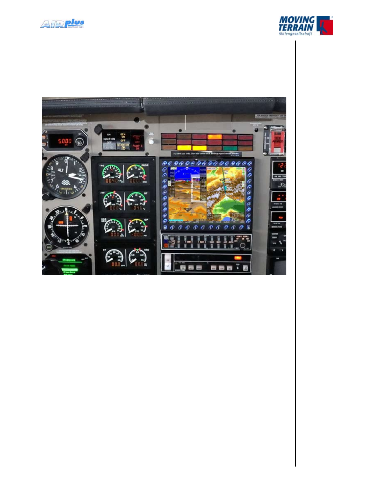
1. General information for Operating a MT-VisionAir X ETSO
MT-VisionAir X ETSO was designed to be installed and operated as a panel
mounted device, but can easily be removed for ight planning.
MT-VisionAir X ETSO is equally suited as a hand-held device.
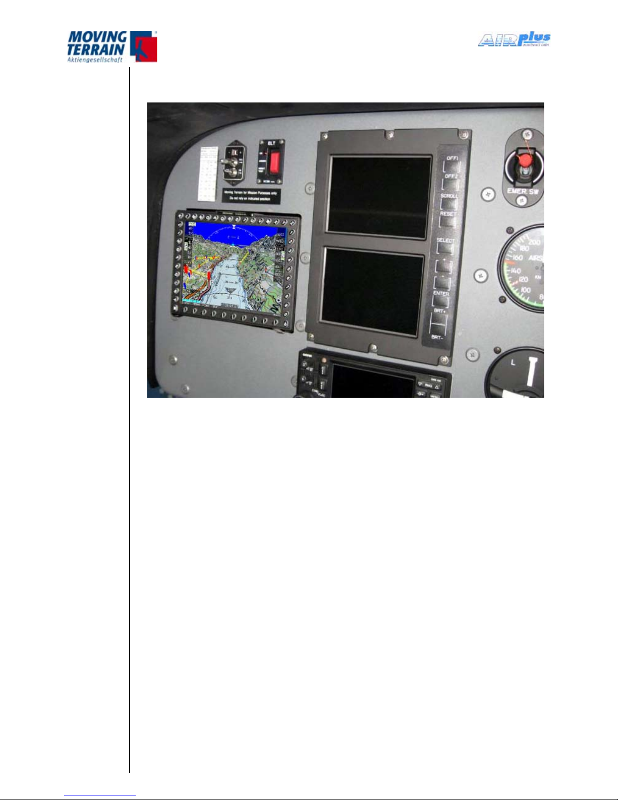
Fig. 1.1: MT-VisionAir X ETSO Panel mount installation in Piper JetProp
The Easy mount is permanently installed in the panel. The MT-VisionAir X
ETSO slides into the Easy mount, but can easily be removed for ight planning,
updates of the navigation data or charts, etc.
InstallationofthetheMT-VisionAirXETSOhasvirtuallynoinuence
on the weight and balance calculation.
Following installation, an EMI test has to be performed in the aircraft. Prior
to the rst ight it is mandatory to turn on the system and check cockpit
instruments for deviations from normal performance.
MTUX/IA-63-00 – Installation Manual
14 Date: 2017/02/17
2. Introduction of MT-VisionAir X ETSO
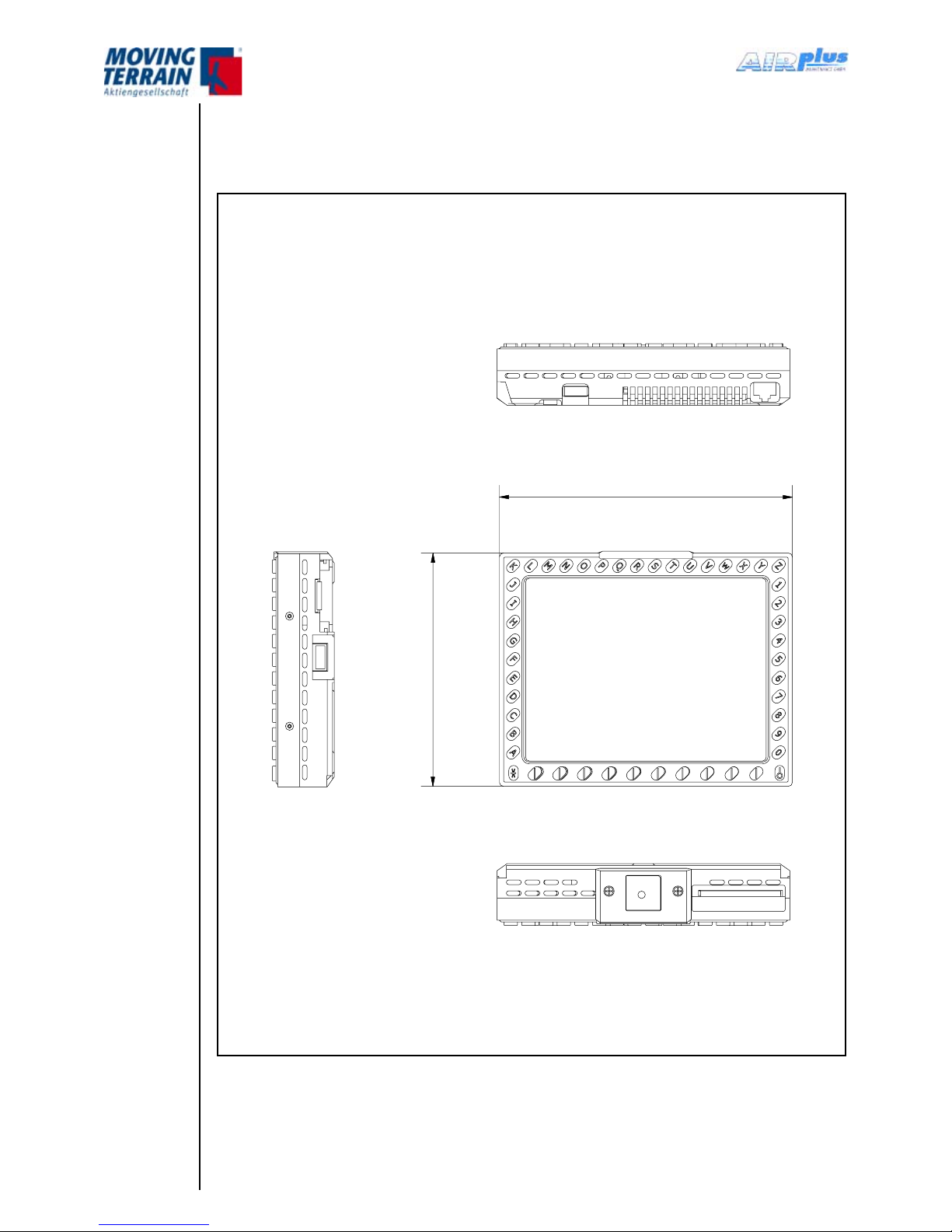
2.1 Views of device
157
1
2
5
Fig. 2: Views of MT-VisionAir X ETSO (1)
Bottom view
Front view
Top view
Right side view
157 mm
126 mm
MTUX/IA-63-00 – Installation Manual
15Date: 2017/02/1700
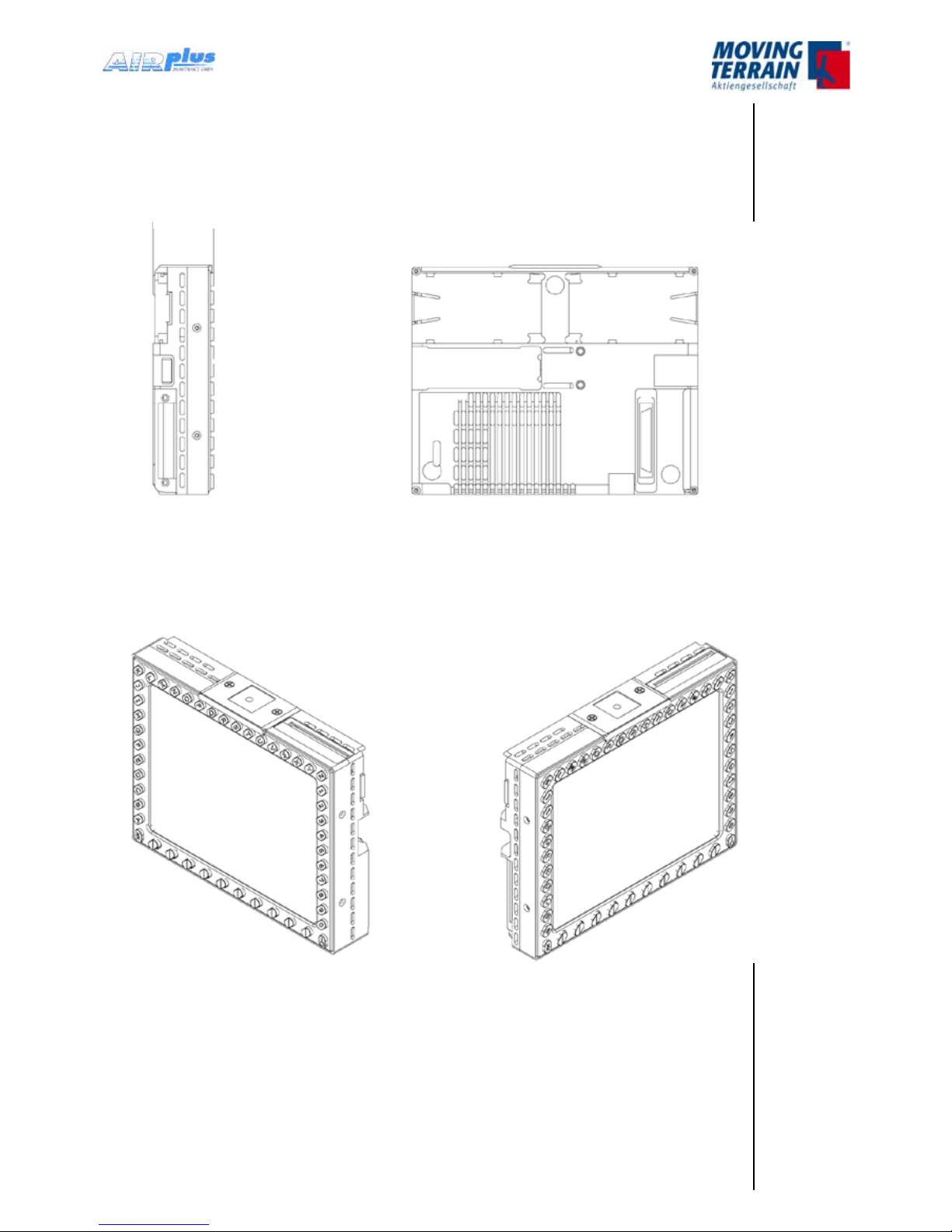
Left side view Rear view
33.1 mm
Fig. 2: Views of MT-VisionAir X ETSO (2)
MTUX/IA-63-00 – Installation Manual
16
Date: 2017/02/17
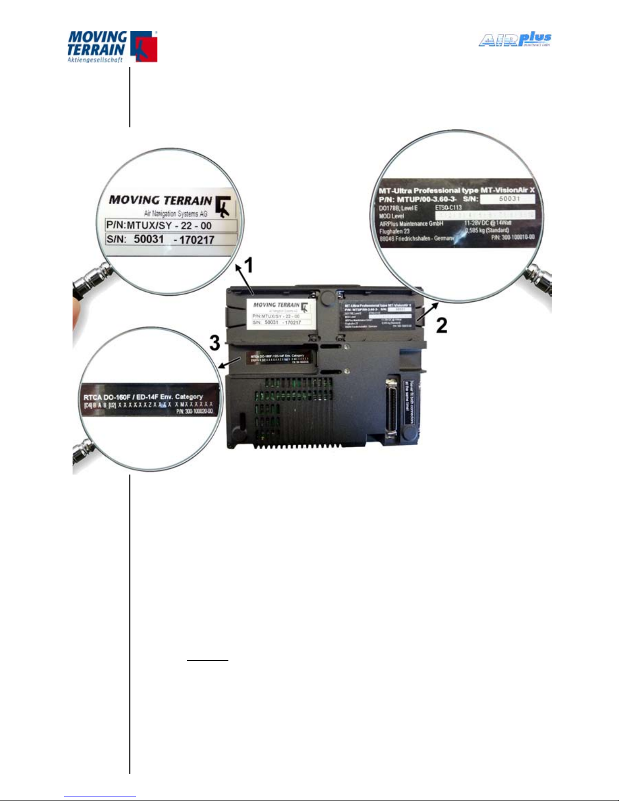
2.2 LabelDenition&SerialNumber
MT-VisionAir X ETSO units are marked with adhesive labels as shown:
1. MTIdenticationlabel -> example (not part of the ETSO approval)
P/N: MTUX/SY-22-00
S/N: 50031 - 170217
2. ETSO Part label
P/N: MTUP/00-3.60-3
S/N: 50031 (example)
(label P/N 300-100010-00)
Serial numbering system
S/N: XXXXX
3. Environmental Category Label
RTCA DO-160F / ED-14F Env. Category
[C4] B A B [U2] X X X X X X Z X X X X X M X X X X X X
(label P/N 300-100020-00)
MTUX/IA-63-00 – Installation Manual
17Date: 2017/02/1700
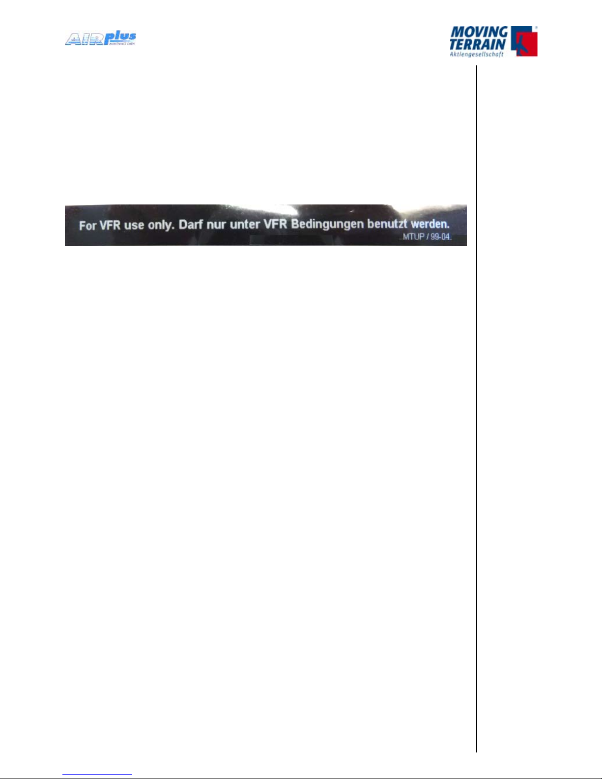
2.3 Warning Sign for Cockpit
This warning sign is included with every MT-VsionAir X ETSO device
and must be displayed in a clearly visible position in the cockpit next to
the MT-VisionAir X.
(label P/N MTUP/99-04)
The warning sign dimension is 100mm x 10mm.
MTUX/IA-63-00 – Installation Manual
18
Date: 2017/02/17
3. Installation of MT-VisionAir X ETSO
3.1 Installation of Easy mount in the cockpit panel
For installation of the MT-VisionAir X ETSO an Easy mount is used.
Choose the installation location according to requirement of application or
preferences:
in the cockpit panel
in other locations, e.g. the yoke.
3.1.1 Choosing the best location
The MT-VisionAir X ETSO should be easily visible during ight.
Choose the optimum readability angle.
Refer to the following gures showing the dimensions of the Easy mount
(without and with MT-VisionAir X ETSO) before specifying the location of
the panel cutout.
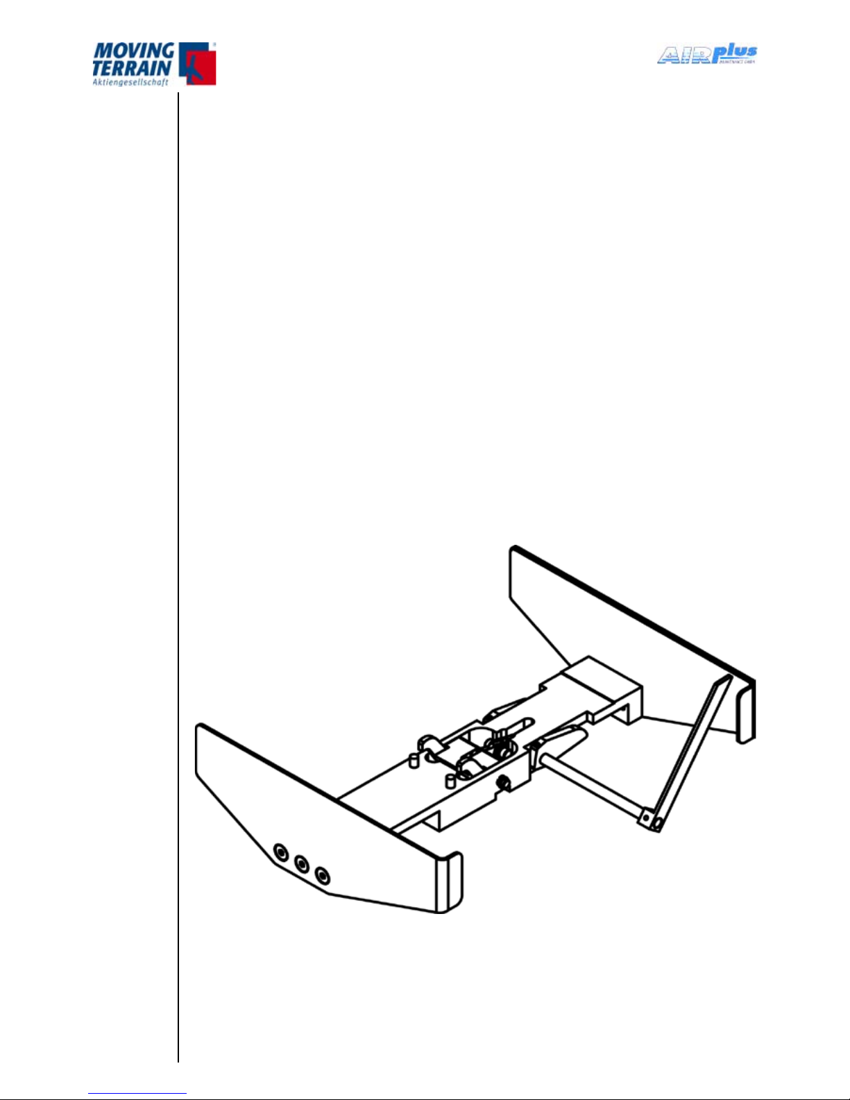
3.1.2 Easy mount sketch
Fig. 3.1.2: Easy mount sketch
•
•
•
•
•
MTUX/IA-63-00 – Installation Manual
19Date: 2017/02/1700
3.1.3 Panel cutout
The Easy mount must be rmly attached to the cockpit panel with screws.
Please use countersunk screws or rivets for installation in the instrument
panel (or onto the angled rail) as space of 158 mm including any protruding
screwheads must remain available for the device.
Panel cutout dimensions:
Width: 157.5 mm minimum (with latches in the rack), 160.5 mm optimum
Height: 128 mm
Depth: 46 mm
(all dimensions incl. 0.5 mm tolerance)
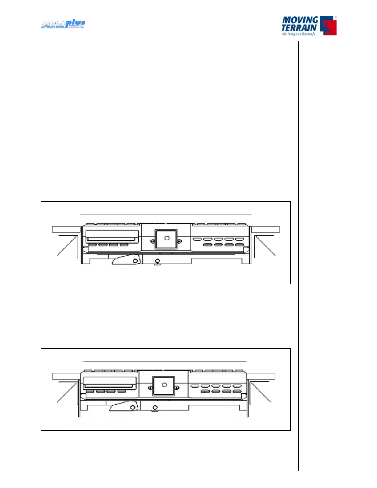
1. Installation for panel clearance of 160.5 mm
Mounting ush with cockpit panel or tilted mounting due to improved readability
angle (e.g. for mounting at co-pilots side).
Fig. 3.1.3 (1): Panel clearance 160.5 mm
2. Installation for panel clearance of 158 mm
Mounting at the rear side of the panel: to ush the unit with the panel relocate
the screws in the side mounting brackets.
Fig. 3.1.3.(2): Panel clearance 158 mm
157.5 mm
Panel
Angle
bracket for
mounting
Panel
Angle
bracket for
mounting
160.5 mm
Panel
Angle
bracket for
mounting
Panel
Angle
bracket for
mounting
MTUX/IA-63-00 – Installation Manual
20
Date: 2017/02/17
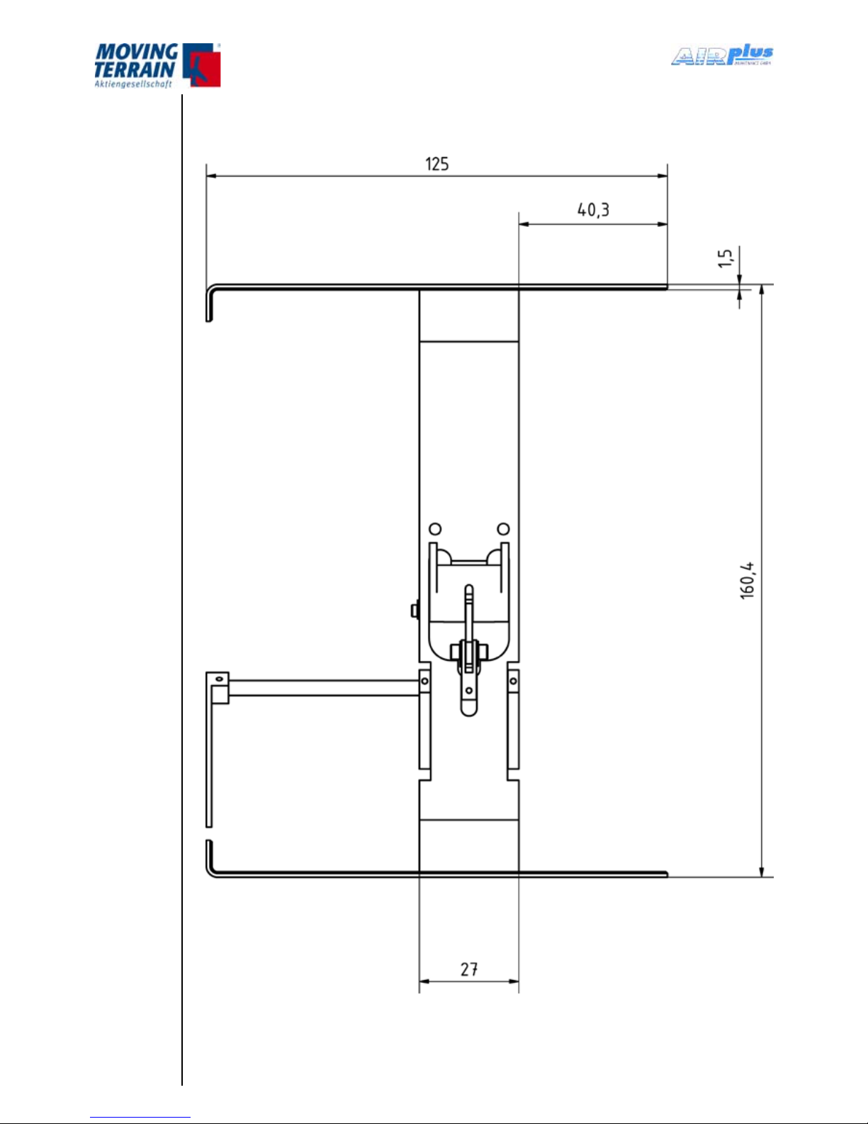
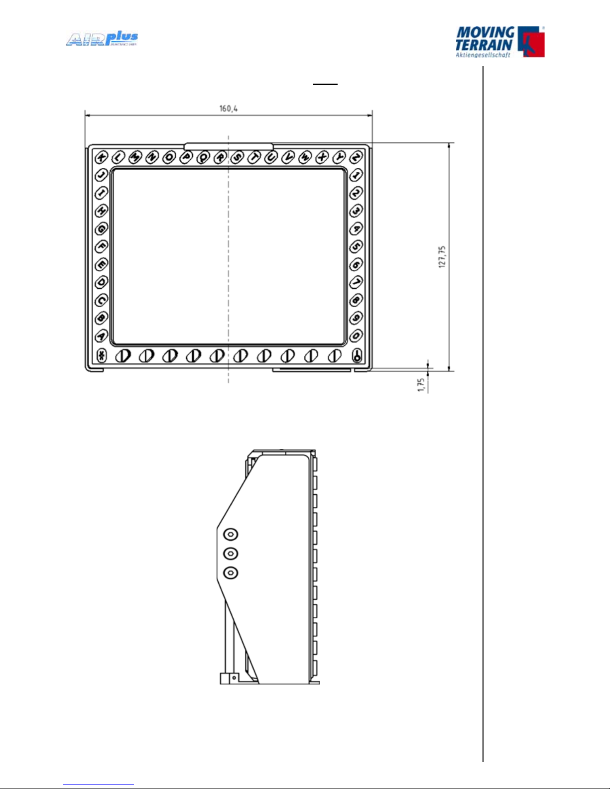
3.2.4 Dimensions of Easy mount
Fig. 3.1.4 (1): Front view of Easy mount / dimensions in mm
MTUX/IA-63-00 – Installation Manual
21Date: 2017/02/1700
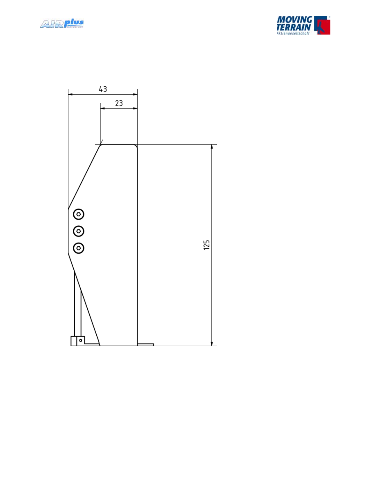
Fig. 3.1.4 (2): Side view of Easy mount / dimensions in mm
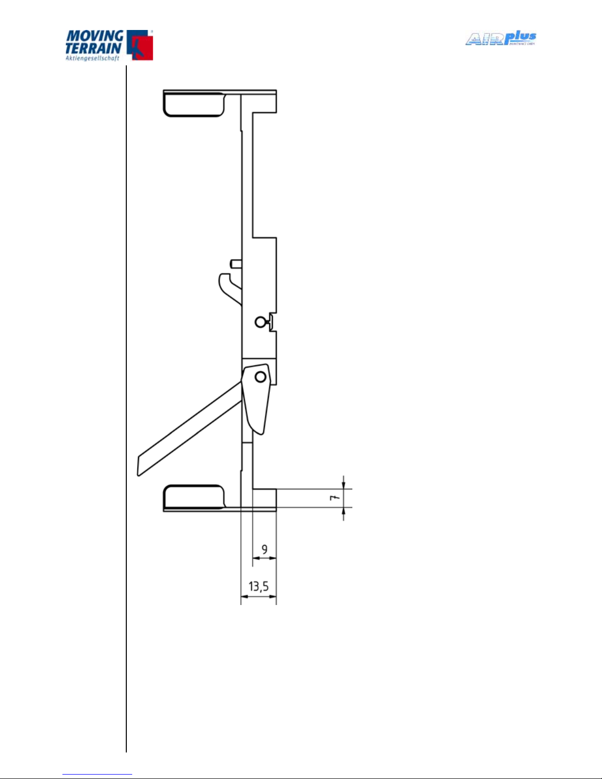
MTUX/IA-63-00 – Installation Manual
22
Date: 2017/02/17
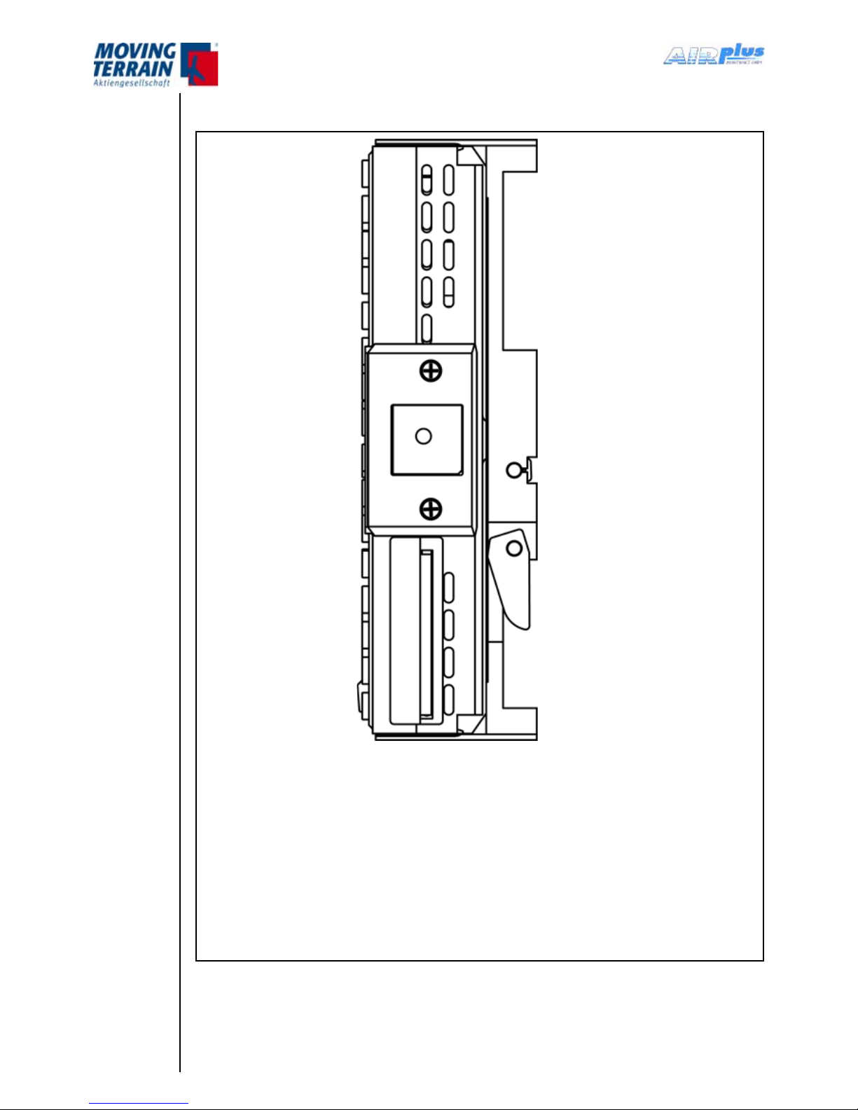
Fig. 3.1.4. (3): Top view of Easy mount / dimensions in mm
MTUX/IA-63-00 – Installation Manual
23Date: 2017/02/1700
3.1.5 Dimensions of MT-VisionAir X ETSO with Easy mount
Fig. 3.1.5 (1): Front view of MT-VisionAir X ETSO with Easy moun / dimensions in mm
t
Fig. 3.1.5. (2):
Side view of MT-VisionAir X ETSO with Easy mount
MTUX/IA-63-00 – Installation Manual
24
Date: 2017/02/17
Fig. 3.1.4. (3): Top view of MT-VisionAir X ETSO with Easy mount
MTUX/IA-63-00 – Installation Manual
25Date: 2017/02/1700
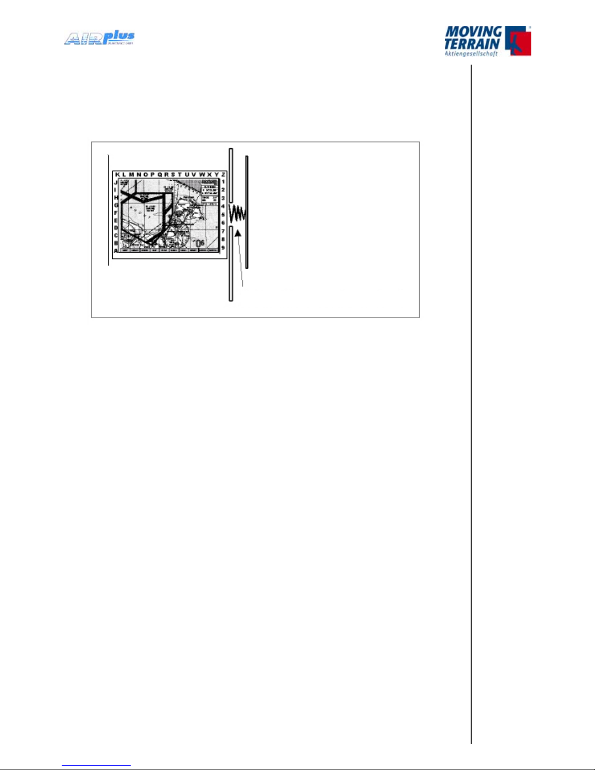
3.1.6 Remarks regarding installation
The device can be adversely affected if it is allowed to vibrate against xed
parts of the aircraft - see the symbolic sketch below.
Fig. 3.1.6: Observe to avoid adverse effects
The locking mechanism of the Easy mount must be easy to operate.
Leave a loop of the cable and bundle the cables so that the device can be
easily removed again.
spring action: very adverse effect
MTUX/IA-63-00 – Installation Manual 26 Date: 2017/02/17
3.1.7 View of an installation in a cockpit
Fig. 3.1.7: Installation in a cockpit EC 120
3.1.8 Removal and Insertion of the Device
Removal is required for several reasons:
Changing/charging of battery packs
Flight preparation can be performed outside of the cockpit.
Updates via USB device .
The manufacturer recommends that pilots make themselves familiar with
the removal and insertion of the device together with the facility providing
installation service and to pay attention to the correct installation method of
the Easy mount.
Please refer to the video instruction on the website of Moving Terrain (www.
moving-terrain.de) for a demonstration of how to insert and to remove the
MT-VisionAir X ETSO into/from the Easy mount.
•
•
•

MTUX/IA-63-00 – Installation Manual
27Date: 2017/02/1700
3.2 Installation of the Easy mount in other locations
For installation of the Easy mount in other locations (e.g. the yoke) special
mounting devices of other manufacturers may be suitable or required.
Please contact the customer’s service at Moving Terrain for detailed
information.

MTUX/IA-63-00 – Installation Manual 28 Date: 2017/02/17
INTENTIONALLY LEFT BLANK

MTUX/IA-63-00 – Installation Manual
29Date: 2017/02/1700
4. Installation of GPS
MT-VisionAir X ETSO is by default equipped with a Fast Integral GPS (with
integrated antenna).
For the conguration of the correct GPS in the software refer to chapter “
Connections”.
4.1 Installation of Fast Integral GPS
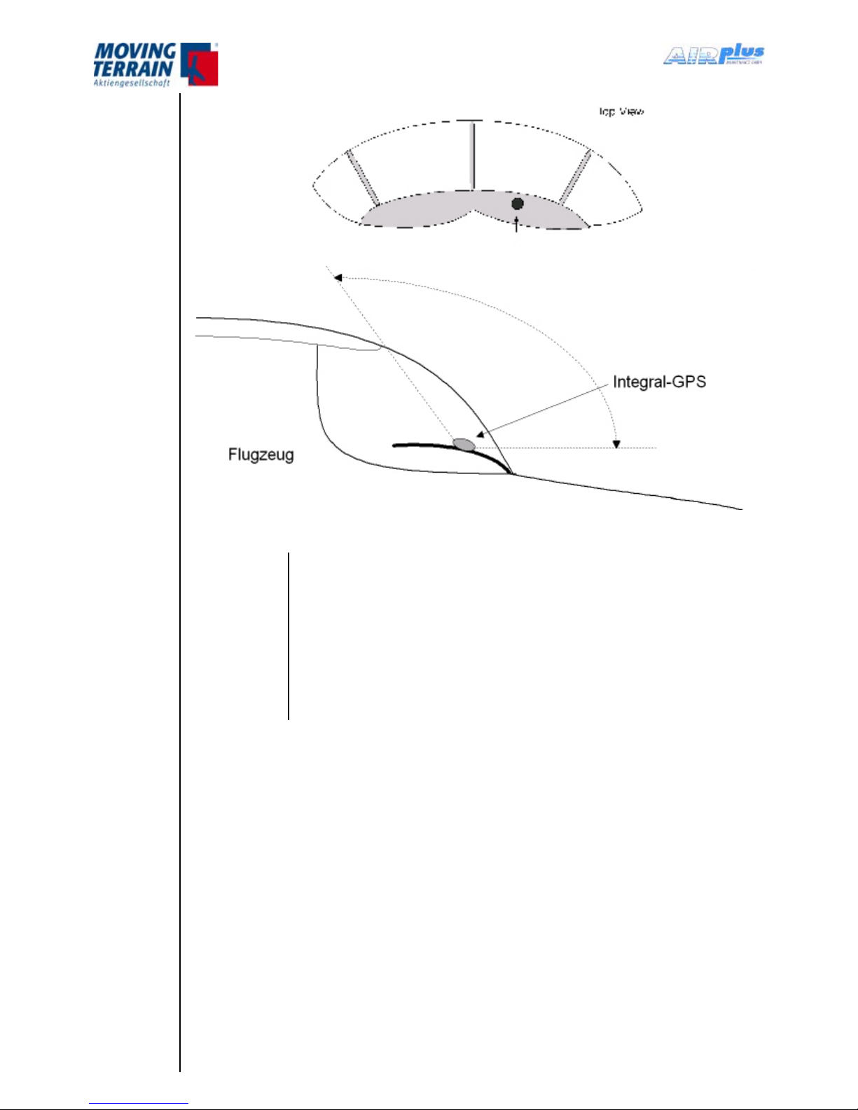
4.1.1 Recommended installation location of the Fast Integral GPS
The manufacturer recommends installation of the Fast Integral GPS on the
glare shield.
A windshield heater usually attenuates the incoming signal to such an
extent that placing the antenna under it does not make sense.
A segment of the sky as large as possible must be visible for the antenna
(integrated in the GPS!). The cable length is limited to 20 m.
Because of the high peaks of the digital signal a well shielded cable is
recommended to prevent interference with other units.
For the installation a ground plate (min 20x20 cm) made of conducting
material is recommended. Provide ground connection to aircraft structure. On
this ground plate the antenna is mounted with upward vision. Conducting
material (e.g. galvanized sheet metal) improves the reception.
•
•
•
•
MTUX/IA-63-00 – Installation Manual 30 Date: 2017/02/17
Fig. 4.1.1: Installation of the Fast Integral GPS on the glare shield
NOTES
For a glare shield made of plastics, installation beneath the
glare shield is also possible.
In this case observe to install the Fast Integral GPS top side
up.
The Fast Integral GPS can also be mounted on the outside of
the aircraft. In general a temperature limit of –20 °C must be
observed.
 Loading...