

Page 1
SECCIÓN EN ESPAÑOL
SECTION EN FRANÇAIS
AVAILABLE AT WWW.MOVINCOOL.COM
Page 2

Page 3

Page 4
Foreword
Congratulations on purchasing the MovinCool portable air conditioner.
This manual explains how to install and operate the MovinCool PC 7
portable air conditioning unit. Please read this operation manual
thoroughly to familiarize yourself with the features of the unit
and to ensure years of reliable operation. You may also find it
useful to keep this operation manual on hand for reference.
Attention:
(1) This unit is not intended for use by young children without supervision.
(2) The plug shall be accessible after installing the unit.
(3) The unit shall be installed in accordance with national wiring regulation.
(4) If the power cord is damaged, it must be replaced by the manufacturer or
a qualified technician. Contact your reseller for more information.
(5) Please wait 3 minutes before restarting the unit.
(6) Do not sit or stand on the unit.
(7) The proper electrical outlet for MovinCool unit must be equipped with a UL
approved ground fault breaker to prevent electrical shock from the unit.
(8) The minimum clearance from the unit to combustible surface: 3 feet (1.0 m)
(9) The AC outlet (115VAC, Single Phase, 60Hz) must be rated at 15A or higher.
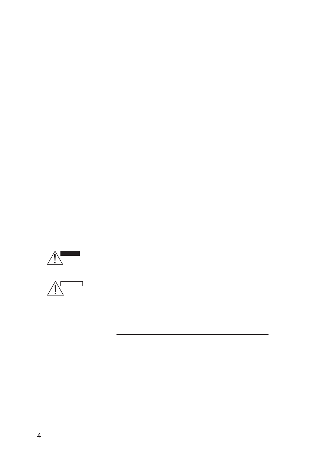
WARNING
CAUTION
This symbol refers to a hazard or unsafe practice which can result
in severe personal injury or death.
This symbol refers to a hazard or unsafe practice which can result
in personal injury or product or property damage.
Contents
Introduction 5
Unit description and function 6
Operation and indicators or remote control 8
Use of control panel 10
Water drainage methods 11
Maintenance/service 12
Safety cautions 13
Troubleshooting 14
Installation 15
LCDI Power Cord 20
Warranty 21
Page 5

INTRODUCTION
Mobile Air Conditioner
The PC7 is a small unit, which can adjust the temperature and humidity in a room
making it easy to use in different occasions.
It also has multiple functions, included Cooling, Dehumidifying, and Fan Modes.
This unit was designed especially to be used in a family house, office, etc. It has a compact
design compared to others with the same coolig capacity. Power consumption is low and the
noise is especially low.
Other air conditioning solutions are recommended when the ambient temperature is either
below 63 °F (17°C) or above 88° F (31°C).
Note: When the ambient temperature is high, condensation may occur to the unit.
ATTENTION
Before you use your PC7 air conditioner, please read this operation manual carefully so
that you get the best from the unit.
This operation manual is used for guidance and does not form part of a contract. We reserve
the right to make technical changes without prior notice.
CAUTION
There might be some water remained in the bottom of the condensate pan, push the PC7
gently and carefully to prevent water splashing out. Empty the water when moving the unit.
Page 6
UNIT DESCRIPTION AND FUNCTION
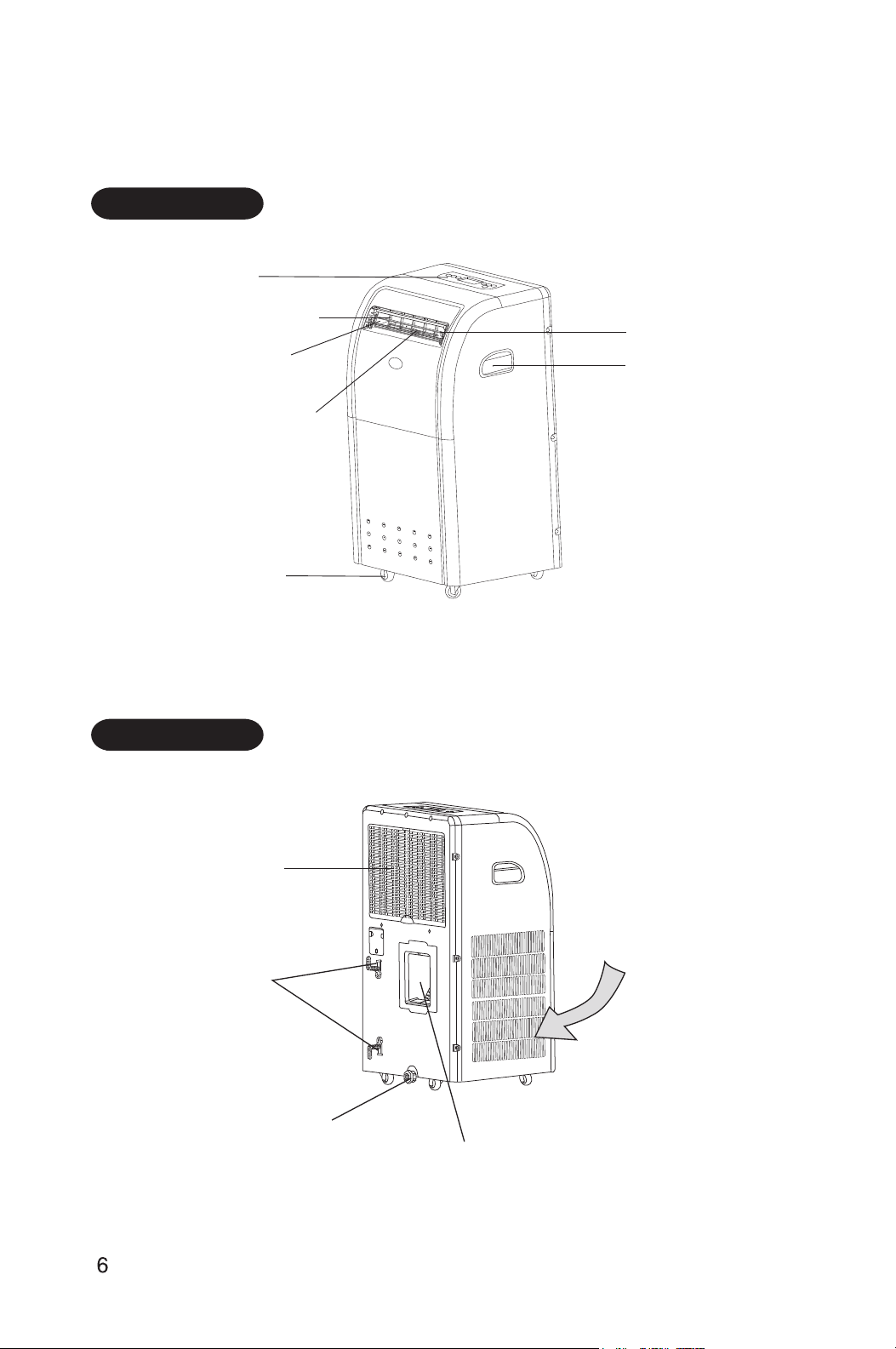
FRONT
Control panel
Left/right air swinging fins
Air outlet
Left/right air direction
control tab
Caster
Up/down air louver
Handle
Note: Open the up/down air louver to the highest position before the unit is turned on.
BACK
Air-return grill
Air inlet
Power cord holders
Base stopper
Exhaust air outlet
Page 7
UNIT DESCRIPTION AND FUNCTION (cont.)
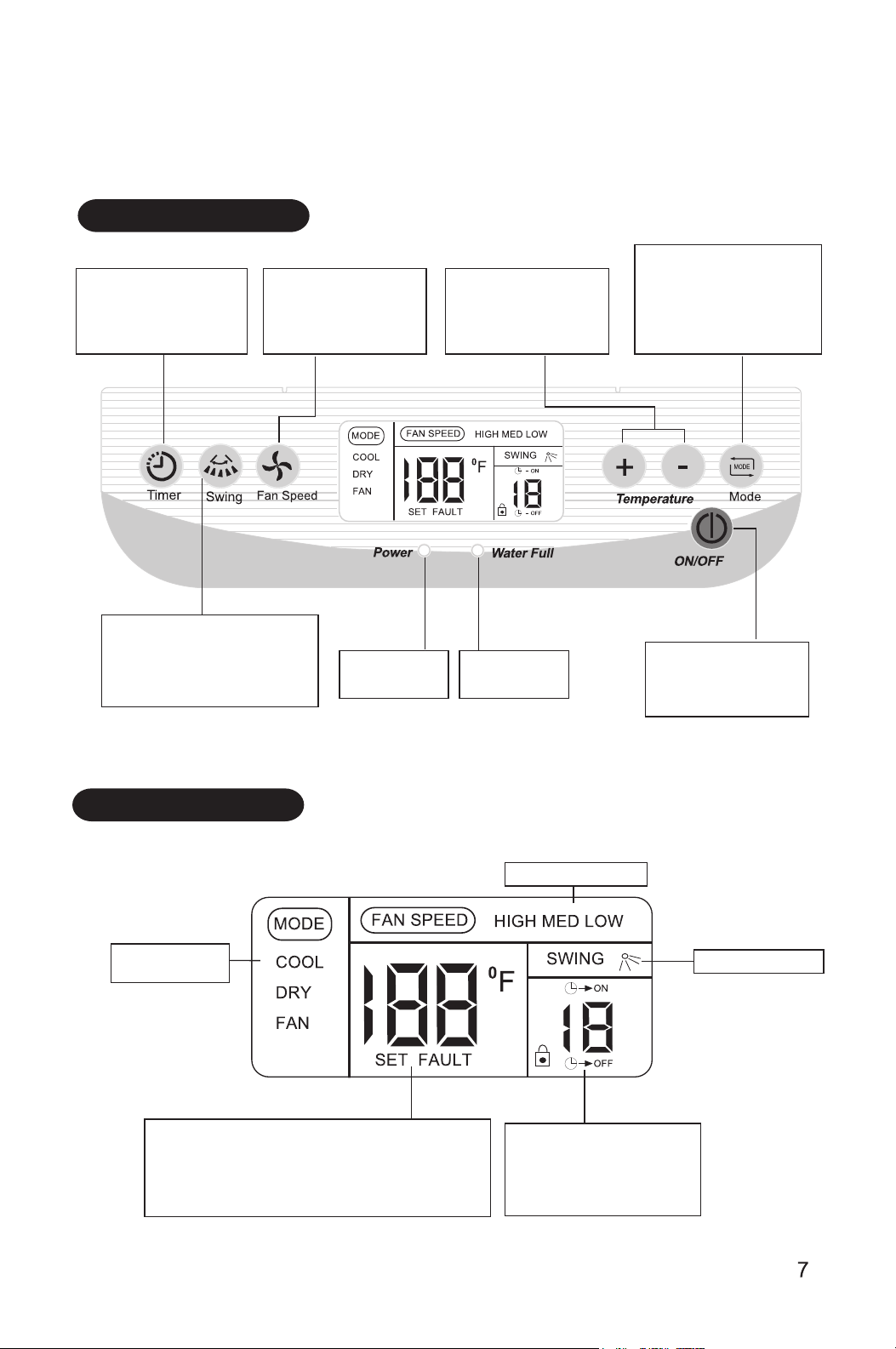
CONTROL PANEL
TIMER Button
Press this button to set the
time for switch-on, switch-off
timer or to delete the timer.
SWING Button
Press this button to
activate/deactivate
auto-swing feature.
FAN SPEED Button
Press this button to
choose high, medium or
low speed of air delivery.
POWER
Indication lamp
TEMP Button
Press these buttons to
change the set point
temperature.
WATER FULL
indication lamp
MODE Button
Press this button to select
the modes of cooling,
dry or fan mode.
ON/OFF Button
Press this button to turn
the unit ON or OFF.
DISPLAY SCREEN
Operation mode
indicator
Display of preset temperature and failure code
when SET is displayed, the displayed digits indicate
the preset temperature.
When FAULT is displayed, the displayed digits
indicate the code of failures.
Fan speed indicator
Swinging indicator
Display of time setting
The displayed digits indicate
the remaining time of
on/off operation.
Page 8

OPERATON AND INDICATORS OF REMOTE CONTROL
Remote Control
Install the supplied batteries (type AAA 1.5V) to the remote controller.
Set temperature indicator
Cooling indicator
Drying indicator
Fan Mode indicator
Timer time or present time indicator
MODE button
This button is used to select the cooling,
drying,fanning mode of operation.
This button is used to set the switch-on or
switch-off time. Use together with the “HOUR”
button, the time setting can be made within
the range of 00-23 hours, with the interval of
one hour.
Press this button to choose high, medium
or low-speed of air delivey.
TIMER button
FAN SPEED button
Not Used.
Fan speed indicator
Lock key indicator
Air flow indicator
Temperature setting button
Each presing of the button, the
temperature setting is increased or
decreased by 1°F.
ON/OFF button
Press this button to turn the unit ON or OFF.
This button is used to set the timer time or the
present time.
This button is used to set the present time.
Press this button to select the swinging or
fixed air delivery.
HOUR button
MIN button
SWING button
HOLD button
Press this button to lock or unlock the keyboard.
Page 9

OPERATION AND INDICATORS OF REMOTE CONTROL (cont.)
Present Time Setting Procedure
When batteries are inserted,time is automatically set to 00:00. Set the present time as
follows.
Example:Set time to 10:30
Continuously press the HOUR button for
2 seconds .
The time indicator is blinking and can set the HOUR time.
Press the HOUR button. (Set to 10 :)
Continuously press the MIN button for 2
seconds .
The time indicator is blinking and can set the MIN time.
Press the MIN button. (Set to 30)
Press the ON/OFF button to confirm the set time
or it automatically exits the time setting state after
15 seconds.
If the remote control is at abnormal state, take out the batteries under the back cover
to clear off the display.
NOTE : The timer is set based on the present time.So set the present time correctly.
Page 10

USE OF CONTROL PANEL
Dehumidifying and Cooling Operation
The operating ranges for cooling operation and dehumidifying are 63ºF-88ºF(17ºC-31ºC).
Power Source
WARNING
The AC outlet (115 VAC,Single Phase,60Hz) must be rated at 15A or higher.
The AC socket must be firm and reliable.
Do not connect the unit to a multiple socket outlet which is also being used for other
electrical appliances.
Insert the AC power plug securely into the AC socket before using the unit, when it beeps
after 2 seconds, press ON/OFF button, the unit begins to operate.
Cooling Operation
1.Repeatedly press MODE button to choose the cooling mode, LCD window shows"COOL".
2.Repeatedly press TEMP+or TEMP-button to set a proper room temperature at 63ºF-88ºF
(17ºC-31ºC).
3. Press FAN SPEED button to choose a proper fan speed: high, medium, low speed.
4. Press SWING button to adjust the air delivery direction, the LCD window shows"
Note:
In order to improve the cooling efficiency of the unit:
a) Do not place the unit in direct sunlight.
b) Do not place the unit in near other heat source.
c) The set temperature can be set at 63ºF(17ºC) or higher, however the unit operates
intermittently at less than 70ºF (21ºC).
Dehumidifying Operation
1. Keep the windows and the doors closed to effectively dehumidify the room.
2. Repeatedly press MODE button to choose the dehumidifying mode, the LCD window
shows "DRY", and fan speed can not be adjusted.
Page 11

USE OF CONTROL PANEL (cont.)
Timer Set Function
To set time to start the unit with the unit off (stand by power), press Timer button, the LCD
window
like. The setting range is 1-12 hours.
To set time to stop the unit with the unit operating, press TIMER button, the LCD window
shows"
", repeatedly press the HOUR button, set the time to stop the unit as you
like. The setting range is 1-12 hours.
Note: If cancel the timer setting, press TIMER button again.
Auto Swing Function
1. Press" " button, LCD window shows" " and the louvers swing automatically.
2. Press once again" " button, the symbol " " and the LCD window disappears,
and the louvers stop swinging automatically.
Attention:
Press TEMP+ and Temp-buttons together for more than 2 seconds to lock the keys, the
LCD window shows " ".Press the two buttons again to unlock the keys, the symbol " "
disappears.
shows" , repeatedly press the HOUR button, set the time to start as you
Water Drainage Methods
When the unit is on cooling operation, the unit drains the water by RECYCLE PUMP.
When the water in the condensate pan is on Low water level, the RECYCLE PUMP
does not operate, and the unit runs normally at setting mode.
When the water in the condensate pan stays on Normal water level for 3 minutes, the
RECYCLE PUMP operates,and the unit runs normally at setting mode.
When the water in the condensate pan stays on High water level for 1 minute, the
compressor stops, and the RECYCLE PUMP continues to operate. Indoor and outdoor
fan motors run as previous state.
When the water in the condensate pan stays on High water level for 40 minutes , the
unit tums off, and WATER FULL lamp illuninates,LCD window indicates failure code E5.
At this time, open the base stopper on the bottom of the unit, and put the water tray
under the base to drain the excessive water (shown as below Fig.). Put the base stopper
back and tighten to prevent water flashing out .
NOTE: If there is much water condensed in the condensate pan, empty the water in the
water tray several times before it becomes full.
Page 12

MAINTENANCE/SERVICE
Pull the power plug out of the socket before cleaning.
Make sure there is no power to the unit before maintenance or repair to
prevent accident caused by electrical shock.
CLEANING OF AIR FILTER
If the air filter is blocked with a lot of dust, the air flow volume will reduce. Clean the air
filter once every two weeks.
Open and clean the air filter
1. Directly grasp the hook on the rear side to remove the air-return grill.
2. Take out the air filter from the filter cover.
3. Wash the air filter by immersing it gently in warm (about 104°F/40°C) water with a
neutral detergent.
4. Rinse the filter of detergent and dry it thoroughly in a shaded place.
5. Install the air filter back to its original place.
CLEANING OF AIR CONDITIONER
Clean the surface of the unit with a damp cloth, then dry using a duster or similar.
Do not use chemical solvent (benzene, alcohol, glaze, etc.) to clean the
surface of the unit.
If you do so, the surface may be scratched, damaged, and the whole casing
may become deformed.
PRIOR TO OPERATIONAL SEASONS
1. Check the air inlets and outlets of the unit are not blocked.
2. Make sure that air filter is properly in place before operating the unit. If the unit is
operated with air filter removed, dust and foreign objects may result in faulty
performance of the air conditioner.
3. Put the base stopper back to the rear of the unit and tighten it.
Page 13

MAINTENANCE/SERVICE (cont.)
AFTER OPERATIONAL SEASONS
1. Turn off the unit, and disconnet the power source.
2. Make proper maintenance to the air filter and other parts.
3. Open the base stopper to drain out the condensed water in the condensate pan, then
operate the unit in fan mode for half a day to let the condensate pan dry.
4. Put the base stopper back and tighten it.
5. Use plastic sheet to cover the unit to prevent dust or filth from entering the unit.
Base stopper
SAFETY CAUTIONS
OCCASION
Do not use the unit in a very narrow room with obstacles to avoid damage to the unit.
Do not use the unit in direct sunlight to avoid surface color changing.
Do not use the unit in water or near water to avoid leakage of electricity.
Do not use the unit near gas appliances, fires or in the vicinity of flammable liquids.
POWER SOURCES
Do not use a damaged or improper AC socket.
When unplugging the unit, hold the power plug securely and pull it out carefully.
Do not use an extension cord.
OTHERS
Keep the unit 3 feet (1.0 m) away from TV sets or radios to avoid the risk of
electromagnetic interference.
Do not use the unit with the air outlet close to walls or cover the air outlet to avoid
overheating.
SERIOUS CAUTION
Do not topple over or incline the unit. If the unit is toppled over, unplug the unit and
contact your MovinCool reseller or a qualified technician for advice.
Do not spray insecticide or other chemicals to the unit as the plastic case may be
deformed.
Page 14

TROUBLESHOOTING
Check the following items before calling your MovinCool reseller or a qualified technician.
Condition
Unit does not
operate at all.
Cooling efficiency
is not good.
Noise and vibration
The unti starts and
stops frequently.
Check Area Remedy
Is there power?
Is it plugged in?
Is the fuse or circuit breaker switch turned off?
Is SET TIME proper? Change SET TIME.
Are there batteries in the remote control?
Are the batteries run down?
Is air inlet or outlet blocked?
Is there any other heat source in room? Move the heat source.
Are air filters dirty?
Is SET TEMP. proper?
Is indoor fan speed set at low?
It is the inner liquid(refrigerant-geration)
flowing inside.
Is the unit leveled?
Is the voltage of the power source normal?
Is the exhaust air duct fixed improperly or
bended sharply?
Did you add exhaust air duct by yourself ?
Plug into the wall socket.
Change the fuse or turn switch on.
Install the supplied batteries.
Replace the batteries.
Clean air inlet or outlet.
Clean the air filters.
Set proper temperature.
Set proper speed.
It is normal.
Place it on a flat, level surface.
Keep the power source in rated
voltage.
Install the exhaust air duct properly.
See page 15 to 17.
Do not add exhaust air duct and
remove it by yourself.
In case of major malfunction, unplug the unit immediately and call for service.
The fuse and switch often break.
The power cord is hot or the sleeve of the cord is broken.
Something is abnormal.
Self-diagnosis function
-diagnostic codes are displayed on the control panel of the unit under the following
Self
conditons.
Failure code Diagnosis of malfunction
E2
E3
E4
E5
14
Room temperature sensor failure
Coils sensor failure
Units abnormality protection
Water level over the limits
Page 15

INSTALLATION
Selection of Installation Location
Put the unit on a flat location where the air outlets are not
covered up, place the unit no less than 20 inch (500 mm)
away from a wall or other obstacle.
1
Power cord holder installation
Install the supplied power cord holders with the supplied
two self-tapping screws to the unit.
Power cord holder
Exhaust Air Duct Mounting Method
Mounting through the window
1) Shrink the exhaust air duct.
2) Insert the duct into the square adapter.
Rotate the duct (2-3 rounds).
3) Insert the other end of the duct into the window exhaust adapter 1.
Rotate the duct (2-3 rounds). Attach the window exhaust adapter 2.
4) Fix the square end of the duct to the exhaust teminal of the unit.
5) Put the other end (discharge) to the nearest window. See page 18 for window
slider kit installation.
Note: The length of the exhaust air duct is between 24 in (600 mm)-72 in (1800 mm).
When installing, minimum length is recommended.
When mounting, keep the duct horizontal. Do not connect other duct to extend. This
can cause malfunction.
Square end of exhaust air duct
Exhaust air duct
Window
exhaust
adapter1
Window exhaust adapter2
Page 16

INSTALLATION (cont.)
Mounting through the wall
1) Shrink the exhaust air duct.
2) Insert the duct into the square adapter. Rotate the duct (2-3 rounds).
3) Insert the other end of the duct into the window exhaust adapter 1.
Rotate the duct (2-3 rounds). Attach the window exhaust adapter 2.
4) Fix the square end of the duct to the exhaust terminal of the unit.
Correct mounting is shown below. The height of the hole from the floor should be 16
inch (400mm) - 51 inch (1300 mm).
Page 17

INSTALLATION (cont.)
If the exhaust air duct requires bending, see figures below.
Incorrect duct mounting Fig. 4 (Bending the duct sharply can easily cause malfunction.)
Page 18

INSTALLATION (cont.)
Window Slider Kit Installation
The window slider kit is designed to fit most standard "vertical" and "horizontal" widow
applications.However, It may be necessary for you to improve/modify some aspects
of the installation procedures for certain types of windows. Please refer to Fig.5 &
Fig. 6 for minimum and maximum window openings.
Fig. 5 Horizontal window
Window slider kit
Minimum: 26-5/8" (675mm)
Maximum: 48-3/8" (1230 mm)
Fig. 6 Vertical window
Window slider kit
Minimum: 26-5/8" (675mm)
Maximum: 48-3/8" (1230 mm)
Install the Board I and II with the supplied screws,nuts and washers.
Board I
Board II
Nut
Washer
Washer
Spring Washer
Screw
Page 19

INSTALLATION (cont.)
Installation Accessories Fig. 7
Description
Exhaust air duct with adapters...........4/set
Stretches from 19-1/2" (500 mm) up to 78-3/4" (2000 mm)
Adjustable window slider kit.........................2/set
Stretches from 26-5/8" (675 mm) up to 48-3/8" (1230 mm)
Power cord holder......2/set
Screw.........................2 pcs
Self-tapping screw.....4 pcs (2 pcs are extra.)
Nut.............................2 pcs
Washer.......................4 pcs
Spring washer............2 pcs
Installation Accessories
Exhaust air duct
Square end of exhaust air duct
Fig. 7
Window exhaust adapter 1
Window exhaust adapter 2
Adjustable window slider kit
Page 20

LCDI POWER CORD
WARNING
The LCDI device is a non-serviceable part. Attempting to open the device may expose
the user to hazardous electric shock, and voids any warranties and performance claims.
Manufacturer’s liability is limited to the replacement of the device.
CAUTION
1. Read manual for proper use and handling of this device.
2. Press "RESET" button before starting the unit. Press "TEST" to check function then
"RESET" again. Start the unit.
3. Do not immerse in water.
4. This device must only be plugged into an appropriate wall outlet.
5. In the event that this device trips, the cause of the malfunction should be corrected
befote any further use.
6. Using the device beyond recommended voltage poses risk to users.
"RESET" button
"TEST" button
Page 21

DENSO SALES CALIFORNIA, INC.( “DENSO”) warrants its MOVINCOOL Products only to the
extent stated in its official written warranties. Unless otherwise specifically provided in writing by
DENSO, DENSO warrants to end-user that the Products shall be free of defects in materials or
workmanship and will function in accordance with DENSO’s published specifications under
ordinary intended use and service for a period of twelve(12) months after delivery to the enduser.
DENSO shall, at its sole option, repair or replace any defective Product covered by this warranty.
Such remedy shall be end-user’s sole remedy with respect to any particular defect in the Products.
This warranty does not cover defects or malfunctions which result from causes beyond DENSO’s
control, including, without limitation, ( )unusual physical or electrical stress;( ) accident, neglect,
abuse,misuse or other abnormal use;( ) failure to perform routine maintenance in accordance
with DENSO’s recommended procedures;(iv) normal wear and tear; (v) repairs or attempted
repairs by an unauthorized person;( )modifications or alterations to the Products;( )use with
supplies or devices not supplied or approved by DENSO; or( )improper installation or service.
This warranty shall extend only to the original end-user and shall be void if any labels or other
identifying marks permanently affixed to Products when shipped by DENSO are removed,
altered, defaced or obliterated.
The aforesaid warranty is the only warranty made by DENSO with respect to the Products and
is in lieu of all obligations or liabilities on the part of DENSO for damages arising out of or in
connection with the sale, use or performance of the Products, including, without limitation, any
lost profits or any other consequential, incidental, special or exemplary damages of any kind.
DENSO DISCLAIMS ALL OTHER WARRANTIES WITH REGARD TO THE PRODUCTS,
INCLUDING ALL IMPLIED WARRANTIES OF MERCHANTABILITY AND FITNESS FOR USE.
THERE ARE NO WARRANTIES WHICH EXTEND BEYOND THE DESCRIPTION
CONTAINED HEREIN.
PURCHASE DATE:
SERIAL NUMBER:
Page 22

DENSO SALES CALIFORNIA, INC.
Long Beach CA,90810
www.movincool.com
P/N: 484007- 3290EN First lssue: March 2010
 Loading...