

MovinCool Office Pro 63 Service Manual
SERVICE MANUAL
OFFICE PRO 63
SERIAL NUMBER FROM JANUARY 2008 (0108) TO PRESENT
DocID: 00G00017E

© 2008 DENSO SALES CALIFORNIA, INC.
All rights reserved. This book may not be reproduced or copied, in
whole or in part, without the written permission of the publisher . DENSO
SALES CALIFORNIA, INC. reserves the right to make changes without
prior notice. MovinCool is a registered trademark of DENSO
Corporation.

Table of Contents
Table of Contents
Operation Section
1. PRECAUTIONS FOR SAFETY
1.1 Foreword. . . . . . . . . . . . . . . . . . . . . . . . . . . . . . . . . . . . . . . . . . . . . . . . . . . . . . . . . . . . . . . . . . . . . . . 6
1.2 Definition of Terms . . . . . . . . . . . . . . . . . . . . . . . . . . . . . . . . . . . . . . . . . . . . . . . . . . . . . . . . . . . . . . . 6
1.3 General Precautions. . . . . . . . . . . . . . . . . . . . . . . . . . . . . . . . . . . . . . . . . . . . . . . . . . . . . . . . . . . . . . 6
2. GENERAL DESCRIPTION
2.1 Spot Cooler. . . . . . . . . . . . . . . . . . . . . . . . . . . . . . . . . . . . . . . . . . . . . . . . . . . . . . . . . . . . . . . . . . . . . 7
2.2 Compact Design. . . . . . . . . . . . . . . . . . . . . . . . . . . . . . . . . . . . . . . . . . . . . . . . . . . . . . . . . . . . . . . . . 7
2.3 Easy Transportation and Installation. . . . . . . . . . . . . . . . . . . . . . . . . . . . . . . . . . . . . . . . . . . . . . . . . . 7
2.4 Energy Conservation . . . . . . . . . . . . . . . . . . . . . . . . . . . . . . . . . . . . . . . . . . . . . . . . . . . . . . . . . . . . . 7
3. CONSTRUCTION
3.1 Exterior Dimensions . . . . . . . . . . . . . . . . . . . . . . . . . . . . . . . . . . . . . . . . . . . . . . . . . . . . . . . . . . . . . . 8
3.2 Exterior Components . . . . . . . . . . . . . . . . . . . . . . . . . . . . . . . . . . . . . . . . . . . . . . . . . . . . . . . . . . . . . 9
3.3 Internal Structure . . . . . . . . . . . . . . . . . . . . . . . . . . . . . . . . . . . . . . . . . . . . . . . . . . . . . . . . . . . . . . . 10
3.4 Basic Construction . . . . . . . . . . . . . . . . . . . . . . . . . . . . . . . . . . . . . . . . . . . . . . . . . . . . . . . . . . . . . . 10
3.5 Air Flow. . . . . . . . . . . . . . . . . . . . . . . . . . . . . . . . . . . . . . . . . . . . . . . . . . . . . . . . . . . . . . . . . . . . . . . 11
3.6 Electrical System . . . . . . . . . . . . . . . . . . . . . . . . . . . . . . . . . . . . . . . . . . . . . . . . . . . . . . . . . . . . . . . 11
3.7 Compressor and Fans . . . . . . . . . . . . . . . . . . . . . . . . . . . . . . . . . . . . . . . . . . . . . . . . . . . . . . . . . . . 11
3.8 Transformer . . . . . . . . . . . . . . . . . . . . . . . . . . . . . . . . . . . . . . . . . . . . . . . . . . . . . . . . . . . . . . . . . . . 11
3.9 Condensate Pump . . . . . . . . . . . . . . . . . . . . . . . . . . . . . . . . . . . . . . . . . . . . . . . . . . . . . . . . . . . . . . 12
3.10 Drain Tanks (optional). . . . . . . . . . . . . . . . . . . . . . . . . . . . . . . . . . . . . . . . . . . . . . . . . . . . . . . . . . . . 12
4. SPECIFICATIONS
4.1 Technical Specifications . . . . . . . . . . . . . . . . . . . . . . . . . . . . . . . . . . . . . . . . . . . . . . . . . . . . . . . . . . 13
4.2 Characteristics . . . . . . . . . . . . . . . . . . . . . . . . . . . . . . . . . . . . . . . . . . . . . . . . . . . . . . . . . . . . . . . . . 15
5. REFRIGERANT SYSTEM
5.1 Refrigerant System Construction . . . . . . . . . . . . . . . . . . . . . . . . . . . . . . . . . . . . . . . . . . . . . . . . . . . 16
5.2 Compressor . . . . . . . . . . . . . . . . . . . . . . . . . . . . . . . . . . . . . . . . . . . . . . . . . . . . . . . . . . . . . . . . . . . 17
5.3 Condenser . . . . . . . . . . . . . . . . . . . . . . . . . . . . . . . . . . . . . . . . . . . . . . . . . . . . . . . . . . . . . . . . . . . . 18
5.4 Capillary Tube. . . . . . . . . . . . . . . . . . . . . . . . . . . . . . . . . . . . . . . . . . . . . . . . . . . . . . . . . . . . . . . . . . 18
5.5 Evaporator . . . . . . . . . . . . . . . . . . . . . . . . . . . . . . . . . . . . . . . . . . . . . . . . . . . . . . . . . . . . . . . . . . . . 18
5.6 High Pressure Switch . . . . . . . . . . . . . . . . . . . . . . . . . . . . . . . . . . . . . . . . . . . . . . . . . . . . . . . . . . . . 18

Table of Contents
6. ELECTRICAL SYSTEM
6.1 Circuit Diagram and Control Box . . . . . . . . . . . . . . . . . . . . . . . . . . . . . . . . . . . . . . . . . . . . . . . . . . . 19
6.2 Basic Operation of The Office Pro 63 Electrical Circuit . . . . . . . . . . . . . . . . . . . . . . . . . . . . . . . . . . 20
6.3 Transformer . . . . . . . . . . . . . . . . . . . . . . . . . . . . . . . . . . . . . . . . . . . . . . . . . . . . . . . . . . . . . . . . . . . 22
6.4 Control Box. . . . . . . . . . . . . . . . . . . . . . . . . . . . . . . . . . . . . . . . . . . . . . . . . . . . . . . . . . . . . . . . . . . . 23
6.5 Fan Motor . . . . . . . . . . . . . . . . . . . . . . . . . . . . . . . . . . . . . . . . . . . . . . . . . . . . . . . . . . . . . . . . . . . . . 25
6.6 Compressor Motor . . . . . . . . . . . . . . . . . . . . . . . . . . . . . . . . . . . . . . . . . . . . . . . . . . . . . . . . . . . . . . 26
6.7 Condensate Pump . . . . . . . . . . . . . . . . . . . . . . . . . . . . . . . . . . . . . . . . . . . . . . . . . . . . . . . . . . . . . . 27
6.8 Drain Switch . . . . . . . . . . . . . . . . . . . . . . . . . . . . . . . . . . . . . . . . . . . . . . . . . . . . . . . . . . . . . . . . . . . 29
6.9 Automatic Restart after Power Interruption. . . . . . . . . . . . . . . . . . . . . . . . . . . . . . . . . . . . . . . . . . . . 30
6.10 Compressor Protection. . . . . . . . . . . . . . . . . . . . . . . . . . . . . . . . . . . . . . . . . . . . . . . . . . . . . . . . . . . 30
6.11 Temperature Control. . . . . . . . . . . . . . . . . . . . . . . . . . . . . . . . . . . . . . . . . . . . . . . . . . . . . . . . . . . . . 30
6.12 Fan Mode Control Switch . . . . . . . . . . . . . . . . . . . . . . . . . . . . . . . . . . . . . . . . . . . . . . . . . . . . . . . . . 31
6.13 Temperature Scale Display Switch. . . . . . . . . . . . . . . . . . . . . . . . . . . . . . . . . . . . . . . . . . . . . . . . . . 31
6.14 Warning Signal Connection (Outpu t Sign al Terminal L+ and L-) . . . . . . . . . . . . . . . . . . . . . . . . . . . 32
6.15 Fire Alarm Control Panel Connection (Input Signal Terminal E+ and E-). . . . . . . . . . . . . . . . . . . . . 32

Table of Contents
Repair Section
7. TROUBLESHOOTING
7.1 Troubleshooting . . . . . . . . . . . . . . . . . . . . . . . . . . . . . . . . . . . . . . . . . . . . . . . . . . . . . . . . . . . . . . . . 33
7.2 Self-Diagnostic Codes . . . . . . . . . . . . . . . . . . . . . . . . . . . . . . . . . . . . . . . . . . . . . . . . . . . . . . . . . . . 34
7.3 Troubleshooting Chart . . . . . . . . . . . . . . . . . . . . . . . . . . . . . . . . . . . . . . . . . . . . . . . . . . . . . . . . . . . 37
7.4 Basic Inspection . . . . . . . . . . . . . . . . . . . . . . . . . . . . . . . . . . . . . . . . . . . . . . . . . . . . . . . . . . . . . . . . 42
8. DISASSEMBLY
8.1 Parts Construction . . . . . . . . . . . . . . . . . . . . . . . . . . . . . . . . . . . . . . . . . . . . . . . . . . . . . . . . . . . . . . 44
8.2 Disassembly . . . . . . . . . . . . . . . . . . . . . . . . . . . . . . . . . . . . . . . . . . . . . . . . . . . . . . . . . . . . . . . . . . . 45
8.3 Removal of Electrical Parts. . . . . . . . . . . . . . . . . . . . . . . . . . . . . . . . . . . . . . . . . . . . . . . . . . . . . . . . 48
8.4 Removal of Blower Assembly. . . . . . . . . . . . . . . . . . . . . . . . . . . . . . . . . . . . . . . . . . . . . . . . . . . . . . 53
8.5 Removal of Condensate Pump. . . . . . . . . . . . . . . . . . . . . . . . . . . . . . . . . . . . . . . . . . . . . . . . . . . . . 56
8.6 Removal of Transformer. . . . . . . . . . . . . . . . . . . . . . . . . . . . . . . . . . . . . . . . . . . . . . . . . . . . . . . . . . 57
8.7 Inspection of Capacitor (for Fan Motor and Compressor) . . . . . . . . . . . . . . . . . . . . . . . . . . . . . . . . 60
8.8 Inspection of Drain Switch . . . . . . . . . . . . . . . . . . . . . . . . . . . . . . . . . . . . . . . . . . . . . . . . . . . . . . . . 60
8.9 Inspection of Fan Motor . . . . . . . . . . . . . . . . . . . . . . . . . . . . . . . . . . . . . . . . . . . . . . . . . . . . . . . . . . 61
8.10 Inspection of Compressor Motor. . . . . . . . . . . . . . . . . . . . . . . . . . . . . . . . . . . . . . . . . . . . . . . . . . . . 61
8.11 Inspection of Transformer. . . . . . . . . . . . . . . . . . . . . . . . . . . . . . . . . . . . . . . . . . . . . . . . . . . . . . . . . 62
8.12 Inspection of Wiring Connection. . . . . . . . . . . . . . . . . . . . . . . . . . . . . . . . . . . . . . . . . . . . . . . . . . . . 62
8.13 Inspection of Thermistor . . . . . . . . . . . . . . . . . . . . . . . . . . . . . . . . . . . . . . . . . . . . . . . . . . . . . . . . . . 62
8.14 Inspection . . . . . . . . . . . . . . . . . . . . . . . . . . . . . . . . . . . . . . . . . . . . . . . . . . . . . . . . . . . . . . . . . . . . . 63
9. REFRIGERANT SYSTEM REPAIR
9.1 Repair of Refrigerant System . . . . . . . . . . . . . . . . . . . . . . . . . . . . . . . . . . . . . . . . . . . . . . . . . . . . . . 64
9.2 Removal of Refrigeration Cycle Compon e nts. . . . . . . . . . . . . . . . . . . . . . . . . . . . . . . . . . . . . . . . . . 66
9.3 Charging the System with R-410A Refrigerant. . . . . . . . . . . . . . . . . . . . . . . . . . . . . . . . . . . . . . . . . 67
9.4 Refrigerant Charging Work. . . . . . . . . . . . . . . . . . . . . . . . . . . . . . . . . . . . . . . . . . . . . . . . . . . . . . . . 72
10. REASSEMBLY
10.1 Removal of Unit . . . . . . . . . . . . . . . . . . . . . . . . . . . . . . . . . . . . . . . . . . . . . . . . . . . . . . . . . . . . . . . . 74
10.2 Compressor Mounting . . . . . . . . . . . . . . . . . . . . . . . . . . . . . . . . . . . . . . . . . . . . . . . . . . . . . . . . . . . 74
10.3 Blower Assembly . . . . . . . . . . . . . . . . . . . . . . . . . . . . . . . . . . . . . . . . . . . . . . . . . . . . . . . . . . . . . . . 74
10.4 Wiring Notice . . . . . . . . . . . . . . . . . . . . . . . . . . . . . . . . . . . . . . . . . . . . . . . . . . . . . . . . . . . . . . . . . . 75
10.5 Perform the Inspection . . . . . . . . . . . . . . . . . . . . . . . . . . . . . . . . . . . . . . . . . . . . . . . . . . . . . . . . . . . 75
10.6 Caster Maintenance . . . . . . . . . . . . . . . . . . . . . . . . . . . . . . . . . . . . . . . . . . . . . . . . . . . . . . . . . . . . . 75
10.7 Schematic. . . . . . . . . . . . . . . . . . . . . . . . . . . . . . . . . . . . . . . . . . . . . . . . . . . . . . . . . . . . . . . . . . . . . 76
6
Operation Section
1. PRECAUTIONS FOR SAFETY
1.1 Foreword
• This manual has been published to service the MovinCool Office Pro 63. Please use this service
manual only when servicing the Office Pro 63.
1.2 Definition of Terms
WARNING
CAUTION
NOTE Provides additional information that facilitates installation or unit operation.
Describes precautions that should be observed in order to prevent injury to
the user during installation or unit operation.
Describes precautions that should be observed in order to prevent da mage to
the unit or its components, which may occur during installation or unit
operation if sufficient care is not taken.
1.3 General Precautions
WARNING
• All electrical work if necessary, should only be performed by qualified electrical
personnel. Repair to electrical components by non-certified technicians may result in
personal injury and/or damage to the unit. All electrical components replaced must be
genuine MovinCool parts, purchased from an authorized reseller.
• When handling refrigerant, always wear proper eye protection and do not allow the
refrigerant to come in contact with your skin.
• Do not expose refrigerant to an open flame.
• The proper electrical outlet for MovinCool units must be equipped with a “UL” approved
ground-fault breaker to prevent electrical shock from the unit.
• When brazing any tubing, always wear eye protection, and work only in a well ventilated
area.
• Disconnect power before servicing unit.
• Be careful of any sharp edges when working on unit.
2. GENERAL DESCRIPTION
2.1 Spot Cooler
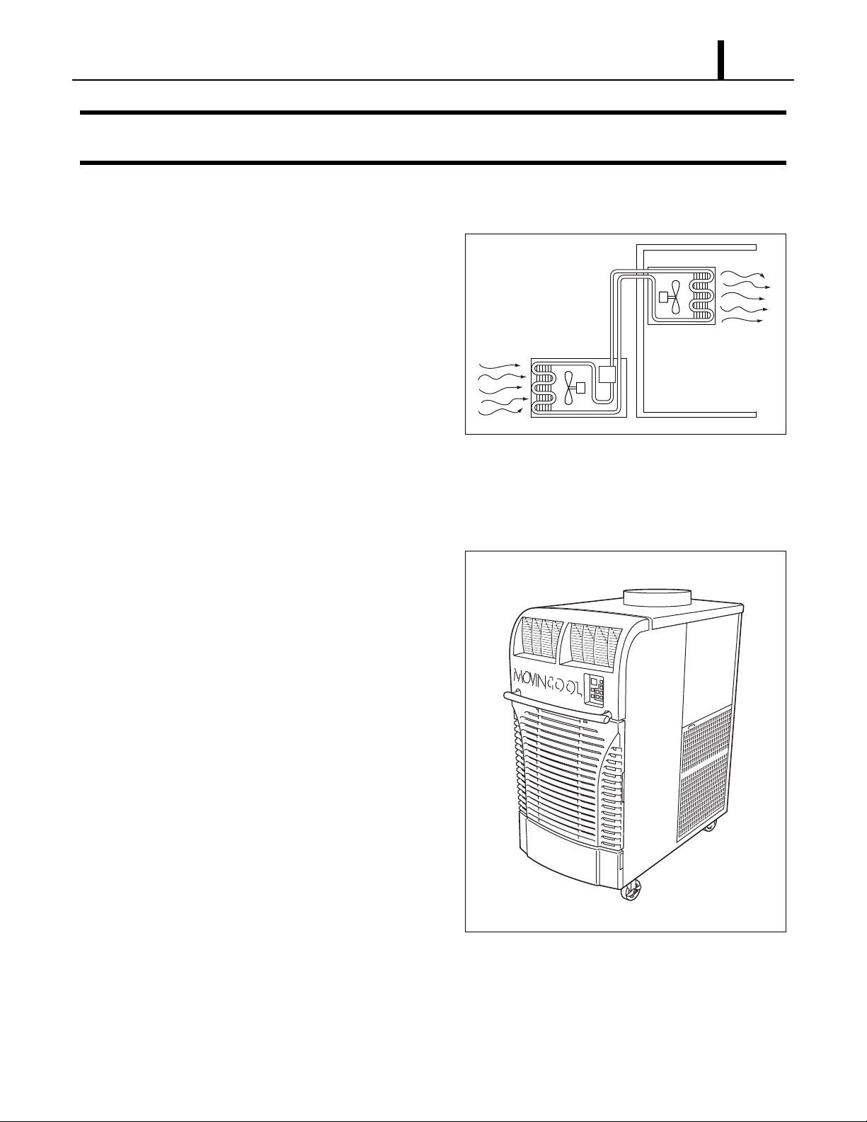
• In general, conventional air conditioners cool
the entire enclosed environment. They act as
“heat exchangers”, requiring an interior unit
(evaporator) to blow cool air into the interior
and an exterior unit (condenser) to exhaust
exchanged heat to the outdoors.
• Unlike conventional air conditioners, the
Condenser
(Outdoor Unit)
Operation Section
7
Evaporator
(Indoor Unit)
MovinCool Office Pro 63 is a spot cooler which
directs cool air to particular areas or objects.
MovinCool Office Pro 63 has the following features:
2.2 Compact Design
• The innovative design of MovinCool Office Pro
63 has resulted in one compact unit, replacing
the need for two separate units.
2.3 Easy Transportation and Installation
• With the whole cooling system built into one
compact unit, MovinCool Office Pro 63
requires no piping and can be easily
transported and installed.
I000501
2.4 Energy Conservation
• MovinCool Office Pro 63 is economical
because it cools only the area or objects which
need to be cooled.
I001905
8
Operation Section
3. CONSTRUCTION
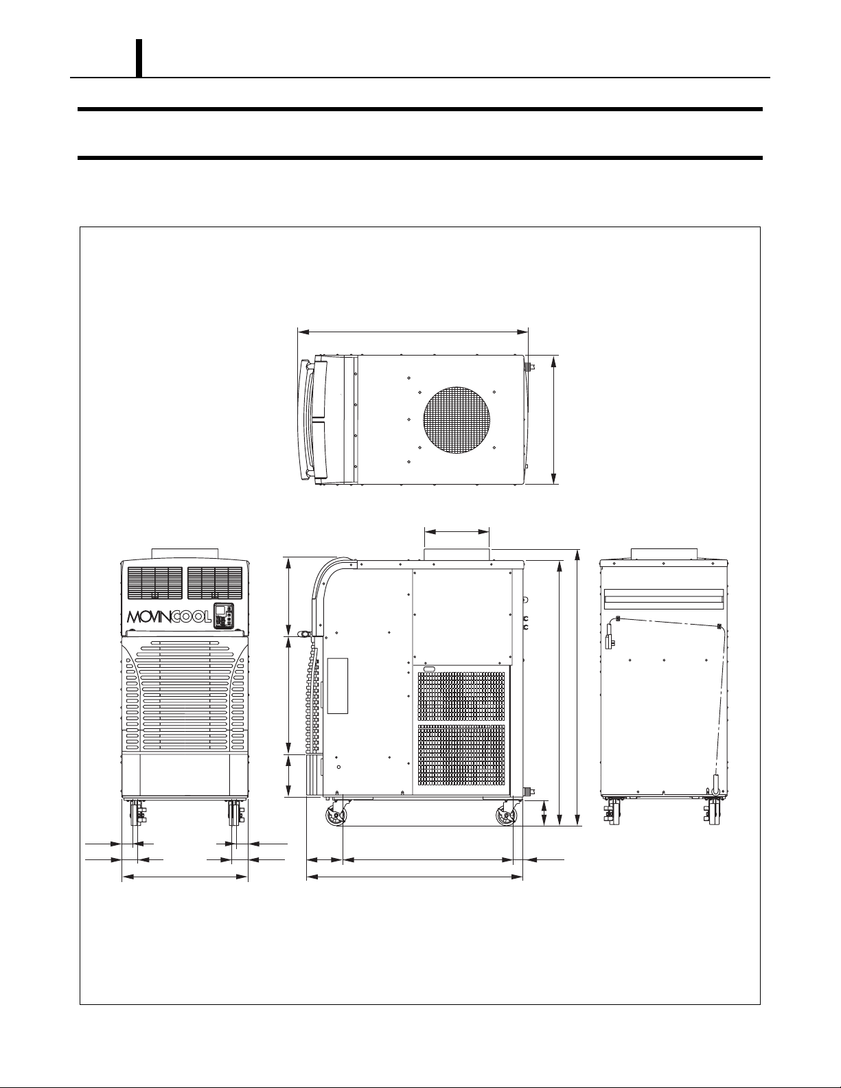
3.1 Exterior Dimensions
(55.0)
(30.2)
(2.6)
(3.6)
(29.9)
(2.6)
(3.6)
(18.7)
(27.6)
(10.0)
(8.5)
(40.8)
(51.6)
(DIA. 15.7)
(6.1)
(2.4)
(65.0)
(62.2)
(Unit: inch)
I001906
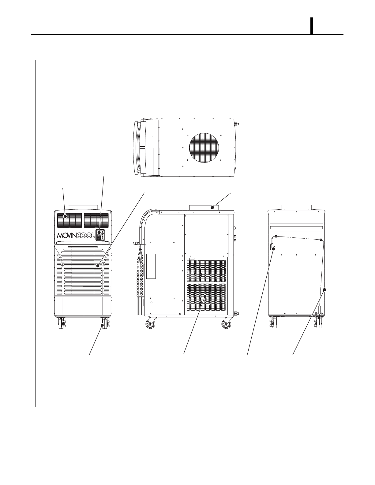
3.2 Exterior Components
Operation Panel
Operation Section
9
Cold Air Outlet Grill
Caster
Evaporator Air Inlet Grill
Condenser Air Outlet Duct
Service PanelPower CordCondenser Air Inlet Panel
I001907
10
Operation Section
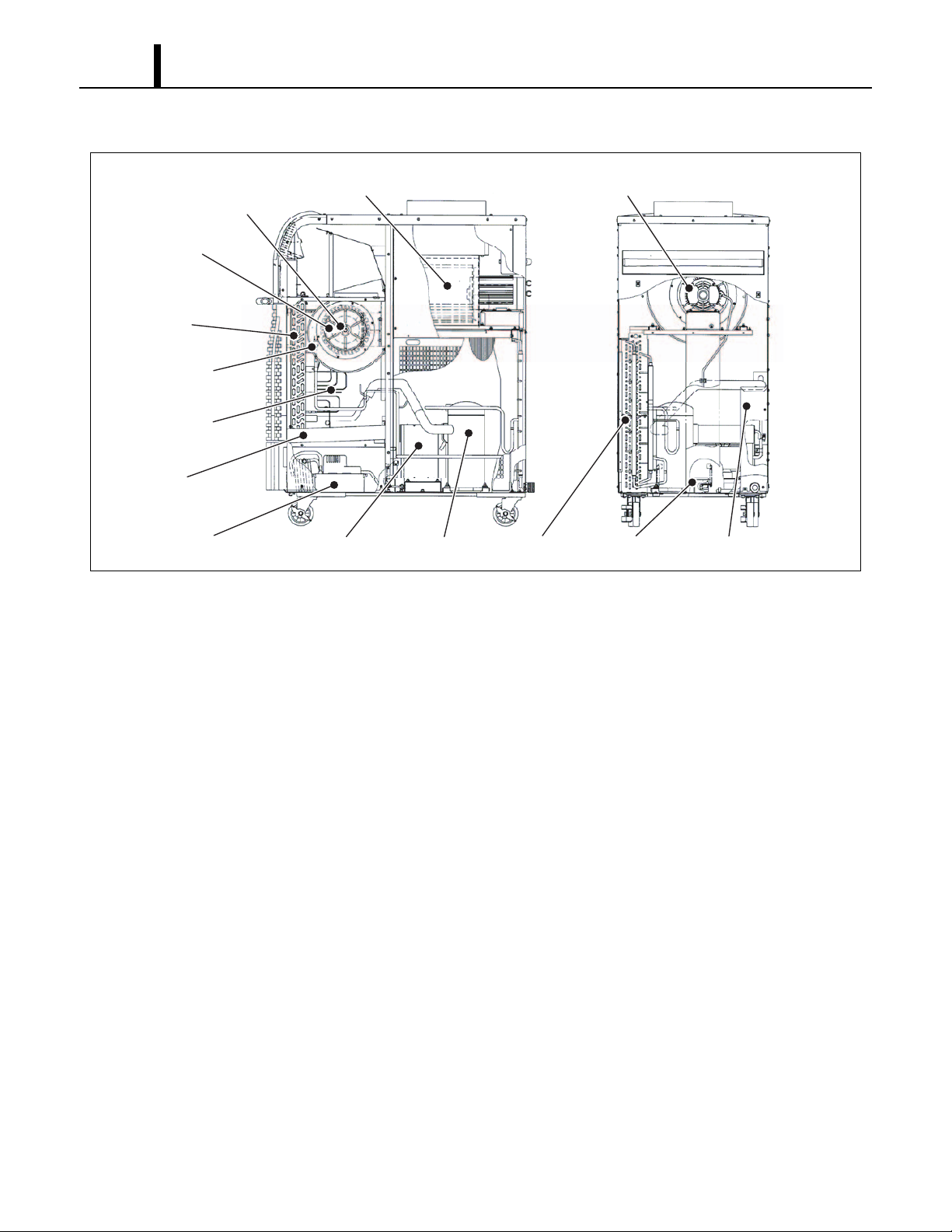
3.3 Internal Structure
Fan Motor
(Evaporator)
(Behind Fan)
Fan
(Evaporator)
Evaporator
High Pressure
Switch
Capillary Tube
Drain Pan
Fan
(Condenser)
TransformerCondensate Pump
3.4 Basic Construction
Compressor
Condenser
Fan Motor
(Condenser)
Drain Switch
Control Box
I001950
• The MovinCool Office Pro 63 is compact in construction because the condenser and the
evaporator are enclosed in one unit. The interior is divided into three sections. The upper front
face is equipped with the evaporator, and the lower front face contains the condensate pump
and optional drain tanks. The rear section contains the condenser, the compressor, the
transformer and the control box.
Operation Section
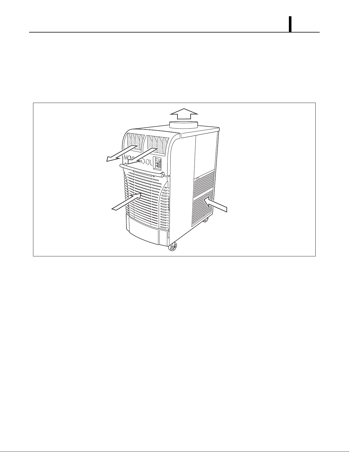
3.5 Air Flow
• Air drawn from the right side face passes through the condenser which extracts the heat. This
hot air is blown out through the upper exhaust air duct. Air taken in from the front face is cooled
by the evaporator and then blown through the cool air vent. All the air inlets are equipped with
filters, and the exhaust air duct is protected by metal grill.
Exhaust Air Out
Cool Air Out
11
Evaporator Air In
Condenser Air In
3.6 Electrical System
• The MovinCool Office Pro 63 is equipped with a compressor operated at 460 V, 3 phase and a
dry-type distribution transformer operated 460 V, single phase at primary side and 230 V single
phase at secondary side which supply power source for fan motors, relay board, and
condensate pump.
3.7 Compressor and Fans
• The compressor is hermetically sealed. Two sets of a two-speed fan motor with a centrifugal fan
are used to draw air across the evaporator and condenser.
I001909
3.8 Transformer
• The transformer is a dry-type distribution transformer rated 5 KVA at 460 V primary side and
230 V secondary side.

12
Operation Section
3.9 Condensate Pump
• The condensate pump and a 20 ft (6 m) drain hose are included with the Of fice Pro 63 to provide
continuous operation without the need of the drain tanks. The co ndensate pump has a maximum
head lift of 17 ft (5.2 m) at system operated voltage of 460 VAC.
3.10 Drain Tanks (optional)
• A set of two 5.0 gal (19 L) drain tanks are supplied as optional accessory for Office Pro 63. When
drain tanks are used instead of condensate pump , the condensate (water) is collected into both
tanks. The drain switch activates and stops the operation when tanks reach the level of
approximately 8.0 gal (30 L).
Operation Section
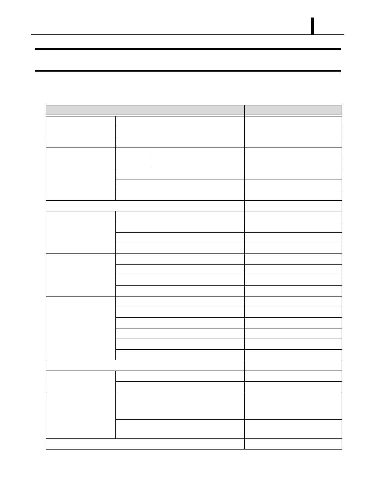
4. SPECIFICATIONS
4.1 Technical Specifications
ITEM SPECIFICATIONS
Electronic Features Control Panel Electronic
Thermostat Control Electronic
Cooling Capacity
Refrigerant Circuit Compressor Compression Type Hermetic Scroll
*1
Capacity 60000 Btu/h (17585 W)
Motor Rated Output at 460 V 3.89 kW
Evaporator Plate Fin
Condenser Plate Fin
Refrigerant Control Capillary Tube
13
Refrigerant/Enclosed quantity R-410 A/4.41 lb (2.00 kg)
Ventilation Equipment For
Evaporator
Fan Type Centrifugal
Max. Air Flow-high/low 1940/1770 CFM (3300/3000 m
Motor Rated Output-high/low at 230 V 0.60/0.33 kW
Max. External Static Pressure 0.9 IWG (224 Pa)
Ventilation Equipment For
Condenser
Fan Type Centrifugal
Max. Air Flow - high/low 2830/2650 CFM (4810/4500 m
Motor Rated Output-high/low at 230 V 1.2/0.92 kW
Max. External Static Pressure 0.85 IWG (212 Pa)
Electronic Characteristics Power Requirement 460 V, 3 PH, 60 Hz
MIN. MAX. Voltage MIN 414 V, MAX 506 V
Current Consumption
*1
Total Power Consumption
Power Factor
*1
*1
9.5 A
6.6 kW
87 %
Starting Current 65 A
Recommended Fuse size 20 A
Power Cord NEMA Plug Configuration L16-20
3
/h)
3
/h)
Gage x Length 12 AWG (4-core) x 6 ft
Signal Connection Fire Alarm Input • Dry contact type (recommended)
• No-Voltage Contact Input/Contact
resistance Less than 100 ohm
Warning Signal Output 2 A at 30 V (DC/AC) or less
(resistive load)
Net weight 705 lb (320 kg)
14
Operation Section
ITEM SPECIFICATIONS
Sound Level
Max. Duct Equivalent Length-Per Cold Duct )m 5.03/1.21( tf 001/04esoH tcuD toH/esoH
• Specifications are subject to change without notice.
< NOTE >
*1 :Rating Condition: 95 °F (35 °C), 60 %RH
*2 :Measured at 3.28 ft (1 m) from surface of unit.
*3 :Internal dry-type distribution transformer may produce a humming noise up to 31 dB(A) at maximum operated volt-
age (506 V) during stand-by state.
*2 *3
Discharge: 3/8 in (9.53 mm)
OD barbed
HR% 05 ,)C° 14( F° 501mumixaM :ria telnInoitidnoC gnitarepO
HR% 05 ,)C° 3.81( F° 56muminiM :ria telnI
)A(Bd 76/96wol/hgih-tcuD resnednoC htiW
)A(Bd 96/17wol/hgih-tcuD resnednoC tuohtiW
,W 57 ,A 5.0 ,V 032 ,PH 03/1pmuP etasnednoC
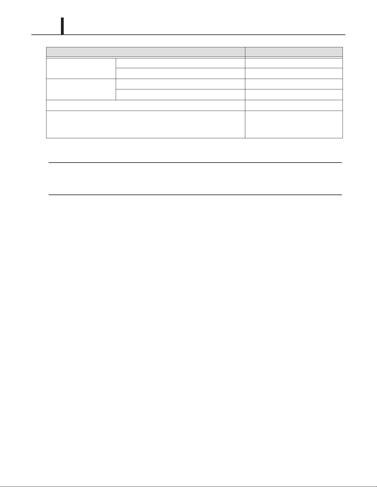
4.2 Characteristics
65
Btu/h)
60
3
Operation Section
15
>evruC ecnereffiD erutarepmeT riA looC<>evruC yticapaC gnilooC<
23.4(13)
21.6(12)
55
50
45
Cooling Capacity (x10
40
95(35)
86(30)
77(25)
68(20)
Dry Bulb Temp. °F (°C)
50
(10)
8.0
7.0
6.0
59
(15)
Wet Bulb Temp. °F (°C)
68
(20)
77
(25)
19.8(11)
18.0(10)
16.2(9)
14.4(8)
12.6(7)
Delta-T °F (°C)
10.8(6)
9.0(5)
7.2(4)
30 40 50 60 70 80
Relative Humidity (%)
>evruC noitpmusnoC tnerruC<>evruC noitpmusnoC rewoP<
12
10
8
5.0
Power Consumption (kW)
4.0
95(35)
86(30)
77(25)
68(20)
Dry Bulb Temp. °F (°C)
68
(20)
Wet Bulb Temp. °F (°C)
77
(25)
86
(30)
95
(35)
Current Consumption (A)
Dry Bulb Temp. °F (°C)
6
4
95(35)
86(30)
77(25)
68(20)
68
(20)
Wet Bulb Temp. °F (°C)
77
(25)
86
(30)
95
(35)
I001951
16
Operation Section
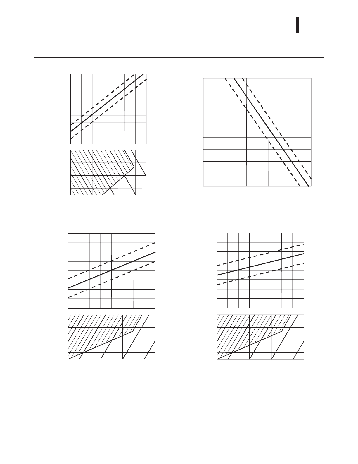
5. REFRIGERANT SYSTEM
5.1 Refrigerant System Construction
The component parts of the refrigerant system include the following:
• Compressor, Evaporator, Condenser, Capillary tube, High Pressure Switch
These parts are all connected by copper tubing. All the connections have been brazed.
Evaporator
Condenser
Evaporator Pipe
Compressor
Discharge Pipe
Condenser Inlet Pipe
Compressor
Capillary
Tubes
Condenser
Condenser
Fan
Evaporator
Fan
Capillary Tube
Evaporator Outlet Pipe
Compressor Suction Pipe
Condenser Outlet Pipe
Flow of Refrigerant
Evaporator
Compressor
I001952
Operation Section
5.2 Compressor
• The compressor used for the unit is hermetically sealed. The compressor and the compressor
motor are in one casing.
(1) Compressor theory of operation
• The scroll utilizes an involuted spiral which, when matched with a mating scroll form, generates
a series of crescent-shaped gas pockets between the two members. During compression, one
scroll remains stationary (fixed scroll) while the other form (orbiting scroll) is allowed to orbit (but
not rotate) around the first form. As this motion occurs, the pockets between the two forms are
slowly pushed to the center of the two scrolls while simultaneously being reduced in volume.
When the pocket reaches the center of the scroll form, the gas, which is now at a high pressure,
is discharged out of a port located at the center. During compression, several pockets are being
compressed simultaneously , resulting in a very smooth process. Both the suction process (outer
portion of the scroll members) and the discharge process (inner portion) are continuous.
17
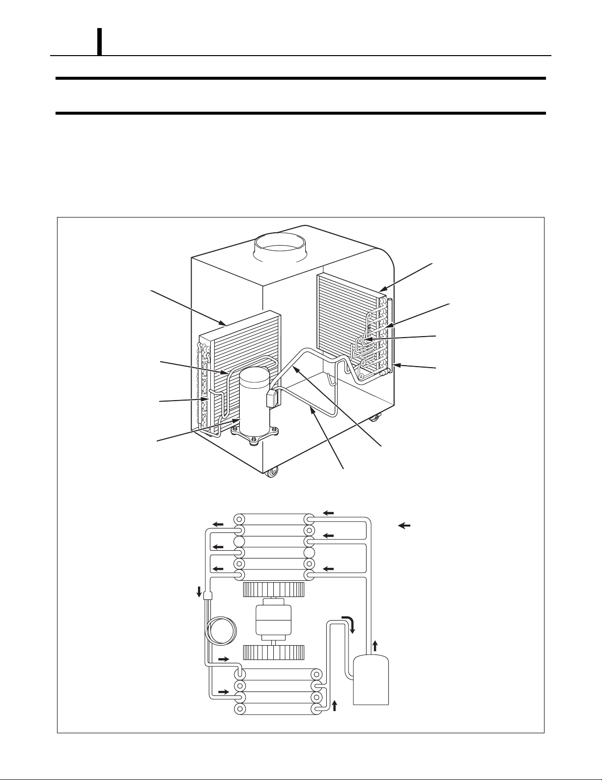
(2) Compressor operation
1㧕 3㧕 4㧕 5㧕2㧕
I001767
1) Compression in the scroll is created by the interaction of an orbiting spiral and a stationary spiral.
Gas enters the outer openings as one of the spirals orbits.
2) The open passages are sealed off as gas is drawn into the spiral.
3) As the spiral continues to orbit, the gas is compressed into two increasingly smaller pockets.
4) By the time the gas arrives at the center port, discharge pressure has been reached.
5) Actually, during operation, all six gas passages are in various stag es of compression at all times,
resulting in nearly continuous suction and discharge.
< NOTE >
When the compressor shuts off, the compressor motor may run backward for a moment or two
until internal pressures is equalized. This has no effect on compressor durability but may cause
an unexpected sound after the compressor is turned off and should not be diagnosed as a
malfunction.
18
Operation Section
5.3 Condenser
• The condenser is a heat exchanger with copper tubes that are covered with thin aluminum
projections called plate fins.
• Heat is given off and absorbed by air being pulled across the condenser fins by the centrifugal
fan and then expelled through the exhaust air duct.
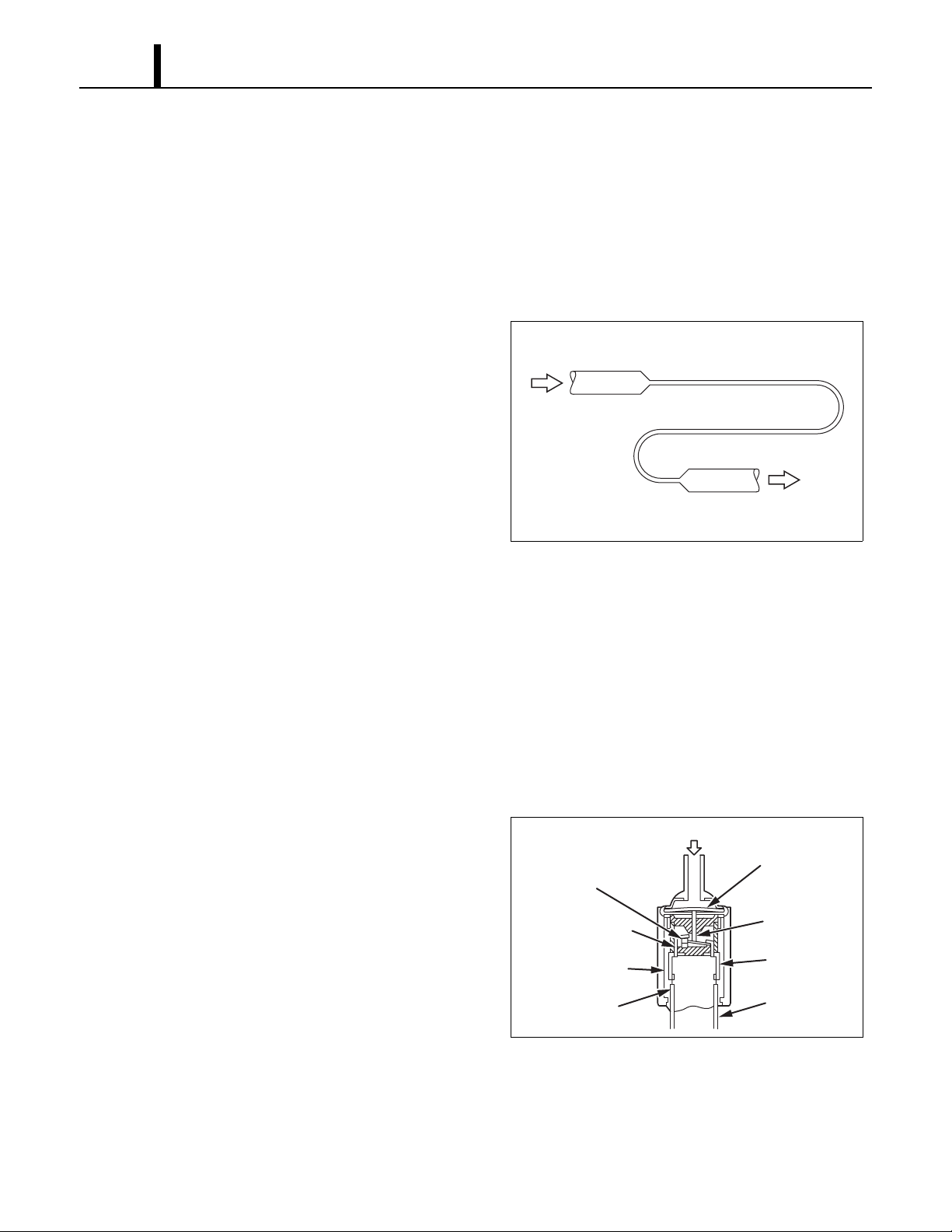
5.4 Capillary Tube
• The capillary tube is a long thin tube utilizing
line flow resistance to serve as an expansion
High Temp./High Pressure
Liquid Refrigerant
valve. The length and the inner diameter of the
capillary tube are determined by the capacity of
the refrigeration system, specified operating
conditions, and the amount of refrigerant. The
capillary tube causes the high pressure, high
temperature liquid refrigerant sent from the
Low Temp./Low Pressure
Gas and Liquid Mixture
condenser to expand rapidly as the refrigerant
is sprayed out through the fixed orifice in the capillary tube. As a result, the temperature and
state of the refrigerant becomes low and mist-like respectively, causing it to evaporate easily.
5.5 Evaporator
• The evaporator, like the condenser , is a heat exchanger covered with plate fins. Heat is removed
from the air being pulled across the evaporator by the centrifugal fan and the resulting cool air
is expelled through the cool air vent.
I001887
5.6 High Pressure Switch
• The high pressure switch prevents the
condenser and compressor from being
damaged by excessively high pressure in the
Movable Point
high pressure line of the refrigeration cycle.
The switch is normally closed. The snap disk
Stationary Point
responds to the variations in pressure and, if
pressure is abnormally high, the snap disk
moves down to push the pin down, causing the
Molding by Resin
internal contacts to open. This interrupts the
ground signal at the control board (J104 connector) which turns the compressor off.
• Possible causes of this trouble include:
- The condenser air filter is dirty, restricting air flow.
- The condenser blower is defective.
Pressure of Refrigerant
Case
Snap Disk
Pin
Terminal
Lead Wires
I001768
6. ELECTRICAL SYSTEM
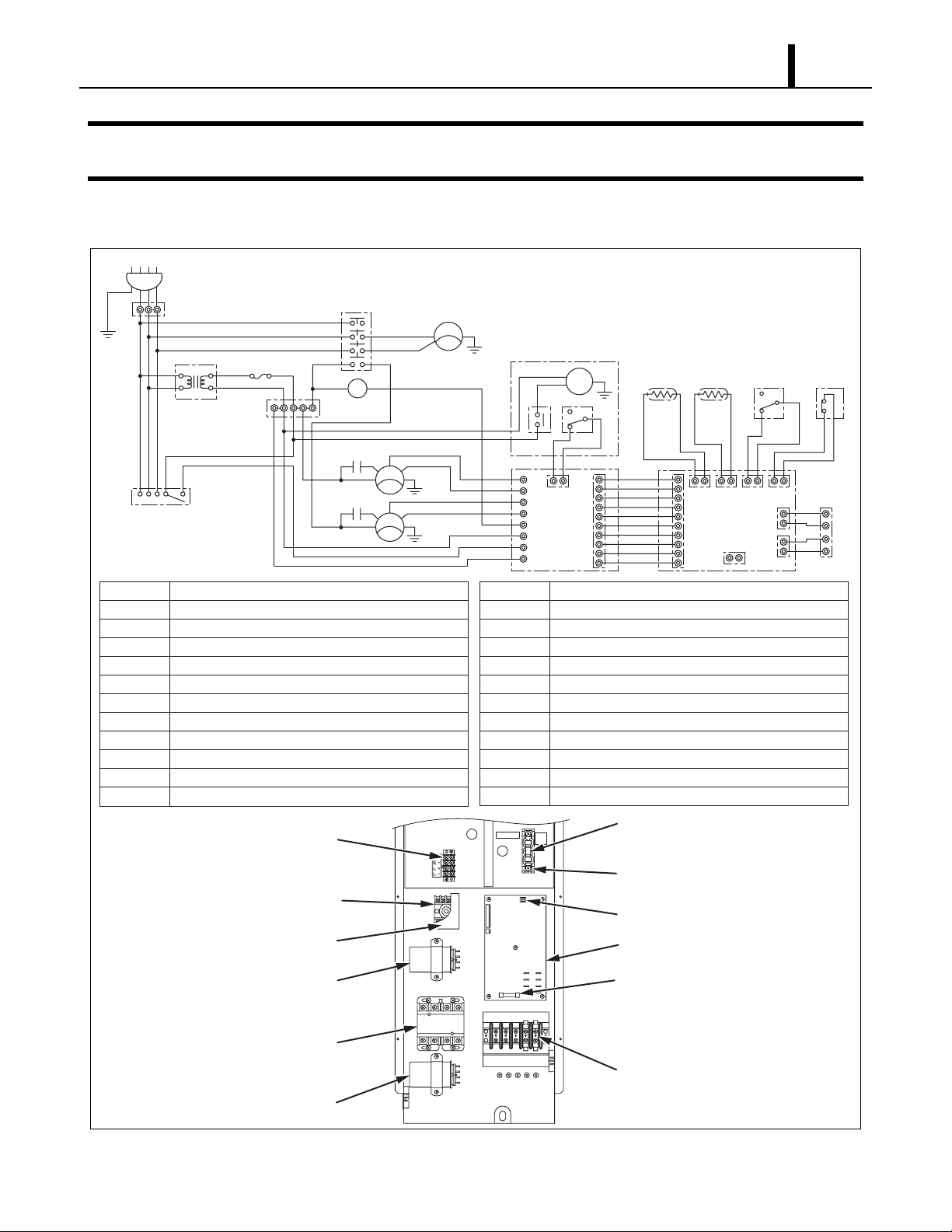
6.1 Circuit Diagram and Control Box
AC460 V 3 φ 60 Hz
AP
TSR
G
G
TB1
460 V 230 V
HI
H4 X1
345 1 8
RPHR
TNS
X4
F
1
2
S1 R1
1L1
3L2
5L3
7L4
A1 A2
TB1
MCC
MCC
CF2
12
CF1
12
2T1
4T2
6T3
8T4
HI
MF2
IOLF
HI
MF1
IOLF
LO
LO
MC
IOLC
G
G
G
J8
J7
J6
J5
J4
J3
J2
J1
Condensate Pump
MDP
ODS
FDS
J9
J10
RB
Operation Section
19
G
RTH THS
J101 J102 J103 J104
J201
CB
DS HPRS
3
2
J106
J108
J105
1
TB2
LL+
EE+
AP
TB1
TB2
CB
RB
MF1
MF2
MC
CF1
CF2
RPHR
TNS
Attachment Plug
Terminal Block
Terminal Block
Control Board
Relay Board
Condenser Fan Motor
Evaporator Fan Motor
Compressor Motor
Capacitor for Condenser Motor
Capacitor for Evaporator Motor
Phase Reversal Relay
Transformer
Terminal Block
(Signal Connection)
Terminal Block
(Reverse Phase Protector)
Reverse Phase Protector
Fan Capacitor
(Evaporator)
TB2
TB1
IOLF
IOLC
DS
THS
RTH
G
HPRS
MCC
MDP
FDS
ODS
F
FUSE 25A
Inner Overload Relay of Fan Motor
Inner Overload Relay of Compressor
Full Drain Warning Switch
Freeze Protection Thermistor
Room Thermistor
Grounding
High Pressure Switch
Relay for Compressor and Condenser Fan Motor
Condensate Pump Motor
Drain Float Switch
Drain Overflow Switch
Fuse (25 A)
Fuse
(for Transformer)
Fuse Holder
Dip Switch
Relay Board
Relay Board Fuse
Relay
Fan Capacitor
(Condenser)
G
Terminal Block
I001953
20
Operation Section
6.2 Basic Operation of The Office Pro 63 Electrical Circuit
• There are three basic components used to control the operation of the Office Pro 63 electrical
system:
- Transformer
- Control panel assembly
- Control box
• The control panel assembly contains the control panel, control board (with inputs for the freeze
and room temperature thermistors), drain switch, high pressure switch and a microprocessor.
(1) Fan mode
High Fan Mode
• When the FAN MODE button on the control panel is pressed, the microprocesso r turns on “F AN
HI” “COOL OFF” indication of LCD and activates both the fan on relay and fan mode relay. This
sends line voltage (230 VAC) from the fan on relay to the N.O. (normally open) contacts of the
fan mode relay. This output is connected to the J8 terminal (relay board) where the high speed
wire of the fan motor is connected.
• When this button is pressed again, fan turns to low mode (see below). Press again, fan stops.
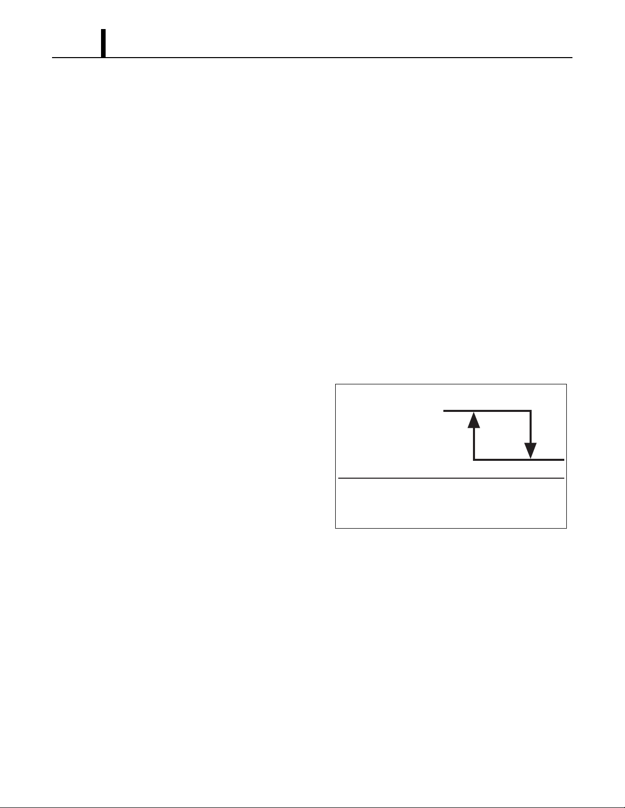
• High fan mode is automatically switched
depending on room temperature. When room
(High)
temperature is decreased down to 80 °F
(27 °C) or below, fan mode is switched to
Condenser Fan
HIGH. When room temperature is increased to
88 °F (31 °C) or higher, fan mode is switched
from HIGH to LO.
Room Temperature
(LO)
80 °F
(27 °C)
88 °F
(31 °C)
I001914
Low Fan Mode
• When the FAN MODE button on the control panel is pressed again, th e microprocessor turns on
“FAN LO” “COOL OFF” indication of LCD and activates both the fan on relay and fan mode relay.
This sends line voltage (230 VAC) from the fan on relay to the N.C. (normally closed) contacts
of the fan mode relay. This output is connected to the J7 terminal (relay board) where the low
speed wire of the fan motor is connected.
• When this button is pressed again, fan stops.

Operation Section
(2) Cool mode
• In addition to fan mode (as described above), when the COOL ON/OFF button on the control
panel is pressed, the microprocessor turns on “COOL ON” indication of LCD and if the
temperature set point is less than the current room temperature, activate s the compressor relay
(relay board) after 120 sec delay. This sends line voltage (230 VAC) to the J4 terminal (relay
board) and compressor auxiliary relay is excited. Then compressor and condenser fan motor
turn on (Cooling Operation).
• Condenser fan mode is automatically switched
21
depending on room temperature. When room
temperature is approximately. 100 °F (38 °C)
or greater, fan mode is switched LO to HIGH.
When room temperature is approximately.
95 °F (35 °C), fan mode is switched HI to LO.
(LO)
Condenser Fan
(High)
Room Temperature
95 °F
(35 °C)
100 °F
(38 °C)
I001915
22
Operation Section
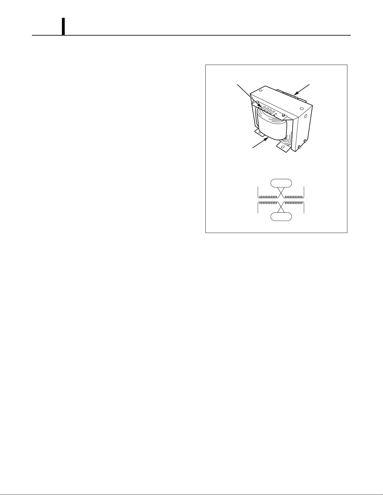
6.3 Transformer
• A dry-type transformer rated 5 KVA is equipped
within the unit to provide step down voltage
from 460 V single phase to 230 V single phase.
• The terminal connection of the primary side of
the transformer are labeled H1, H2, H3, and
H4. Terminals H2 and H3 are shorted together
to provide a series connection for 460 V
application. Terminals H1 and H4 are
connected to 460 V power source to supply
power to secondary side.
• T erminals X2 and X3 of the secondary side are
also shorted together to provide 230 V output
between terminals X4 and X1.
Specifications:
Distribution transformer
- Type: Dry type
- Rated VA: 5000 VA
Terminal Block
(Primary)
Coil
<Wiring Diagram>
Primary
(460 V)
Secondary
(230 V)
H1
Short Circuit
H3 H2 H4
Short Circuit
Terminal Block
(Secondary)
X1X2 X3X4
I001954
- Power Requirement: 1 PH, 60 Hz
- Primary Voltage: 460 V
- Secondary voltage: 230 V
6.4 Control Box
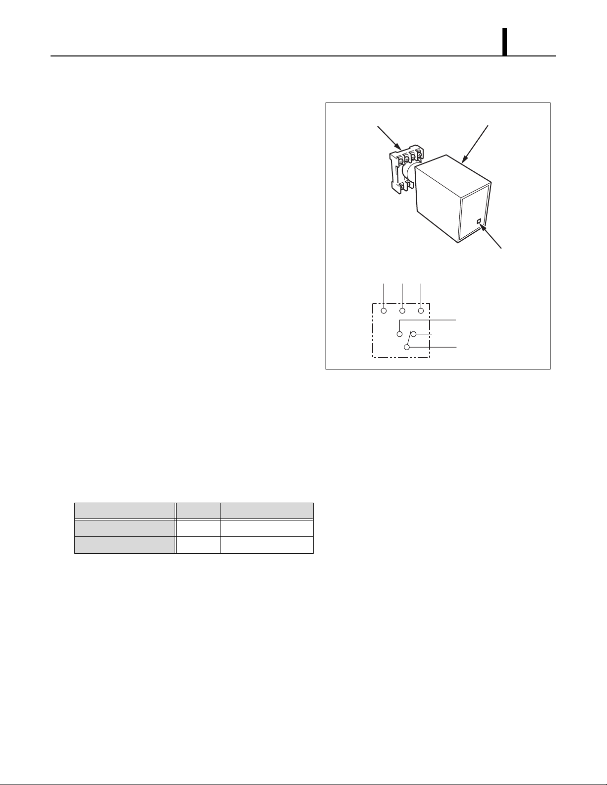
(1) Reverse Phase Protector
• The Reverse Phase Protector is operated at
nominal voltage of 440 VAC to 480 VAC.
The reverse phase protector is mounted on a
plug-in socket terminal block where it can
easily be plugged-in or removed during
service.
• The internal relay of a reverse phase protector
Terminal Block
Operation Section
23
Reverse Phase Protector
is energized and LED is on when the phase
sequence is correct. If the phases are reverse,
<Wiring Diagram>
RST
Power Source
LED
the out put relay will not energize.
3
45
• The reverse phase protector is reset
8
automatically upon correction of the fault.
Specifications:
- Rated Line Voltage: 440/480 V
to J2
(Normally Closed)
2
to TB1 R1
1
- Rated Output: 8 A resistive at 240 V
- Mounting: Plug-in socket (8 pin, octal plug)
(2) Capacitors
• The capacitors are used to temporarily boost the power output available to the fan motor at
start-up.
• The specifications of each capacitor are listed below:
Capacitor Application Voltage Rating Capacitance
Evaporator Fan Motor 440 VAC 15 µF
Condenser Fan Motor 370 VAC 25 µF
I001955
24
Operation Section
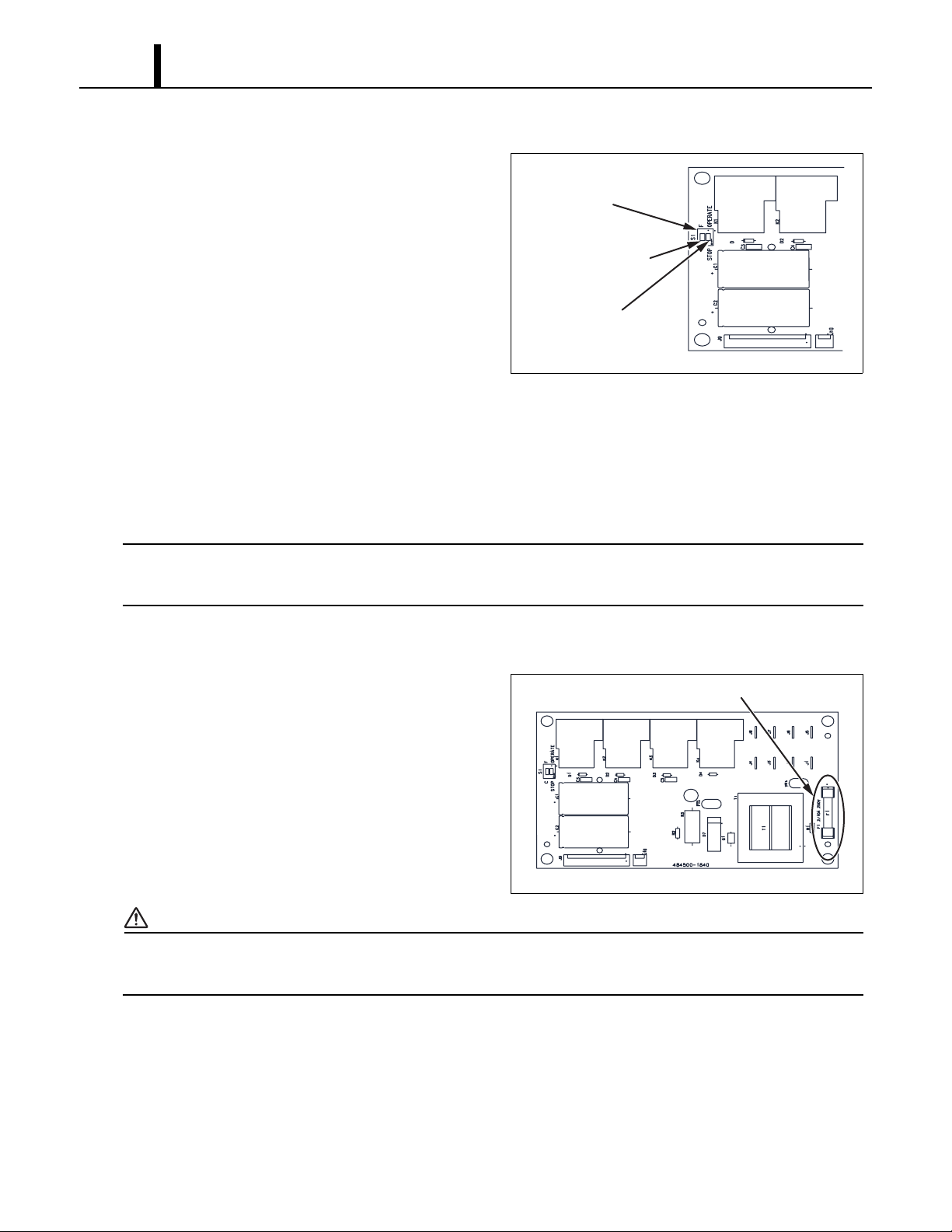
(3) Relay board
• The relay board receives signals and outputs
<Dip Switch>
from the control board that contains a
microprocessor. The relay board contains the
Dip Switch
compressor, fan on and fan mode (speed)
relays.
• It also contains a step-down transformer that
converts the line voltage (230 VAC) to 12 V.
• This 12 V is then converted from AC to DC and
Temperature Scale
Display Switch
(°C⇔°F)
Fan Mode Control
Switch
(STOP⇔OPERATE)
I001772
used for relay coil activation. The 12 V (DC)
power is sent to the control panel assembly where it is further reduced to 5 V for the system logic.
• The relay board also contains the DIP switch.
• The DIP switch is used to change the fan mode operation from stop to operate and change both
the set point and room temperature display from Fahrenheit to Celsius.
< NOTE >
The relay board must be serviced as a complete assembly. It has only one serviceable
component, the fuse. (see below)
(4) Relay board fuse
• This fuse provides protection against damage
to the step-down transformer. It must be
replaced with the exact type of fuse or an
equivalent.
Specifications:
- 2/10 A, 250 V
<Relay Board>
Fuse
CAUTION
Failure to use the exact type of fuse could result in damage to the unit and/or to components. It
could also void the warranty of the unit.
I001773
 Loading...