

Page 1
1. Inventory
After unpacking, please check to make sure you have the correct part number of the
switch assembly. If the switch assembly has incorrect part number or appear damaged,
please contact your MovinCool reseller for replacement (See Fig.1). Please keep this
installation manual with the operation manual for future reference.
1
INSTALLATION MANUAL
For Classic Plus 26 - Serial Number: 1200XXXX260 to 0307XXXX260
Switch Assembly (Part No. GX484560-2330)
Switch Assembly
Fig. 2
Fig. 1
2. Installation of Switch Assembly
WARNING: Disconnect power supply from the unit before performing any
service. Beware that some residual voltages may remain in the
unit immediately after the power is disconnected.
!
2-1. Connect the following connectors to the switch assembly (See Fig. 2):
A. J201 (10-pin) Wire Harness, relay board to the switch assembly.
B. J101 (2-pin) Room Temperature Thermistor.
C. J102 (2-pin) Freeze Protection Thermistor.
D. J103 (2-pin) Drain Tank Switch.
E. J104 (2-pin) High Pressure Switch.
A
B
C
DE
< NOTE >
• Connector J106, and J108 are not used.
Classic Plus 26
Manual P/N: GX484007-3720 First Issue: June 2012
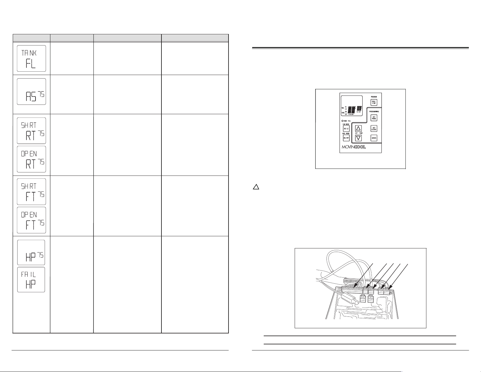
4. Self-Diagnostic Codes of Switch Assembly
LCD Display Description Condition Reset/Remedy
Drain tank is full. When the drain tank is filled
with drain water.
(“TANK FL” LED flashes.)
1)Drain away.
(LCD indicates “TANK”)
2)Press ON/OFF button.
HI
FAN
ON
COOL
HI
FAN
ON
COOL
HI
FAN
ON
COOL
Condensate pump
problem
F
SET TEMP
Defect (short or
open) of room
F
thermistor
SET TEMP
F
SET TEMP
When (optional) condensate
pump is damaged or broken.
When room thermistor
(connecting to J101) becomes
short or open.
1)Fix the condensate pump.
2)Reset the system.
To RESET: Press ON/OFF
and HI/LO buttons on the
control box simultaneously
for 5 seconds.
Disconnect and reconnect
the room thermistor.
If it does not work, then
change it.
HI
FAN
ON
COOL
F
SET TEMP
Defect (short or
open of freeze
protection
thermistor
When freeze protection
thermistor (connecting to
J102) becomes short or open.
Disconnect and reconnect
the freeze protection
thermistor. If it does not work,
then change it.
HI
FAN
ON
COOL
HI
FAN
ON
COOL
F
SET TEMP
Activation of high
pressure switch
F
SET TEMP
When high pressure switch
(connected to J104) activates
(=J104 input turns to open)
3 times in 24 hr, “HP” is
indicated. When it activates
10 times in 24 hours,
“FAIL HP” is indicated.
1. Check if the unit is
operating within the operating
temperature range.
2. Check air filter and clean
if needed.
3. Check condenser fan
motor and replace if defected.
4. Check high pressure
switch and replace if
defected.
5. Reset the system.
To RESET: Press ON/OFF
and HI/LO buttons on the
control box simultaneously for
5 seconds.
4
Page 2
3
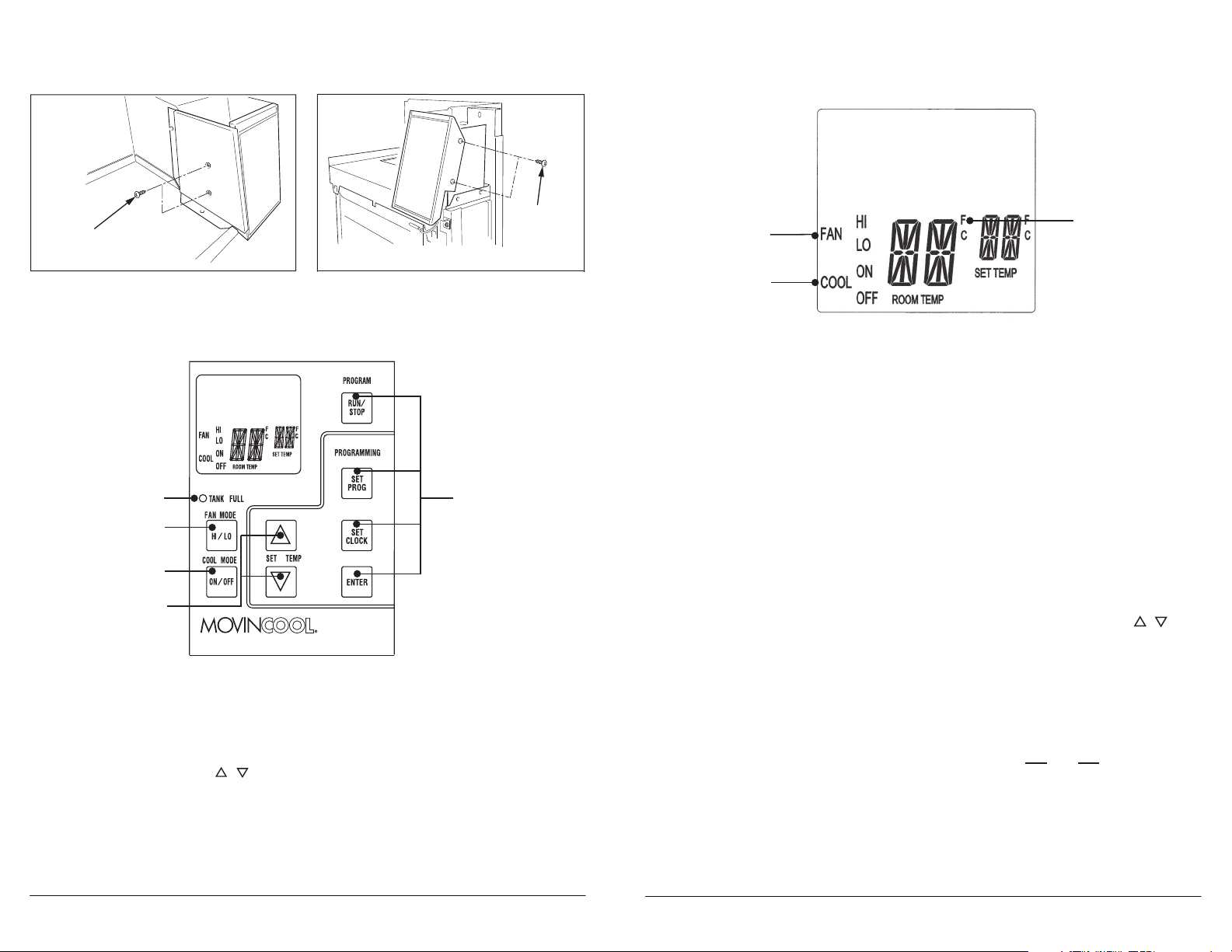
3. Operation of Switch Assembly (cont.)
3-2. LCD indicators (See Fig. 6)
Note: ROOM TEMP display range is from 16 °F (-9 °C) to 109 °F (42 °C).
When the display value is greater than 99 °F, it displays values of +0 (for 100 °F),
+1 (for 101 °F), and +9 (for 109 °F).
(This only applies to Fahrenheit values.)
6. FAN HI/LO Illuminates to indicate selected fan speed.
7. COOL ON/OFF Illuminates to indicate cool on or off.
8. °C or °F Temperature displayed in either Fahrenheit or
Celsius (See Note).
7
8
6
3-3. Operating in COOL Mode
1. The unit can be operated in COOL mode by pressing the COOL ON/OFF button
(LCD indicates “COOL ON”).
Note: In COOL mode the unit can only be turned off by pressing the COOL
ON/OFF button.
2. Change the fan speed by pressing the FAN HI/LO button.
3. Change the temperature set point by pressing the SET TEMP buttons ( / ).
Note: When turning the unit on, the set point and fan speed are determined by
the last operating mode.
Fig. 6
3-4. Operating in FAN ONLY Mode
1. The unit can also be operated in FAN ONLY mode by pressing FAN HI/LO
button (LCD indicates “FAN HI/LO” and “COOL OFF”).
2. The unit can then be turned off by pressing the FAN HI/LO button until fan
turns off (FAN ONLY mode speed sequences are HI > LO > OFF).
3-5. Changing from FAN ONLY Mode to COOL Mode
The COOL mode can be activated while the unit is operating in FAN ONLY mode.
To do this, simply press the COOL ON/OFF button (LCD indicates “COOL ON”).
Note: The FAN ONLY mode does not operate after the COOL mode has been
activated. The unit can only be turned off by pressing the COOL ON/OFF button.
2-2. Install four (4) screws to secure the switch assembly to the stays on the unit (See
Fig. 3 and Fig. 4).
Screws (2)
Screws (2)
Fig. 3 Fig. 4
3. Operation of Switch Assembly
3-1. Before operating the unit, it is important to familiarize yourself with the basic
control functions of the switch assembly (See Fig. 5).
4
2
1
3
Classic Plus 26
5
Fig. 5
1. COOL Mode Button
2. FAN Mode Button Activates/deactivates the high, low, and off fan
3. SET TEMP Buttons ( / )
4. TANK FULL LED Flashes when drain tank is full.
5. NOT USE These buttons are covered by the unit top cover.
Activates/deactivates the COOL mode/turns the
unit off.
speed.
Temperature scale illuminates to indicate the
current LED temperatures being displayed are
either in °C or °F.
2
 Loading...