

Page 1
INSTALLATION MANUAL
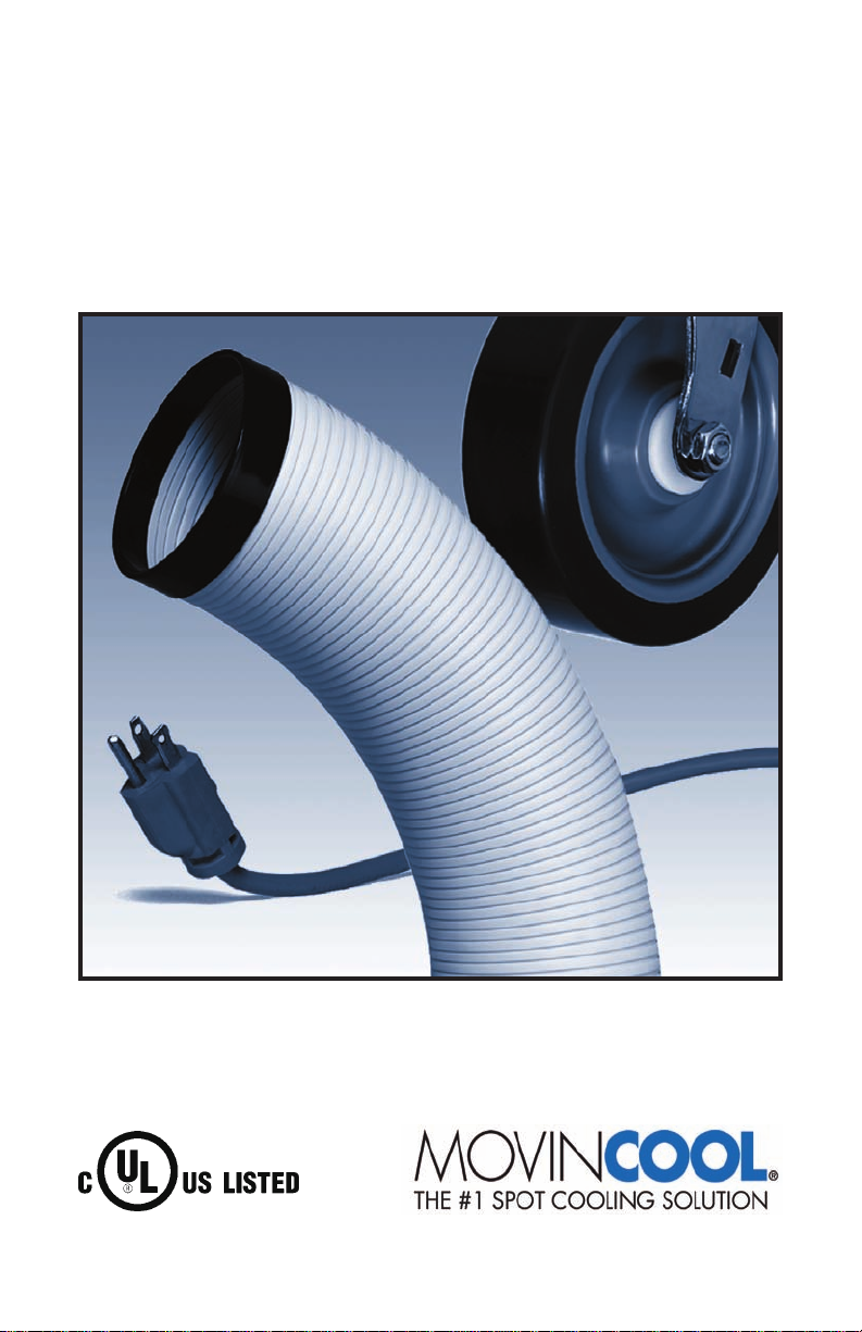
CONDENSATE PUMP
READ THIS MANUAL CAREFULLY FOR INSTRUCTIONS ON CORRECT
INSTALLATION AND USAGE, AND READ ALL SAFEGUARDS.
Page 2

© 2008 DENSO SALES CALIFORNIA, INC.
All rights reser ved. This book may not be reproduced or copied,
in whole or in part, without the written permission of the publisher.
DENSO SALES CALIFORNIA, INC. reserves the right to make changes
wit hout p rior n otic e. MovinCool is a re gist ere d trad emar k of
DENSO Corporation.
Page 3

FOREWORD
Congratulations on purchasing a MovinCool Condensate Pump.
This manual explains how to install the condensate pump onto
MovinCool units. Please read this installation manual thoroughly to familiarize yourself with the features of the unit and to ensure years of reliable
operation. You may also find it useful to keep this installation manual on
hand for reference.
Components and/or procedures are subject to change without prior
notice.
Definition of Terms
! WARNING: Describes precautions that should be observed to prevent injury to the user during installation or unit operation.
! CAUTION: Describes precautions that should be observed to prevent
damage to the unit or its components, which may occur during installa-
tion or unit operation if sufficient care is not taken.
Note: Provides additional information that facilitates installation or
unit operation.
• Para Español, visita www. movincool.com
• Pour le français voit la www.movincool.com
GENERAL WARNINGS & CAUTIONS
• All electrical work, if necessary, should only be performed by quali-
fied electrical personnel. Repair to electrical components by non-cer-
tified technicians may result in personal injury and/or damage to the
unit. All electrical components replaced must be genuine, MovinCool
or DENSO brand purchased from an authorized reseller.
• Do not handle the pump with wet hands or when standing in water
as fatal shock could occur. Disconnect all power from the MovinCool
before servicing the unit for any reason.
• Protect the power cable from coming in contact with sharp objects.
• Do not kink or allow power cord to come in contact with oil, grease,
chemicals, or hot surfaces.
• To reduce risk of electrical shock, connect MovinCool unit to a prop-
erly grounded terminal.
3
Page 4
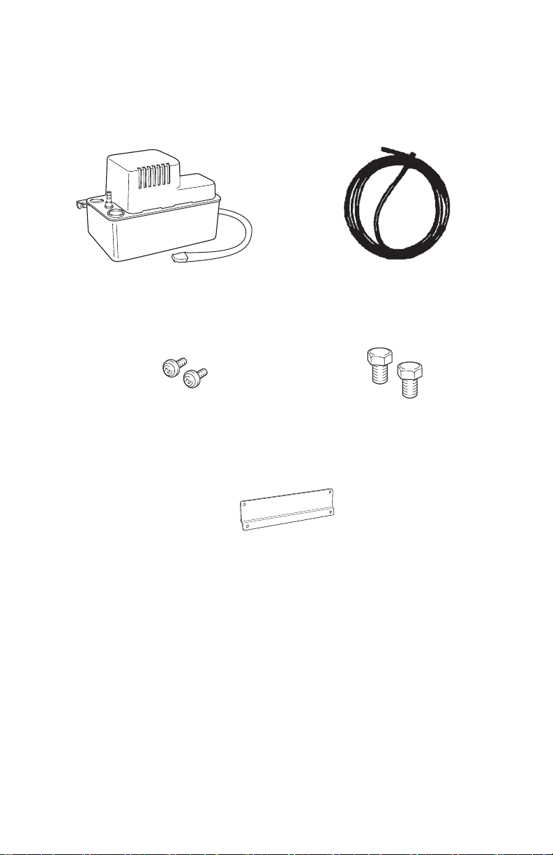
INVENTORY
After unpacking your Condensate Pump Kit, please check to make sure
you have the following items:
Condensate Pump (1) Hose, 3/8 inch (9.5mm) diameter,
20 feet(6m)
Small Screws (2)
(Not required for Office Pro 36)
Adapter Plate
(Not required for Office Pro 36)
Note: If any of these items are not included in the box or appear
damaged, please contact your MovinCool reseller for replacement.
Bolts (2)
4
Page 5

PREPARATION
Remove Condensate Pump from
package.
! WARNING: Make sure the
MovinCool unit is unplugged
from the electrical outlet or if
permanently wired, make sure
circuit breaker is in the off
position.
PUMP INSTALLATION
Secure pump to adapter plate
using the two screws supplied in
the kit.
Mount the Condensate Pump
assembly to the rear inside panel
(as shown) using the two bolts
supplied in the kit.
5
Page 6

PUMP INSTALLATION
Remove jumper plug from mating
connector. Connect pump to mating connector on inside panel or
to adapter harness.
Note: 115v and 230v pumps
have unique connectors.
For Office Pro 36 Only
Plug pump connector into matching connector in rear frame.
Slide pump mounting tab between
side panel and back holder.
6
Page 7

PUMP INSTALLATION
Secure pump to side panel with
the screw provided.
115V Pump Connector
Note : Refer to MovinCool Accessory Guide for proper pump’s selection.
230V Pump Connector
7
Page 8

PUMP INSTALLATION
REMOVE
Remove tab from pump.
HOSE INSTALLATION
Note: The Condensate Pump Kit
is equipped with a 20 foot(6m)
hose. This hose will be used as
both a drain and an inlet hose
for the Condensate Pump.
Cut a section of the 20-foot(6m)
hose sufficient enough (approx. 9
in or 23cm) to connect drain pan
to condensate pump drain hole.
Connect one end of the
section hose to the MovinCool
drain stem.
Insert the other end of the section
hose into the condensate pump
drain hole.
Connect the remainder of the 20foot(6m) hose to the drain outlet
spout.
DRAIN STEM
DRAIN
HOSE
(9"or 23cm)
9"(23cm)
DRAIN HOSE (20' or 6m)
DRAIN HOLE
8
Page 9

HOSE INSTALLATION
DRAIN HOSE
DRAIN STEM
DRAIN HOLE
DRAIN HOSE
For Office Pro 36 Only
Connect the remainder of the 20
foot (6 m) hose to the drain outlet
spout and feed it through the
grommet on the right hand side of
the unit.
Note: Please check the drainage
performance after installation. It
is important that the drainage line
from the pump is free of kinks and
is not pinched.
Power fluctuation or low voltage
could result in incorrect drainage.
To ensure proper drainage,
locate the highest vertical posi-
tion, no more than the maximum head lift which shown in the table
below, and run the drain hose on a downward slope at a minimum
rate of 1/4 inch(6.25mm) per foot .
1/4" TAPER
PER FOOT
DRAIN HOSE
Less than Maximum head lift
CONDENSATE
PUMP
230V Pump
115V Pump
230VAC
208VAC
Maximum head lift
20 feet (6m)
17 feet (5.2m)
13 feet (4m)
9
Page 10

MAINTENANCE & TROUBLESHOOTING
3/8" I.D. DRAI N
OUTLET SPOUT
WITH CHECK VALVE
MOTOR FAN
COVER
RESERVOIR
DRAIN TANK OVERFLOW
SWITCH FLOAT
MAIN CONTROL
FLOAT
MOUNTING EAR
1" INLET
DRAIN HOLE
! WARNING: When performing any maintenance and/or troubleshooting, make sure that all electrical power is off. This means before service,
unplug the unit from the electrical outlet or if permanently wired, make
sure the circuit breaker is in the off position.
1) Remove any dirt or debris which may collect in the bottom of the
reservoir tank.
2) On a monthly basis, check the condensate drain hose for kinks,
blockage or any other damage that may obstruct condensate pump
from draining properly.
3) Always replace the fan motor cover to keep electrical parts free of
dust, dirt and any other foreign material.
Drain Tank Overflow Switch
This safety feature will stop the compressor operation if the pump
malfunctions. To test the drain tank overflow switch, pinch the drain outlet
hose and pour water into the reservoir inlet drain hole. Continue to fill
the reservoir until the rising water lifts the overflow switch and stops the
operation.
Note: If the Fan Mode Control DIP Switch is set to the “STOP”
position, the entire unit (including fan operation) will turn off.
If the compressor continues to operate when the reservoir is full, check
your installation procedure. After testing is complete, release the drain
outlet hose and the condensate pump will empty the reservoir. Make sure
the 9 in(23cm) section of hose is installed into the inlet drain hole of the
pump reservoir.
Condensate Pump
10
Page 11

DENSO SALES CALIFORNIA, INC.
Long Beach CA 90810-1868
www.movincool.com
GAC P/N: LA484007-1751 Second Issue: February 2008
 Loading...