

Page 1
OPERATION MANUAL
U
L
US LISTED
C
CM12
READ THIS MANUAL CAREFULLY FOR INSTRUCTIONS ON CORRECT
INSTALLATION AND USAGE, AND READ ALL SAFEGUARDS.
Page 2
© 2006 DENSO SALES CALIFORNIA, INC.
All rights reserved. This book may not be reproduced or copied,
in whole or in part, without the written permission of the publisher.
DENSO SALES CALIFORNIA, INC. reserves the right to make changes
without prior notice. MovinCool is a registerd trademark of
DENSO Corporation.
Page 3

Table of ConTenTs
FOREWORD ............................................................................................ 1
GENERAL WARNINGS & CAUTIONS ................................................... 1
INVENTORY ............................................................................................. 2
INSTALLATION ........................................................................................ 2
Unit Overview ................................................................................... 2
Clearance Requirement ................................................................... 3
Mounting to Roof Structure ............................................................ 4
Power Supply Requirement ............................................................5
Service Panel Access ...................................................................... 5
Power Connection ........................................................................... 6
Drain Hose Connection ................................................................... 6
Packing Attachment ........................................................................ 8
Thermostat Connection .................................................................. 8
Warning Signal Connection............................................................. 9
Fire Alarm Control Panel Connection .......................................... 10
Dip Switch Setting ......................................................................... 10
Ducting with Typical Drop Ceiling ................................................ 11
FEATURES ............................................................................................. 12
DAILY INSPECTION & MAINTENANCE ............................................... 13
TROUBLESHOOTING ........................................................................... 13
Installation Check Sheet ...............................................................14
TECHNICAL SPECIFICATION .............................................................. 15
Page 4

foReWoRD
Congratulations on purchasing the MovinCool CM12.
This manual explains how to assemble, install and operate the MovinCool CM12 air conditioning unit. Please read this operation manual thoroughly to familiarize yourself with the
features of the unit and to ensure years of reliable operation. You may also find it useful to
keep this operation manual on hand for reference.
Components and/or procedures are subject to change without prior notice.
Definition of Terms
WARNING: Describes precautions that should be observed in order to prevent
injury to the user during installation or unit operation.
CAUTION: Describes precautions that should be observed in order to prevent
damage to the unit or its components, which may occur during installation or unit
operation if sufficient care is not taken.
NOTE: Provides additional information that facilitates installation or unit operation.
• Para Español, visita www. movincool.com
• Pour le français voit la www.movincol.com
GeneRal WaRnInGs & CaUTIons
• All electrical work should only be performed by qualified electrical personnel. Repair
to electrical components by non-certified technicians may result in personal injury
and/or damage to the unit. All electrical components replaced must be genuine MovinCool parts, purchased from an authorized reseller.
• Installation should be conducted by qualified technician only and DENSO and
DENSO affiliate are not responsible for injuries and/or damages caused by improper
installation.
1
Page 5
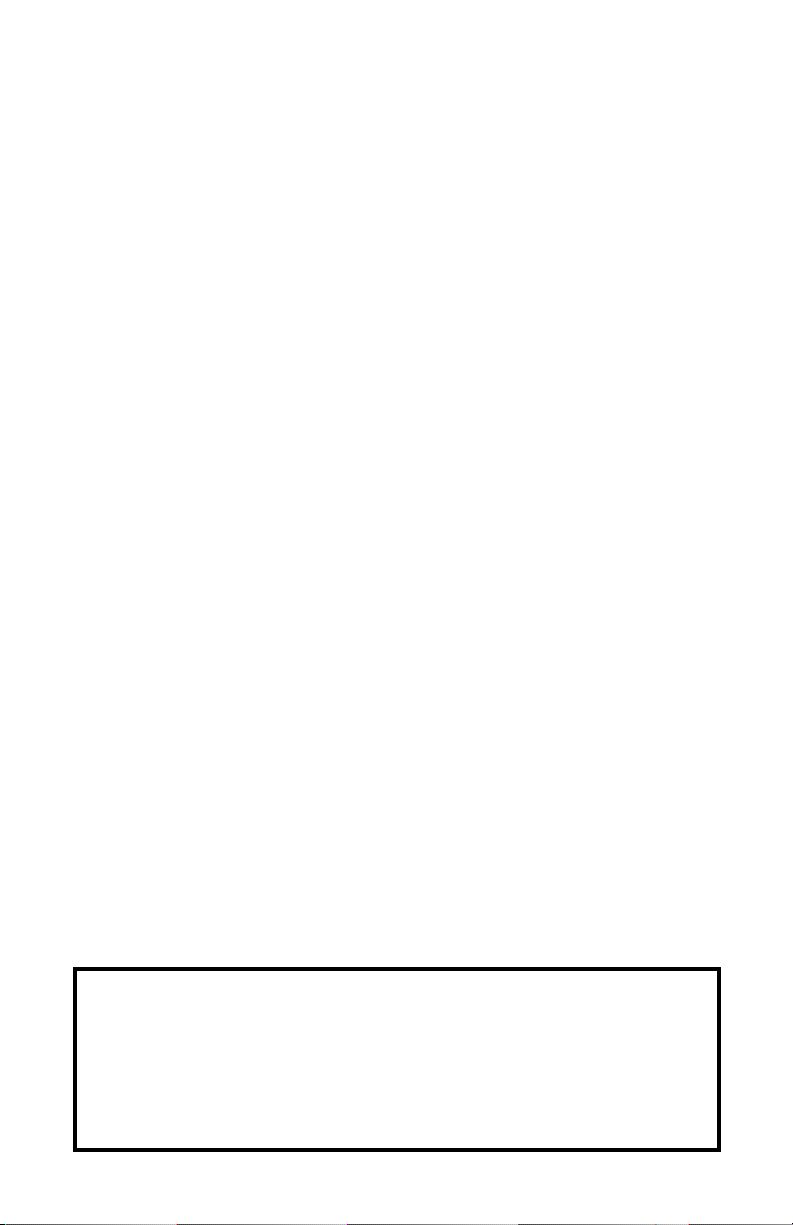
InVenToRY
OPERATION
MANUAL
CM12 UNIT
CONDENSATE PAN
DRAIN FOR
MAINTENANCE
CO
LD AIR EXHAUST
(10 IN. DIA. FLANGE)
EVAPORATOR (ROOM)
AIR INTAKE
(10 IN. DIA. FLANGE)
MOUNTING
BRACKETS
DRAIN PIPE
FOR PUMP
CONDENSER (HOT)
AIR EXHAUST
CLIP
PA
CKING II (1 IN. X 33 IN. X 0.2 IN.)
P
ACKING I (2.75 IN. X 32 IN. X 0.2 IN.)
After unpacking your MovinCool unit, please check to make sure you have the following
items:
• CM12 MovinCool Unit (1)
• Operation Manual/Warranty Card (1)
• Clip (1)
NOTE: If any of these items were not included in the box or appear damaged, please
contact your MovinCool reseller for replacement.
• Packing I (1)
• Packing II (1)
InsTallaTIon
Unit Overview
2
Page 6
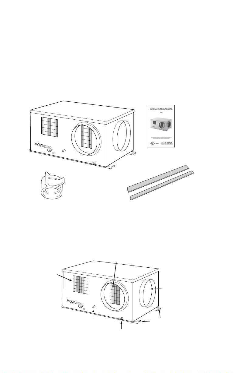
InsTallaTIon
WALL
CEILING
WALL
WEIGHT: 121 LBS
All dimensions are in inches
INTAKE
EXHAUST
33.62
31.97
34.80
ø0.55
ø10.00
15.67
17.64
19.92
Minimum
clearance
40 inch
from wall
Minimum
clearance
40 inch
from wall
2.68
15.31
15.40
7.49
8.68
0.59
4.06
2.77
1.97
10.00
9.21
Top of the unit should not contact
any building structure or object.
CONDENSER AIR INTAKE
SERVICE PANEL
SIGNAL WIRE
OVERRIDE (STOP)
SWITCH
POWER CORD
CONNECTION
WARNING: Remove protective cardboard from condenser intake after installation.
Clearance Requirement
3
Page 7
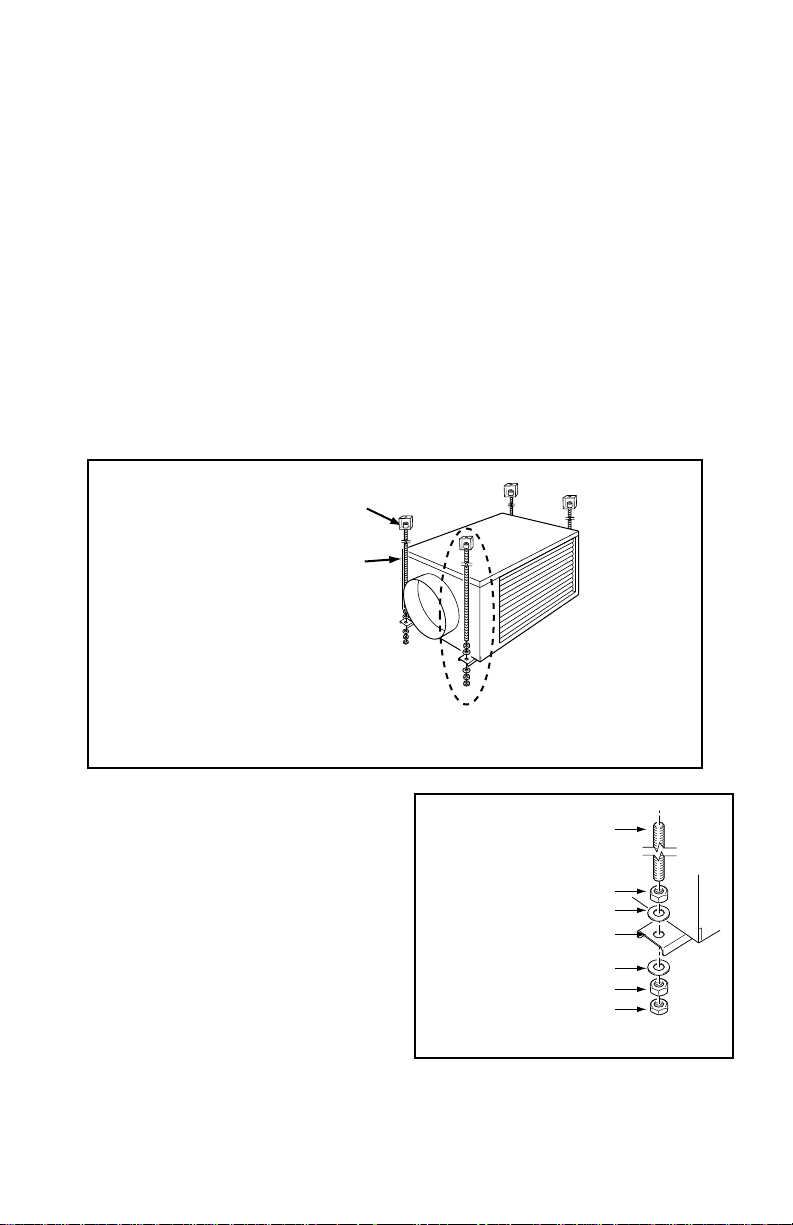
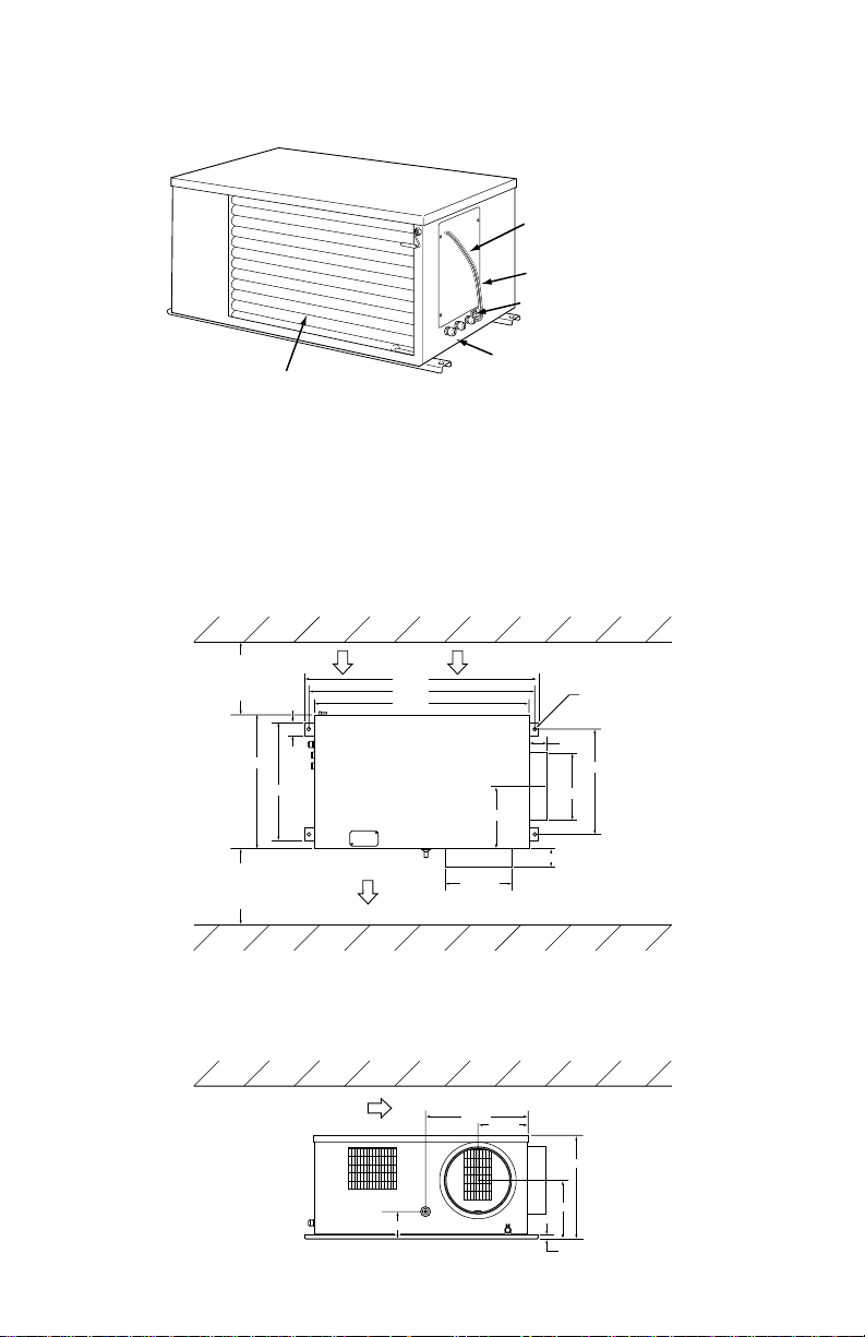
InsTallaTIon
VIBRATION ISOLATOR
(MIN 125 LBS. LOAD CAPACITY)
1/2 IN. THREADED ROD
(MIN 125 LBS. LOAD CAPACITY)
ALL MOUNTING HARDWARE FIELD PROVIDED
SEE MOUNTING DETAIL
1/2” THREADED ROD
(MIN 125 LBS. LOAD CAPACITY)
1/2” NUT
1/2” NUT
1/2” JAM NUT
1/2” WASHER
1/2” WASHER
MOUNTING BRACKET
Mounting the CM12 to a Roof Structure
WARNING: Be sure that the supporting roof structure is capable of supporting the
weight of the unit, mounting hardware and the accessories (Roof structure should
be capable to support four times of total weight or more. Unit weight is 121 lbs).
Be sure to securely anchor the top ends of the suspension rods. Make sure all nuts
are tight. Be sure to follow all application codes.
The CM12 unit is usually mounted above the ceiling and must be securely mounted to the
roof structure. The ceiling support of the existing building may require reinforcements.
Use field-supplied threaded 1/2 inch suspension rods, washers, nuts and vibration isolators.
The recommended clearance between ceiling grids and building the structural member is
the unit height plus 3 inches.
Install the four field-supplied rods by
suspending them from suitable building
structure members. Locate the rods so that
they will align with four mounting holes in
the mounting bracket that are part of the unit
base.
Wear gloves to avoid injury during installation
Tightening torque for nuts: 33lbf•ft
CAUTION: Make sure the unit is level
(must be less than 2˚ incline).
4
Page 8

Power Supply Requirements
CIRCUIT BREAKER WITH
GROUND-FAULT PROTECTIVE
FUSE 20A MAX.
TERMINAL BLOCK OF CM12 GROUND TERMINAL
R T G
R T
G
• The CM12 requires a single-phase 115V, 60Hz power supply to operate.
• The power supply should be a dedicated single outlet circuit with a UL approved
short-circuit and ground fault protective breaker with a fuse size of 20A maximum.
Service Panel Access
Access service panel by removing 4 screws.
Tightening torque for screw is 0.8 lbf•ft.
5
Page 9

Power Connection
DRAIN PIPE
CONDENSATE PAN
DRAIN FOR
MAINTENANCE
R T I
Connecting Power Supply to Unit
The following are recommended wire sizes
and electrical ratings:
• Cord Type: SJT (3 wires) or equivalent
• Wire Gauge: 14 AWG
• Voltage Rating: 300V min
• Heat Resistance: 60˚C
• Remove service panel from the right
side of CM12 unit.
• Route power cord wires through the
opening of the left grommet connector
located below service panel. Tighten
the grommet connector at about
2.17lbf•ft torque.
• Connect the neutral wire (white color label “R”) to the left screw connection of terminal block. Tighten screw at about 0.96lbf•ft torque.
• Connect the line wire (black color label “T”) to the center screw connection of terminal block. Tighten screw at about 0.96lbf•ft torque.
• Connect the ground wire (green color label “G”) to brass screw located below terminal block. Tighten screw at about 0.96lbf•ft torque.
WARNING: All electrical work should only be performed by qualified personnel.
Repair to electrical components by non-certified technicians may result in personal
injury and/or damage to the unit.
Drain Hose Connection
The CM12 is equipped with an internal
condensation removal pump. Maximum lift
is 4 ft.
Use the provided 1/2 inch female connection
on the unit for the evaporator coil condensate drain. The drain line must be located so
it will not be exposed to freezing temperatures. The drain should be the full size of the
drain connection. (Connect the drain hose to
the condensation drain or the janitor closet.)
A 1/2 inch ID (5/8 inch OD), PVC tubing is
required for the drain. Insulate the drain
hose; condensation may occur during humid
conditions. (Field supplied material)
6
Page 10

Plug in the 1/2 inch drain
1/4 IN. PER FOOT
OR MORE
MAX. 3 FT.
MAX. 4 FT.
RED STOPPER
SLOPE
CM12
NO TRAP TO DRAIN HOSE
ABOVE DRAIN
WATER
CM12
NO POOL
NO TRAP
hose with the lose clip into
the drain pipe. Make sure
Position the clip to the top
of the drain pipe near the
unit as shown.
Pull out the red stopper and
secure hose. Make sure
there are not kinks or bends.
the hose is all the way in
and flush with the grommet.
When using the gravity drain,
make sure the hose is con-
nected as a decline.
NOTE: Do not use more than 4 feet of drain hose vertically. This is maximum head
(lift) of the condensation pump.
When securing the drain hose to the highest vertical position (no more than 4 feet high)
and running the hose to the drain, run the drain hose on a downward slope at the rate
minimum of 1/4 inch per foot for proper drainage.
Check following items:
1. No kinks or bends on the drain hose
2. No trap in the drain hose
3. The end of the drain hose should be highter than the water level at the drain
4. No dripping from the drain hose at the clamping area
DRAIN HOSE ARRANGEMENT
O X
When uninstalling the unit, empty the drain pan by draining out the water through the drain
pan drain pipe.
7
Page 11

Packing Attachment
PACKING I
PACKING II
Wall Thermostat
Connector Name
RC
Y
G
G1
Function
Common
Cool On/Off
Fan On/Off
Fan Hi/Low
Label Name
RC
Y
G
G1
Color
Brown
Red
Orange
Yellow
CM12 WIRES
Apply include “Packing I” (provided) and
“Packing II” (provided) to the cold air outlet
flange to prevent condensation in high humidity environments.
Release the liner on Packing I and apply to
outside flange cylinder of the ring as shown.
Release the liner on Packing II and apply to
edge of Packing II as shown.
Wall Thermostat Connection
Preparation for Thermostat Connection
• Use with a single stage wall thermostat.
• Set the wall thermostat to cooling system mode, since most wall thermostats are
designed for both heating and cooling.
• Prepare the wire harness for connection from the unit to the thermostat. The recom-
mended wire size is:
Wire Type: Thermostat cable / Solid wire
16 ~ 26 AWG
• Identify the thermostat connectors labeled G, G1, Y, and RC.
G (Fan on/off), G1 (Fan Speed Hi/Lo), Y (Cooling on/off) and RC (Cooling Transfer
- Common)
Connecting Thermostat to CM12 Unit
• Install the wall thermostat to the proper location inside the room where it can be
conveniently accessed. Do not install the wall thermostat where unusual heating
condition may occur (i.e. hot stove, hot pipe, fireplace, direct sunlight ,etc.)
• Most thermostats provide these basic functions:
Fan Mode: On / Auto (Select the desired fan mode)
System: Cool / Heater (Select Cool only)
8
Page 12

Warning Signal Connection (Output Signal)
The CM12’s controller is equipped with a warning signal output relay type (Form-C, normal
open dry contact), which can be used for monitoring the CM12’s failure condition. Relay
contactor (not connector) is closed when the following condition has occurred:
a. Condensation Overflow
b. Temperature Sensor fails
c. Cooling Function fails
The output of the relay is rated 5A at 30VDC or 5A at 250VAC (resistive load). This can be
used to connect output is compatable with various warning devices such as alarm speakers, light indicators, etc.
Connecting Warning Signal From CM12
• Connect the warning device to CM12 signal wires labe L+ and L-.
• The recommended warning signal wire size is 16AWG to 26AWG for a solid wire, or
16AWG to 22AWG for a stranded wire.
9
Page 13

Fire Alarm Control Panel Connection (Input Signal)
1 2 3 4
NO
4-POSITION DIPSWITCH
“OFF” POSITION
The CM12’s controller is equipped with a normal open input signal, which can be connected directly from the fire alarm control panel. When receiving the signal from fire alarm
control panel, the CM12 will turn off and will not turn back on until power source is reset.
Connecting Fire Alarm Control Panel to CM12
• Connect the fire alarm signal wires to CM12 signal wires label E+ and E-.
• The recommended fire alarm signal wire size is 16AWG to 26AWG for a solid wire, or
16AWG to 22AWG for a stranded wire.
Dip Switch Configuration and Setting
The CM12’s controller is equipped with a 4-position dipswitch, which defaults in the OFF
position. The dipswitch can be set to configure the following functions:
a. When the switch position # 1 is ON, the evaporator and condenser fan motor will turn
on. This function is used for test purposes and verification.
b. When switch position # 2 is ON, the compressor, evaporator and condenser fan mo-
tor will turn on. This function is used for test purposes and verification.
c. When switch position # 3 is ON, the compressor delay timer function is disabled.
d. When switch position # 4 is ON, the buzzer sound function is disabled.
10
Page 14

Ducting With Typical Drop Ceiling
COOL AIR SUPPLY
(EVAPORATOR)
RETURN GRILL WITH FILTER REQUIRED
ROOM AIR
INTAKE
CONDENSER
INTAKE
CONDENSER
EXHAUST
2 ft. x 2 ft.,
T-bar diffuser
with 10 in. flange
10 in. insulated
flexible duct
(6 ~ 10 ft. each)
2 ft. x 2 ft.,
T-bar return
grill with 10 in.
flange and filter
Use a 10 inch diameter insulated duct with low friction and air resistance.
The duct should be bent in a large radius. If the bending radius is less than 15 inches, then
use vanes or guides to the reduce air resistance.
Make sure the ducts are secured in order to absorb vibration from the unit.
Avoid bending the duct suddenly and have air ducts travel in a strait line for improved
performance.
• Following filed supplied hardware requires:
• Insulated 10 inch diameter ducts
• Return air grill with filter for evaporator air intake
• Diffuser for cold air
• Maximum external static pressure, 0.4 IWG for evaporator duct and grills
CAUTION: DO NOT OPERATE CM12 WITHOUT THE FILTER INSTALLED ON THE
RETURN AIR GRILLE.
11
Page 15

feaTURes
0.5s
0.5s
0.5s
4s
4s
1s
ON
PATTERN 1
(Internal
thermistor
failure)
PATTERN 2
(Pump or
drain
problem)
PATTERN 3
(Refrigeration
system
problem)
OFF
ON
OFF
ON
OFF
CM12 Features
• Built-in condensation removal pump
• Built-in mounting bracket
• Built-in flange for supply and return air (room air) - 10 inch diameter, 2.8 inch deep
cylinder for easy installation
• Fire alarm control panel connection ready for automatic shut off
• Automatic shut off and warning signal output and alarm for
• Condensation Overflow
• Unit Failure (no cooling)
• Temperature Sensor Failure
DaIlY InsPeCTIon & MaInTenanCe
Cleaning Air Filters
The air filter on the evaporator return grill should be checked weekly for dust buildup.
Clean or replace air filter on a weekly basis. If the unit is used in a dusty environment,
more frequent cleaning may be required.
A dirty air filter will reduce the air output, resulting in a decrease of the cooling capacity of
the unit.
The ground fault breaker should be tested at least once a month.
Buzzer Pattern
12
Page 16

TRoUblesHooTInG
Check the following points before calling a qualified technician.
If symptoms persist after the above actions have been taken, turn the unit off, disconnect
the power and contact your MovinCool reseller.
SYMPTOM
Unit does not operate
Insufficient Cooling /
Unit operation interrumpted frequently.
Beeping / Alarm coming from unit and unit
stop
(Buzzer sound pattern
indicated on page 12)
POSSIBLE CAUSE
• Power supply is off
• Power interruption
• Blockage of air duct
• Turn off signal input
• Override (Stop) switch is active
• Battery ran out on thermostat
• Blockage of Condenser air
intake or outlet in the ceiling
• Dirty Surface of Condenser
Core
• Dirty / Blocked filters
• Excessive evaporator air ducting
• Blockage of Condenser air
intake or outlet in the ceiling
• Outside of operating range
• Internal thermistor failure
(Sound pattern 1)
• Pump or drain problem (Sound
pattern 2)
• Refrigeration system problem
(Sound pattern 3)
REMEDY
• Check circuit breaker
• Unit will turn on automatically when power
back (Some thermostats
require you to reset)
• Check duct for any
blockages or excessive
kinks in ducting
• Check for turn off signal
input (fire alarm control
panel)
• Ensure the switch is in
“OPERATE” position
• Change battery
• Check any blockages in
the ceiling
• Clean surface of Condenser Core
• Clean / replace air filter
• Evaporator ducting
should not exceed 30’
and bend radius should
be larger than twice of
duct diameter.
• Remove the blockage
• Use within operating
temperature range
• Replace internal thermistor
• Check for drain connection. Blockage, kink
or bend on drain hose
(Refer to drain connection of this manual)
13
Page 17

CM12: Installation Check Sheet
Installation
Before Test
Operation
Test
Operation
Unit
Wiring
Dipswitch Setting
Drain Hose Connection
Grill Installation
Wall Thermostat
Other
Maintenance Switch
Check Operation with
Wall Thermostat
Abnormal Noise
Drain
Air Leakage
ITEMS
Check and make sure all screws are tight and
unit is secured in place
Check and make sure inlet / outlet air exhaust
are clear without blockage
Check and make sure the unit is properly connected to the dedicated circuit breaker.
Check and make sure all wiring are properly
connected and secured.
Check and make sure ground wire is tighten
and secured
Check and make sure all dipswitches located
on relay board are set to “OFF” positions.
Check and make sure that drain hose provided
with heat insulator to prevent condensation on
hose surface.
Check and make sure that grill is secured and
properly installed\
Check and make sure wall thermostat is connected properly to unit.
Remove card board on Condenser inlet side
Check and make sure override switch located
below maintenance’s panel is at “OPERATE”
position before test operation
Set wall termostat to Fan On or Fan Only mode
to confirm fan only mode operation
Set wall thermostat to Fan Auto or Cool mode
operation. During cool mode operation check
and cinfirm cooling operation after delay timer
is expired. (Note: delay timer vary from 2 ~ 5
minutes depending on thermostat model used)
Check and observe abnormal noise during
Blowing/Cooling operation
During cooling operation check and observe
condensation drip through normal drainage
path
Check for air leakage from duct and duct connection
¸
14
Page 18

TeCHnICal sPeCIfICaTIons
Electronic Control Panel Wall Thermostat
Features Thermostat Control Electronic
Cooling Capacity 80˚F 50%RH (
95˚ 40%RH (
Electrical Voltage Requirement 1 Phase, 115V, 60 Hz
Characteristics Total Power Consumption 1.23 kW #1, #2
Current Consumption 11.9 Amps #1, #2
Recommended Fuse Size 15 Amps
Min. - Max. Voltage 105 - 125
Fans Motor Output (Evaporator) - 0.04/0.013 kW
high/low
Motor Output (Condenser) - 0.1/0.025 kW
high/low
Evaporator Fan Type Centrifugal
Max. air Flow - high/low 324 CFM / 228 CFM #1
Max External Static Pressure 0.16 IWG
Condenser Fan Type Centrifugal
Max. air Flow - high/low 700 CFM / 370 CFM
Max External Static Pressure 0.12 IWG
Compressor Type Hermetic Rotary
Output 0.89 kW
Refrigerant Charge R-22 1.14 lbs
Dimension W x D x H (without flange and 32 x 20 x 15 inches
mounting bracket)
W x D x H (with flange and 35 x 23 x 15.5 inches
mounting bracket)
Evaporator) #1
Condenser) 10,500 BTU/h
Net Weight/Shipping Weight 121 / 140 lbs
Condensate Pump Pump rate 5 gal/hr
Capacity Head 4 ft.
Operation Conditions
65 - 113˚F (Condenser)
Max. Duct Length Cold Duct Hose (Evaporator) 20 ft. #4
Hot Duct Hose (Condenser) 10 ft. #4
Max. Sound Level Under Ceiling Tile with Evap- 52 dB(A)
orator Duct
#1: With two 6 ft. duct with one 90˚ bend each, supply grill and return grill with filter (0.16 IWG external static pressure)
#2: Ambient condition for rating: Evaporator: 80˚F 50% RH / Condenser: 95˚F 40% RH
#3: When ambient temperature is lower than 65˚F, operation may interrupt due to anti-freeze protection activation
#4: Confirm pressure drop of duct, grills and filter with manufactures specifications
Min. - Max. (@50% RH) 65 - 95˚F (Evaporator) #1, #3
15
Page 19

16
Page 20

LIMITED WARRANTY
DENSO SALES CALIFORNIA, INC. (“DENSO”) warrants its MOVINCOOL
Products only to the extent stated in its official written warranties. Unless
otherwise specifically provided in writing by DENSO, DENSO warrants to enduser that the Products shall be free of defects in materials or workmanship and
will function in accordance with DENSO’s published specifications under ordinary
intended use and service for a period of twelve (12) months after delivery to the
end-user; provided, however, in the case of the compressor element of the Products
such warranty shall be for a period of thirty six (36) months after delivery to the
end-user. DENSO shall, at its sole option, repair or replace any defective Product
covered by this warranty. Such remedy shall be end-user’s sole remedy with
respect to any particular defect in the Products.
This warranty does not cover defects or malfunctions which result from causes
beyond DENSO’s control, including, without limitation, (i) unusual physical or
electrical stress; (ii) accident, neglect, abuse, misuse or other abnormal use; (iii)
failure to perform routine maintenance in accordance with DENSO’S recommended
procedures; (iv) normal wear and tear; (v) repairs or attempted repairs by an
unauthorized person; (vi) modifications or alterations to the Products; (vii) use
with supplies or devices not supplied or approved by DENSO; (viii) improper
installation or service; or (ix) parts not supplied by DENSO. This warranty shall extend only to the original end-user and shall be void if any labels or other identifying
marks permanently affixed to Products when shipped by DENSO are removed,
altered, defaced or obliterated.
The aforesaid warranty is the only warranty made by DENSO with respect to the
Products and is in lieu of all obligations or liabilities on the part of DENSO for
damages arising out of or in connection with the sale, use or performance of the
Products, including, without limitation, any lost profits or any other consequential, incidental, special or exemplary damages of any kind. DENSO DISCLAIMS
ALL OTHER WARRANTIES WITH REGARD TO THE PRODUCTS, INCLUDING
ALL IMPLIED WARRANTIES OF MERCHANTABILITY AND FITNESS FOR USE.
THERE ARE NO WARRANTIES WHICH EXTEND BEYOND THE DESCRIPTION
CONTAINED HEREIN.
PURCHASE DATE: ______________________________________________________
SERIAL NUMBER: ______________________________________________________
Page 21

DENSO SALES CALIFORNIA, INC.
U
L
US LISTED
C
3900 Via Oro Avenue
Long Beach CA 90810-1868
800-264-9573 / 310-834-6352
www.movincool.com
GAC P/N: 484007-1970
 Loading...