

Page 1
OPERATION MANUAL
CM12
Unit Serial Number Range: 0211XXXXC12 to 0315XXXXC12
(From February 2011 to March 2015)
READ THIS MANUAL CAREFULLY FOR INSTRUCTIONS ON CORRECT
INSTALLATION AND USAGE, AND READ ALL SAFEGUARDS.
SECCIÓN EN ESPAÑOL
SECTION EN FRANÇAIS
AVAILABLE AT WWW.MOVINCOOL.COM
Page 2

SERIAL NUMBER LOCATION AND IDENTIFICATION
Nameplate Label
COOLING AMPS. WITH PUMP
COMPR. OUTPUT
REFRIGERANT/TOTAL CHARGE
DESIGN PRESSURE LO/HI
PART NO./WEIGHT
Nameplate Label Position
SERIAL NO.
Month
Year
▲▲ XXXX ###
Model
Sequential
Number
© 2015 DENSO PRODUCTS AND SERVICES AMERICAS, INC.
All rights reserved. This book may not be reproduced or copied, in
whole or in part, without the written permission of the publisher.
DENSO PRODUCTS AND SERVICES AMERICAS, INC. reserves the
right to make changes without prior notice. MovinCool®, Office Pro®
and SpotCool® are registered trademarks of DENSO Corporation.
Page 3

OPERATION MANUAL
CM12
Page 4

Table of Contents
SERIAL NUMBER LOCATION AND IDENTIFICATION ...................................2
FOREWORD ...................................................................................................... 5
Definition of Terms................................................................................ 5
GENERAL WARNINGS & CAUTIONS.............................................................. 5
INVENTORY....................................................................................................... 6
INSTALLATION ................................................................................................. 7
Unit Overview ........................................................................................ 7
Clearance Requirement ........................................................................ 8
Mounting the CM12 to a Roof Structure..............................................9
Power Supply Requirements.............................................................. 10
Service Panel Access ......................................................................... 10
Power Connection............................................................................... 11
Drain Hose Connection....................................................................... 11
Packing Attachment............................................................................ 13
Wall Thermostat Connection (Millivolt System ONLY) .................... 13
Warning Signal Connection (Output Signal)..................................... 14
Fire Alarm Control Panel Connection (Input Signal)........................ 15
DIP Switch Configuration and Setting...............................................15
Ducting With Typical Drop Ceiling..................................................... 16
FEATURES ...................................................................................................... 17
INSPECTION & MAINTENANCE.....................................................................
Cleaning Air Filters ............................................................................. 17
Cleaning Condenser Air Intake .......................................................... 17
Ground Fault Breaker Testing............................................................17
TROUBLESHOOTING ..................................................................................... 18
Buzzer Pattern ..................................................................................... 18
CM12: Installation Check Sheet ......................................................... 20
TECHNICAL SPECIFICATIONS...................................................................... 21
17
Page 5
FOREWORD
Congratulations on purchasing the MovinCool air conditioner. This manual
explains how to assemble, install and operate the MovinCool CM12 air
conditioning unit. Please read this operation manual thoroughly to familiarize
yourself with the features of the unit and to ensure years of reliable operation.
You may also find it useful to keep this operation manual on hand for reference.
Components and/or procedures are subject to change without prior notice.
Definition of Terms
WARNING: Describes precautions that should be observed in order
to prevent injury to the user during installation or unit operation.
CAUTION: Describes precautions that should be observed in order
to prevent damage to the unit or its components, which may occur
during installation or unit operation if sufficient care is not taken.
Note: Provides additional information that facilitates installation or unit operation.
GENERAL WARNINGS & CAUTIONS
1. All electrical work should only be performed by qualified electrical personnel.
Repair to electrical components by non-certified technicians may result in
personal injury and/or damage to the unit. All electrical components replaced
must be genuine MovinCool parts, purchased from an authorized reseller.
2. Disconnect power before any electrical installation.
3. Installation should be conducted by qualified technician only. DENSO and
DENSO affiliate are not responsible for injuries and/or damages caused by
improper installation.
4. Do not place water or any other liquid on the unit. This can cause damage to
the unit and increase the risk of electrical shock.
5. Do not sit or stand on the unit.
6. Do not place hands or any object in the cool air outlet or exhaust duct.
Touching the fan, which is rotating at a high speed, is very hazardous.
5
Page 6
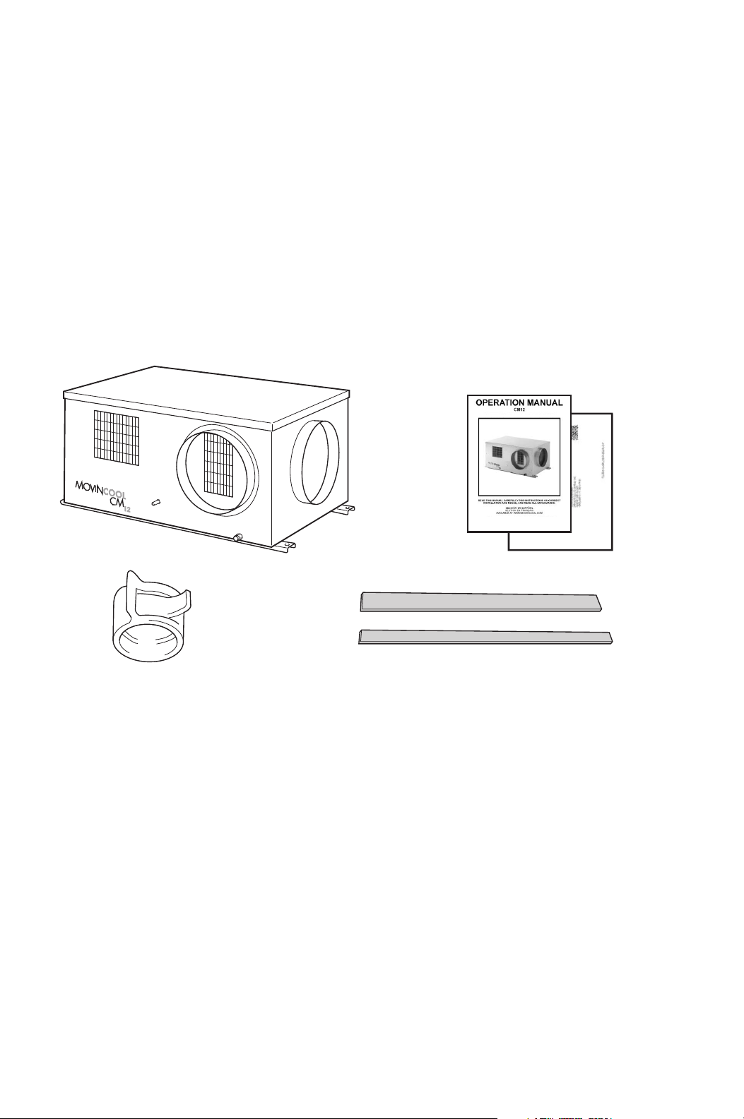
INVENTORY
CM12 UNIT OPERATION MANUAL /
PRODUCT REGISTRATION
CLIP
PACKING I (2.8 in x 32.0 in x 0.2 in)
PACKING II (1.0 in x 33.0 in x 0.2 in)
After unpacking your MovinCool unit, please check to make sure you have the
following items:
1. CM12 MovinCool Unit (1)
2. Operation Manual/Product Registration (1)
3. Clip (1)
4. Packing I (1)
5. Packing II (1)
Note: If any of these items were not included in the box or appear damaged,
please contact your MovinCool reseller for replacement.
6
Page 7
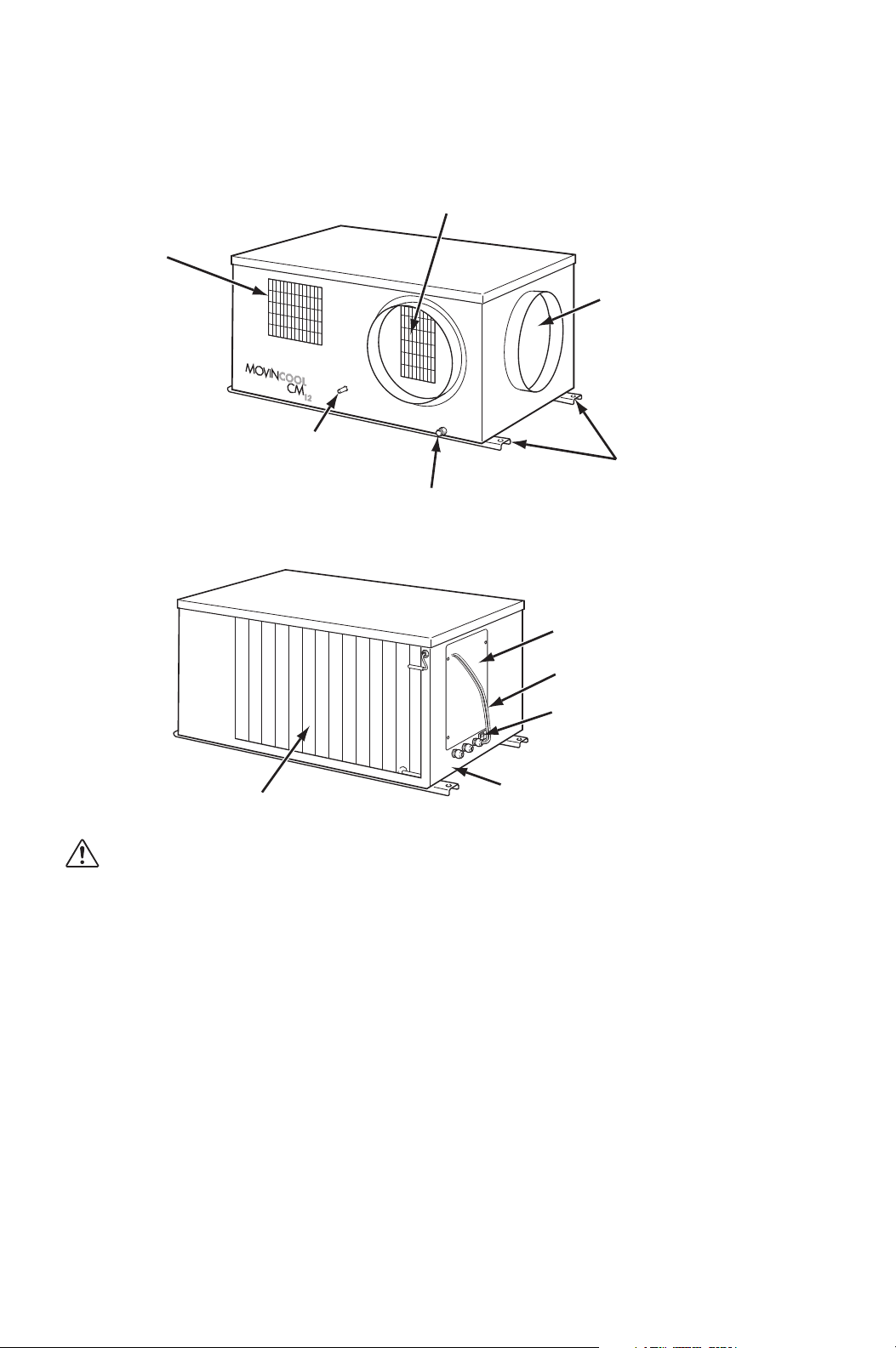
INSTALLATION
COLD AIR EXHAUST (10.0 in DIA. FLANGE)
DRAIN PIPE
FOR PUMP
CONDENSER (HOT)
AIR EXHAUST
EVAPORATOR (ROOM)
AIR INTAKE
(10.0 in DIA. FLANGE)
MOUNTING
BRACKETS
CONDENSATE PAN
DRAIN FOR MAINTENANCE
SERVICE PANEL
OVERRIDE (STOP)
SWITCH
POWER CORD
CONNECTION
CONDENSER AIR INTAKE
SIGNAL WIRE
Unit Overview
WARNING: Remove protective cardboard from condenser intake
after installation.
7
Page 8
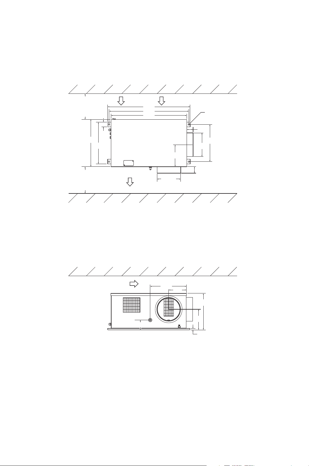
INSTALLATION (cont.)
WALL
All dimensions are in inches.
Unit Weight: 123 lb (56 kg)
WALL
CEILING
INTAKE
EXHAUST
Minimum
clearance
40.0 in
from wall
Minimum
clearance
40.0 in
from wall
Ø0.6
Ø10.0
15.3
7.5
15.8
4.1
8.7
17.6
19.9
34.8
33.6
32.0
15.7
2.7
2.8
0.6
Top of the unit should not contact
any building structure or object.
2.0
10.0
9.2
Clearance Requirement
8
Page 9

INSTALLATION (cont.)
1/2 in THREADED ROD
(MIN. 123 lb (56 kg) LOAD CAPACITY)
SEE MOUNTING DETAIL
VIBRATION ISOLATOR
(MIN. 123 lb (56 kg) LOAD CAPACITY)
1/2 in THREADED ROD
(MIN. 123 lb (56 kg)
LOAD CAPACITY)
1/2 in NUT
1/2 in WASHER
MOUNTING BRACKET
1/2 in WASHER
1/2 in NUT
1/2 in JAM NUT
Mounting the CM12 to a Roof Structure
WARNING: Be sure that the supporting roof structure is capable of
supporting the weight of the unit, mounting hardware and the
accessories (Roof structure should be capable to support four
times of total weight or more. Unit weight is 123 lb (56 kg).
Be sure to securely anchor the top ends of the suspension rods. Make sure all nuts
are tight. Be sure to follow all applicable codes.
The CM12 unit is usually mounted above the ceiling and must be securely
mounted to the roof structure. The ceiling support of the existing building may
require reinforcements.
Use field-supplied threaded 1/2 inch suspension rods, washers, nuts and vibration
isolators.
The recommended clearance between ceiling grids and building the structural
member is the unit height plus 3.0 inch (76 mm).
ALL MOUNTING HARDWARE FIELD PROVIDED
Install the four field-supplied rods by
suspending them from suitable
building structure members. Locate
the rods so that they will align with
four mounting holes in the mounting
bracket that are part of the unit
base.
WARNING: Wear gloves to
Tightening torque for nuts: 3.02
avoid injury during
installation.
ft•lbf (4.1 N•m)
CAUTION: Make sure the
unit is level (must be less
than 2° incline).
9
Page 10

INSTALLATION (cont.)
CIRCUIT BREAKER WITH
GROUND-FAULT PROTECTIVE
FUSE 20 A MAX.
RTG
RTG
TERMINAL BLOCK OF CM12
GROUND TERMINAL
Power Supply Requirements
• The CM12 requires a single-phase 115 V, 60 Hz power supply to operate.
• The power supply should be a dedicated single outlet circuit with a UL approved
short-circuit and ground fault protective breaker with a fuse size of 20 A maximum.
Service Panel Access
1. Access service panel by
removing 4 screws.
Tightening torque for screw: 1.10
ft•lbf (1.5 N•m)
2. Remove the service panel.
10
Page 11

INSTALLATION (cont.)
POWER CORD
DRAIN PIPE
CONDENSATE PAN
DRAIN FOR MAINTENANCE
Power Connection
Connecting Power Supply to Unit
The following are recommended wire sizes
and electrical ratings:
• Cord Type: SJT (3 wires) or
equivalent
• Wire Gauge: 14 AWG
• Voltage Rating: 300 V minimum
• Heat Resistance: 140 °F (60 °C)
1. Remove service panel from the right
side of CM12 unit.
2. Route power cord wires through the
opening of the left grommet connector located below service panel. Tighten
the grommet connector at about 0.15 ft•lbf (0.2 N•m) torque.
3. Connect the neutral wire (white color label “R”) to the center screw connection
of terminal block. Tighten screw at about 0.96 ft•lbf (1.3 N•m) torque.
T
G
R
4. Connect the line wire (black color label “T”) to the left screw connection of
terminal block. Tighten screw at about 0.96 ft•lbf (1.3 N•m) torque.
5. Connect the ground wire (green color label “G”) to brass screw located below
terminal block. Tighten screw at about 0.96 ft•lbf (1.3 N•m) torque.
WARNING: All electrical work, if necessary, should only be
performed by qualified personnel. Repair to electrical components
by non-certified technicians may result in personal injury and/or
damage to the unit.
Drain Hose Connection
The CM12 is equipped with an internal
condensation removal pump. Maximum lift
is 4 feet (1.2 m).
1. Use the provided 1/2 inch (13 mm)
female connection on the unit for the
evaporator coil condensate drain. The
drain line must be located so it will not
be exposed to freezing temperatures.
The drain should be the full size of the
drain connection. (Connect the drain
hose to the condensation drain or the janitor closet.)
2. A 1/2 inch (13 mm) ID (5/8 inch (16 mm) OD), PVC tubing is required for the
drain. Insulate the drain hose; condensation may occur during humid
conditions. (Field supplied material)
11
Page 12

INSTALLATION (cont.)
RED STOPPER
MAX. 3 ft
(0.9 m)
MAX. 4 ft (1.2 m)
1/4 inch (6 mm)
PER FOOT
OR MORE
Drain Hose Connection (cont.)
1. Plug in the 1/2 inch (13
mm) drain hose with the
lose clip into the drain
pipe. Make sure the hose
is all the way in and flush
with the grommet.
2. Position the clip to the top
of the drain pipe near the
unit as shown.
3. Pull out the red stopper and
secure hose. Make sure
there are no kinks or bends.
When using the gravity
drain, make sure the hose
is connected as a decline.
Note: Do not use more than 4 feet (1.2 m) of drain hose vertically. This is maximum
lift of the condensation pump.
To insure proper drainage, locate the drain hose to the highest vertical position, no
more than 4 feet (1.2 m) high, and run the hose to the drain, run the drain hose on
a downward slope at a minimum rate of 1/4 inch (6 mm) per foot.
Check following items:
1. No kinks or bends on the drain hose
2. No trap in the drain hose
3. The end of the drain hose should be highter than the water level at the drain
4. No dripping from the drain hose at the clamping area
DRAIN HOSE ARRANGEMENT
SLOPE
ABOVE
DRAIN
CM12
NO TRAP
TO DRAIN HOSE
When uninstalling the unit, empty the drain pan by draining out the water through
the drain pan drain pipe.
WATER
12
CM12
NO TRAP
NO POOL
Page 13

INSTALLATION (cont.)
Wall Thermostat
Connector Name
CM12 WIRES
Label Name Color
Function
RC
Y
G
G1
RC
Y
G
G1
Brown
Red
Orange
Yellow
Common
Cool On/Off
Fan On/Off
Fan Hi/Lo
Packing Attachment
Apply include “Packing I” (provided) and
“Packing II” (provided) to the cold air outlet
flange to prevent condensation in high
humidity environments.
1. Release the liner on Packing I and
apply to outside flange cylinder of the
ring as shown.
2. Release the liner on Packing II and
apply to edge of Packing II as shown.
PACKING I
PACKING II
Wall Thermostat Connection (Millivolt System ONLY)
Preparation for Wall Thermostat Connection
1. Use with a single stage wall thermostat.
Thermostat type: Millivolt System
2. Set the wall thermostat to cooling system mode, since most wall thermostats
are designed for both heating and cooling.
3. Prepare the wire harness for connection from the unit to the thermostat. The
recommended wire size is:
Wire Type: Thermostat cable / Solid wire 16 ~ 26 AWG
4. Identify the thermostat connectors labeled G, G1, Y, and RC.
G (Fan On/Off), G1 (Fan Speed Hi/Lo), Y (Cooling On/Off) and RC (Cooling
Transfer - Common)
Connecting Thermostat to CM12 Unit
13
Page 14

INSTALLATION (cont.)
CM12 UnitThermostat
(Millivolt System)
Orange Wire
G
Y
RC
G1
Red Wire
GYWRCRHOB
Brown Wire
Yellow Wire
Remove Factory-Installed Jumper
Use only with thermostat that has
Fan Hi-Lo Speed control.
Note: Use thermostat that is compatible with millivolt system. Do not connect
thermostat to AC power source.
5. Install the wall thermostat to the proper location inside the room where it can
be conveniently accessed. Do not install the wall thermostat where unusual
heating condition may occur (i.e. hot stove, hot pipe, fireplace, direct sunlight,
and etc.)
Most thermostats provide these basic functions:
Fan Mode: On / Auto (Select the desired fan mode)
System: Cool / Heater (Select Cool only)
Warning Signal Connection (Output Signal)
The CM12’s controller is equipped with a warning signal output relay type (FormC, normal open dry contact), which can be used to monitor the failure condition.
Relay contactor is closed when the following condition has occurred:
a. Condensation Overflow
b. Temperature Sensor fails
c. Cooling Function fails
The relay output contactor is rated 5 A at 30 VDC or 5 A at 250 VAC (resistive
load), and it is compatable with various warning devices such as alarm speakers,
light indicators, and etc.
Connecting Warning Signal From CM12
1. Connect the warning device to CM12 signal wires label L+ and L-.
2. Use recommended warning signal wire size from 16 AWG to 26 AWG for a
solid wire, or 16 AWG to 22 AWG for a stranded wire.
14
Page 15

INSTALLATION (cont.)
1234
NO
“OFF” POSITION
250V 5A
OUTPUT: 12.6V-0.37A
GA09301-G ST
INPUT: 230V 115V 0
CN01
CN15CN16CN14CN02CN03CN04
CN17
CN25
CN23 CN22 CN21
4
3
52CH
RTSCTSODS
SW2
4-POSITION DIP SWITCH
Fire Alarm Control Panel Connection (Input Signal)
The CM12’s controller is equipped with a normal open input signal, which can be
connected directly from the fire alarm control panel. When receiving the signal
from the fire alarm control panel, the unit turns off and does not turn back on until
power source is reset or turns the wall thermostat off and on.
Connecting Fire Alarm Control Panel to CM12
1. Connect the fire alarm signal wires to CM12 signal wires label E+ and E-.
2. Use recommended fire alarm signal wire size from 16 AWG to 26 AWG for a
solid wire, or 16 AWG to 22 AWG for a stranded wire.
DIP Switch Configuration and Setting
The CM12’s controller is equipped with a 4-position DIP switch, which defaults in
the OFF position. The DIP switch can be set to configure the following functions:
a. When the switch position #1 is ON, the evaporator and condenser fan
motor turn on. This function is used for test purposes and verification.
b. When switch position #2 is ON, the compressor, evaporator and condenser
fan motor turn on. This function is used for test purposes and verification.
c. When switch position #3 is ON, the compressor delay timer function is
disabled.
15
d. When switch position #4 is ON, the buzzer sound function is disabled.
Page 16

INSTALLATION (cont.)
Ducting With Typical Drop Ceiling
RETURN GRILL WITH FILTER REQUIRED
CONDENSER
INTAKE
CONDENSER
EXHAUST
2 ft x 2 ft,
T-bar diffuser
with 10.0 in flange
COOL AIR SUPPLY
(EVAPORATOR)
10.0 in insulated
flexible duct
(6 ~ 10 ft each)
2 ft x 2 ft,
T-bar return
grill with 10.0 in
flange and filter
ROOM AIR
INTAKE
Use a 10.0 inch diameter insulated duct with low friction and air resistance.
The duct should be bent in a large radius. If the bending radius is less than 15.0
inch (381 mm), then use vanes or guides to reduce air resistance.
Make sure the ducts are secured in order to absorb vibration from the unit.
Avoid bending the duct suddenly and have air ducts travel in a strait line for
improved performance.
• Following filed supplied hardware requires:
• Insulated 10.0 inch diameter ducts
• Return air grill with filter for evaporator air intake
• Diffuser for cold air
• Maximum external static pressure, 0.40 IWG (100 Pa) for evaporator duct and
grills
CAUTION: Do not operate CM12 without the filter installed on the
return air grill.
16
Page 17

FEATURES
CM12 Features
• Built-in condensation removal pump
• Built-in mounting bracket
• Built-in flange for supply and return air (room air) - 10.0 inch diameter, 2.8 inch
deep cylinder for easy installation
• Fire alarm control panel connection with automatic shut off
• Automatic shut off and warning signal output and alarm for
• Condensation Overflow
• Unit Failure (no cooling)
• Temperature Sensor Failure
INSPECTION & MAINTENANCE
Cleaning Air Filters
The air filter on the evaporator return grill should be checked weekly for dust
buildup.
Clean or replace air filter on a weekly basis. If the unit is used in a dusty
environment, more frequent cleaning may be required.
A dirty air filter can reduce the air output, resulting in a decrease in cooling
capacity.
Cleaning Condenser Air Intake
Inspect and remove dust buildup on the condenser air intake of the unit with a
vacuum cleaner periodically to prevent insufficient cooling.
Ground Fault Breaker Testing
The ground fault breaker should be tested at least once a month.
17
Page 18

TROUBLESHOOTING
PATTERN 1
(Internal thermistor failure)
PATTERN 4
(Fire alarm signal input)
PATTERN 2
(Pump or drain problem)
PATTERN 3
(Refrigeration system
problem)
ON
OFF
ON
OFF
ON
ON
OFF
0.5 sec
0.5 sec
0.5 sec
4 sec
4 sec
1 sec
Buzzer Pattern
18
Page 19

TROUBLESHOOTING (cont.)
Check the following items before calling your MovinCool reseller or a qualified
technician.
CONDITION POSSIBLE CAUSE REMEDY
Unit does not
operate
Insufficient Cooling /
Unit operation
interrumpted
frequently.
1. Power supply is off Check circuit breaker.
2. Power interruption Unit will turn on automatically
when power back (Some
thermostats require reset).
3. Blockage of air duct Check duct for any blockages or
excessive kinks in ducting.
4. Turn off signal input Check for turn off signal input (fire
alarm control panel).
5. Override (Stop) switch is
active
6. Battery ran out on
thermostat
1. Blockage of Condenser air
intake or outlet in the ceiling
2. Dirty Surface of Condenser
Core
3. Dirty / Blocked filters Clean / replace air filter.
4. Excessive evaporator air
ducting
Ensure the switch is in
“OPERATE” position.
Change battery.
Check any blockages in the
ceiling.
Clean surface of Condenser Core.
Evaporator ducting should not
exceed 10 feet (3.0 m) and bend
radius should be larger than twice
of duct diameter.
Beeping / Alarm
coming from unit and
unit stops.
(Buzzer sound
pattern indicated on
page 18.)
5. Blockage of Condenser air
intake or outlet in the ceiling
6. Outside of operating range Use within operating temperature
1. Internal thermistor failure
(Sound pattern 1)
2. Pump or drain problem
(Sound pattern 2)
3. Refrigeration system
problem (Sound pattern 3)
4. Receiving fire alarm signal
input (Sound pattern 4)
Remove the blockage.
range.
Replace internal thermistor.
Check for drain connection and
blockage, kink or bend on drain
hose. (See “Drain Hose
Connection” on page 11.)
Turn off power source and contact
your MovinCool reseller or a
qualified technician.
Reset power source or turn the
wall thermostat off and on.
If conditions persist after the above actions have been taken, turn the unit off,
disconnect the power and contact your MovinCool reseller or a qualified technician.
19
Page 20

TROUBLESHOOTING (cont.)
CM12: Installation Check Sheet
ITEMS
Installation Unit Check and make sure all screws are tight and
unit is secured in place.
Check and make sure inlet / outlet air exhaust
are clear without blockage.
Wiring Check and make sure the unit is properly
connected to the dedicated circuit breaker.
Check and make sure all wiring are properly
connected and secured.
Check and make sure ground wire is tighten
and secured.
DIP Switch Setting Check and make sure all DIP switches
located on relay board are set to “OFF”
positions.
Before Test
Operation
Test
Operation
Drain Hose
Connection
Grill Installation Check and make sure that grill is secured and
Wall Thermostat Check and make sure wall thermostat is
Other Remove card board on condenser inlet side.
Maintenance Switch Check and make sure override switch located
Check Operation
with Wall
Thermostat
Abnormal Noise Check and observe abnormal noise during
Check and make sure that drain hose
provided with heat insulator to prevent
condensation on hose surface.
properly installed.
connected properly to unit.
below maintenance’s panel is at “OPERATE”
position before test operation.
Set wall termostat to Fan On or Fan Only
mode to confirm fan only mode operation.
Set wall thermostat to Fan Auto or Cool mode
operation. During cool mode operation, check
and cinfirm cooling operation after delay timer
is expired. (Note: Delay timer vary from 2 ~ 5
min depending on thermostat model used.)
Blowing/Cooling operation.
Drain During cooling operation, check and observe
condensation drip through normal drainage
path.
Air Leakage Check for air leakage from duct and duct
connection.
20
Page 21

TECHNICAL SPECIFICATIONS
ITEM SPECIFICATIONS
Electronic Features Control Millivolt Thermostat
(Field supplied)
Electrical Characteristics Voltage Requirement Single-Phase, 115 V, 60 Hz
Operating
Voltage Range
Max. 127 V
Min. 104 V
Recommended Fuse Size 15 A
Cooling Capacity and Power Consumption
*1
*1
*1
*1
10,500 Btu/h (3,090 W)
7,200 Btu/h (2,100 W)
1.23 kW
11.2 A
Evaporator: 80 °F (27 °C),
50 %RH
Condenser: 95 °F (35 °C),
50 %RH
Total Cooling Capacity
Sensible Cooling Capacity
Power Consumption
Current Consumption
EER 8.5
*1
*1
*1
*1
9,300 Btu/h (2,730 W)
7,000 Btu/h (2,040 W)
1.22 kW
11.1 A
Evaporator: 72 °F (22 °C),
50 %RH
Condenser: 95 °F (35 °C),
50 %RH
Total Cooling Capacity
Sensible Cooling Capacity
Power Consumption
Current Consumption
EER 7.6
Compressor Type of Compressor Hermetic Rotary
Evaporator Type of Fan Centrifugal Fan
Air Flow High
Low
324 CFM (550 m
228 CFM (390 m
Max. External Static Pressure 0.16 IWG (40 Pa)
3
3
/h)
/h)
Condenser Type of Fan Centrifugal Fan
Air Flow
High
Low
700 CFM (1,190 m
370 CFM (630 m
Max. External Static Pressure 0.12 IWG (30 Pa)
Refrigerant Type R-410A
Amount 1.59 lb (0.72 kg)
Dimension W x D x H Without Flange
and Mounting
Bracket
With Flange
and Mounting
Bracket
32.0 x 19.9 x 15.2 in
(813 x 505 x 386 mm)
34.8 x 22.7 x 15.8 in
(884 x 577 x 401 mm)
Weight Net 123 lb (56 kg)
21
3
3
/h)
/h)
Page 22

TECHNICAL SPECIFICATIONS (cont.)
ITEM SPECIFICATIONS
Condensate Pump
Capacity
Operating Condition
Range
Maximum Duct Length
Maximum Sound Level
*2
Pump Rate 5.0 gal/h (19 L/h)
Max. Head 4 ft (1.2 m)
Evaporator Air
Inlet
Condenser Air
Inlet
*3
Cold Duct 20 ft (6.1 m)
Hot Duct 10 ft (3.0 m)
*4
High 52 dB (A)
Low 52 dB (A)
Max. 95 °F (35 °C), 50 %RH
Min. 65 °F (18 °C), 50 %RH
Max. 113 °F (45 °C), 50 %RH
Min. 65 °F (18 °C), 50 %RH
• Specifications are subject to change without notice.
Note:
*1: With two 6-foot (1.8 m) ducts containing one 90° bend each, supply grill and
return grill with filter [0.16 IWG (40 Pa) external static pressure] on high fan
speed.
*2: When ambient temperature is lower than 65 °F (18 °C), operation may be
interrupted due to anti-freeze protection activation.
*3: Confirm pressure drop of duct, grills, and filter with manufacture’s
specifications.
*4: Measured at 3 feet (1.0 m) under the ceiling with evaporator duct and ceiling
tile.
22
Page 23

WARRANTY STATEMENT
DENSO PRODUCTS AND SERVICES AMERICAS, INC. ("DENSO") warrants its
MOVINCOOL Products only to the extent stated in its official written warranties. Unless
otherwise specifically provided in writing by DENSO, DENSO warrants to the original end-user
that the products shall be free of defects in materials or workmanship and will function in
accordance with DENSO's published specifications under ordinary intended use and service
for a period listed below beginning from the date of purchase on the invoice to the end-user:
CM12 Warranty: 2 Years on the Unit and 3 Years on the Compressor with warranty registration
OR 1 Year on the Unit and 3 Years on the Compressor for unregistered units.
DENSO shall, at its sole discretion, repair or replace any defective product covered by this
warranty. Such remedy shall be end-user's sole remedy with respect to any particular defect
in the products.
This warranty does not cover defects or malfunctions which result from causes beyond
DENSO's control, including, without limitation, (i) unusual physical or electrical stress; (ii)
accident, neglect, abuse, misuse or other abnormal use; (iii) failure to perform routine
maintenance in accordance with DENSO's recommended procedures; (iv) normal wear and
tear; (v) repairs or attempted repairs by an unauthorized person; (vi) modifications or
alterations to the products; (vii) use with parts or devices not supplied or approved by
DENSO; (viii) improper installation or service; (ix) shipping damage to any units or spare
parts during shipping. This includes and is not limited to compressors, evaporators and
condenser coils. This warranty shall extend only to the original end-user and shall be void if
any labels or other identifying marks permanently affixed to products when shipped by
DENSO are removed, altered, defaced or obliterated.
TO THE EXTENT PERMITTED BY LAW, THIS WARRANTY, AS LIMITED HEREIN, SHALL
BE IN LIEU OF AND EXCLUSIVE OF ALL OTHER WARRANTIES, EITHER EXPRESSED
OR IMPLIED, ON THE PART OF DENSO PRODUCTS AND SERVICES AMERICAS, INC.,
OR DENSO CORPORATION, WHETHER ARISING FROM LAW, COURSE OF DEALING,
USAGE OF TRADE, OR OTHERWISE, INCLUDING WITHOUT LIMITATION ANY
IMPLIED WARRANTY OF MERCHANTABILITY OR FITNESS OF A PARTICULAR
PURPOSE OR ANY LIABILITY FOR COMMERCIAL LOSSES BASED UPON
NEGLIGENCE OR MANUFACTURER'S STRICT LIABILITY. EXCEPT AS EXPRESSLY
PROVIDED HEREIN, NEITHER DENSO PRODUCTS AND SERVICES AMERICAS, INC.,
NOR DENSO CORPORATION WILL, IN ANY EVENT, BE LIABLE FOR LOST PROFITS,
COSTS OF PROCESSING, INJURY, GOODWILL, OR ANY OTHER CONSEQUENTIAL
DAMAGES OF ANY KIND ARISING FROM BREACH OF THIS WARRANTY.
DENSO PRODUCTS AND SERVICES AMERICAS, INC. reserves the right to make
changes without prior notice. MovinCool®, Office Pro® and SpotCool® are registered
trademarks of DENSO Corporation.
PURCHASE DATE:
SERIAL NUMBER:
Page 24

P/N: 484007-3433EN Fourth Issue: March 2015
 Loading...