

Page 1
SPARE PARTS CATALOG
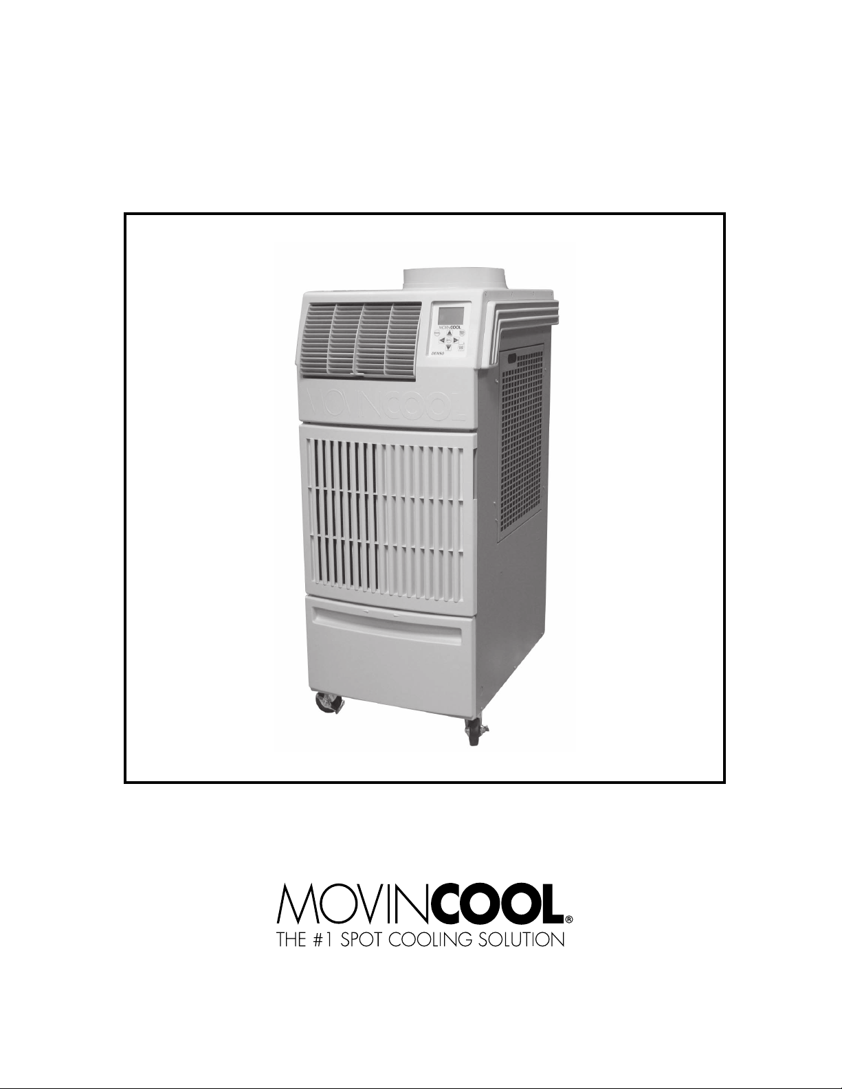
CLIMATE PRO 18
DocID:00G00094E
Page 2
Table of Contents
Nameplate Label Position
Nameplate Label
COOLING AMPS. WITH PUMP
COMPR. OUTPUT
REFRIGERANT/TOTAL CHARGE
DESIGN PRESSURE LO/HI
PART NO./WEIGHT
SERIAL NO.
Month
Model
Sequential
Number
Year
▲▲ XXXX ###
No.
1 GX484000-4490
UNIT PART
NUMBER
SERIAL NUMBER RANGE REFRIGERANT SECTION
0914XXXXH18 to Present
(From September 2014 to Present)
R410A
Page 3 ~ 13
SP0081-00
SERIAL NUMBER LOCATION AND IDENTIFICATION
© 2014 DENSO PRODUCTS AND SERVICES AMERICAS, INC.
All rights reserved. This book may not be reproduced or copied, in whole or in part, without the
written permission of the publisher. DENSO PRODUCTS AND SERVICES AMERICAS, INC.
reserves the right to make changes without prior notice. MovinCool®, Office Pro® and
SpotCool® are registered trademarks of DENSO Corporation.
Page 3

No.1 SP0081-00
CLIMATE PRO 18
Unit Part No: GX484000-4490
Unit Serial Number Range:
0914XXXXH18 to Present
(From September 2014 to Present)
3
Page 4
Unit Serial Number Range: 0914XXXXH18 to Present
CLIMATE PRO 18
30-3
30-4
15
17
30
43
30-1
30-2
28-4
29
28-2
28-5
32
28-3
28-1
28
22
33-1
20
33-3
38-7
38-1
38-2
21
21-1
38-4
15
38-3
37
37-2
37-1
38-6
38-5
38
15
33
33-2
31
41
15,42
39
16
17
12
19
25
15
13
2
10
11
7
5
3
24
23
39-1
6
40
26
27
15
18
14
9
15
36
34-4
35
4
8
1
3
31
17
34-2
34
34-1
34-3
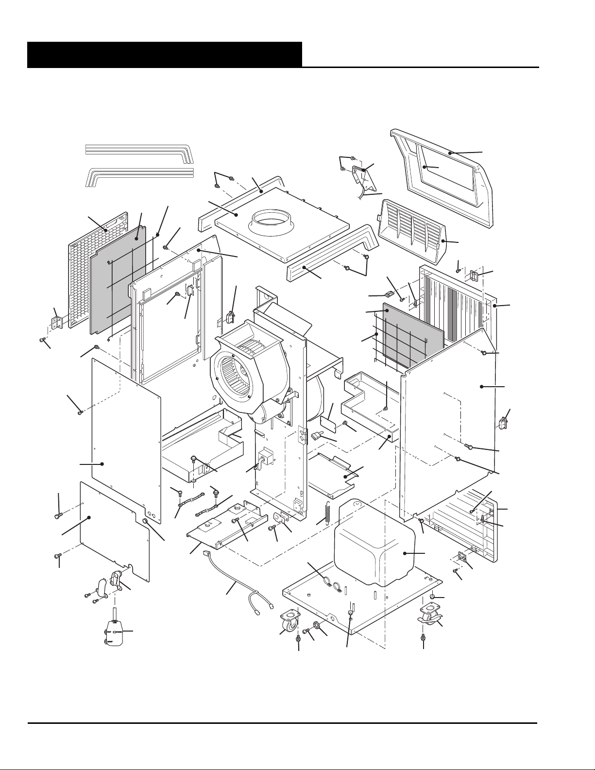
ILL00845-00
4SP0081-00
Page 5

Unit Serial Number Range: 0914XXXXH18 to Present
CLIMATE PRO 18
ILL.
NO.
DESCRIPTION PART NO. QTY.
UNIT
SERIAL NO.
REMARKS
RANGE*
1 Caster w/Brake LA484702-0330 2
2 Caster w/No Brake LA484702-0340 2
3 Bolt w/Washer 91510-08141 8 M8×1.25, L=14
4 Washer, Plate 90201-06400 1 For Ground Screw
5 Ground Screw 90051-06120 1 M6×1, L=12
6 Clamp LA484506-0090 1 For LCDI Power Cord, w/Screws
7 Clamp 465574-0170 2
8 Nut 949056-1501 3 M4×0.7
9 Frame Sub-Assy LA484310-3600 1 For Drain Tank
10 Spring, Tension Coil 484917-0680 2 For Drain Tank
11 Drain Tank Switch LA484502-0380 1 (DS)
12 Wire Assy 481950-2270 1 For Drain Tank Switch
13 Screw w/Washer 91310-03161 2 M3×0.5, L=16
14 Drain Pan Assy, Indoor LA484430-0120 1
15 Screw GX949006-5850 49 M4×0.7, L=10
16 Drain Pan Assy, Outdoor GX484430-0800 1 w/Heater
17 Screw, Tapping 482801-2920 7 D=4, L=12 for Plastic Bush
18 Jumper Plug LA484930-8160 1 For Optional Condensate Pump
19 Wire Assy 481950-2260 1 For Optional Condensate Pump
20 Plate LA484311-2880 1 Cover for Condensate Pump Wire
21 Switch Assy GX484560-2430 1 Operation Panel & PCB
w/ILL.No.21-1
21-1 Wire Assy GX481950-2300 1 (RB)↔(CB), Main Wire Harness
22 Screw GX949006-5850 4 M4×0.7, L=10
23 Wire Assy, Ground 481950-2280 1 L=1100
24 Screw, Ground 91051-04100 4 M4×0.7, L=10
25 Wire Assy, Ground 481950-2290 1 L=160
26 Screw w/Washer 91370-06121 1 M6×1, L=12
27 Stay Sub-Assy GX484340-3690 1 Divider Panel for Outdoor
Heat Exchanger
28 Panel Assy, Right GX484470-5040 1 w/ILL.No.28-1~28-5
28-1 Right Handle LA484450-0051 1
28-2 Holder 484927-0990 2 Magnet Type
28-3 Catch LA481922-0030 2 Door Hook
28-4 Screw 949006-4440 4 M3×0.5, L=8
28-5 Screw, Tapping 949001-3530 6 D=4, L=10
29 Bolt w/Washer 91370-06141 4 For Panel Assy Right,
M6×1, L=14
*: Please refer to page number 2 for the position of the nameplate showing the serial number on the unit.
"Unit Serial Number Range*" column indicates the first four digits of the unit serial number.
5 SP0081-00
Page 6

Unit Serial Number Range: 0914XXXXH18 to Present
CLIMATE PRO 18
30-3
30-4
15
17
30
43
30-1
30-2
28-4
29
28-2
28-5
32
28-3
28-1
28
22
33-1
20
33-3
38-7
38-1
38-2
21
21-1
38-4
15
38-3
37
37-2
37-1
38-6
38-5
38
15
33
33-2
31
41
15,42
39
16
17
12
19
25
15
13
2
10
11
7
5
3
24
23
39-1
6
40
26
27
15
18
14
9
15
36
34-4
35
4
8
1
3
31
17
34-2
34
34-1
34-3
ILL00845-00
6SP0081-00
Page 7

Unit Serial Number Range: 0914XXXXH18 to Present
CLIMATE PRO 18
ILL.
NO.
DESCRIPTION PART NO. QTY.
UNIT
SERIAL NO.
REMARKS
RANGE*
30 Panel Sub-Assy, Right GX484490-0230 1 w/ILL.30-1~30-4
30-1 Filter, Outdoor GX484401-2060 1
30-2 Wire Frame GX484310-6620 1
30-3 Hinge GX484912-0180 2
30-4 Screw 949006-3300 4 For Hinge, M3×0.5, L=6
31 Bolt 480919-0370 15 M4×0.7, L=10
32 Panel Assy, Top GX484490-0240 1
33 Panel Assy, Left GX484490-0250 1 w/ILL.No.33-1~33-3
33-1 Left Handle LA484450-0061 1
33-2 Catch LA481922-0030 1
33-3 Screw, Tapping 949001-3530 6 D=4, L=10
34 Panel Assy, Drain Tank Door LA484410-5031 1 w/ILL.No.34-1~34-4
34-1 Door Hook LA484927-1010 2
34-2 Screw, Tapping LA949001-1730 4 For Door Hook, D=4, L=16
34-3 Hinge GX484912-0180 2
34-4 Screw 949006-3300 4 For Hinge, M3×0.5, L=6
35 Nut 91160-03241 4 M3×0.5
36 Drain Tank 484731-0220 1
37 Panel Assy, Upper Front GX484490-0300 1 w/ILL.No.37-1~37-2
37-1 Louver, Air Outlet LA480431-0101 1
37-2 Pin LA484913-0070 3
38 Panel Assy, Lower Front LAY84410-0021 1 w/ILL.No.38-1~38-7
38-1 Filter, Indoor LA484401-1160 1
38-2 Wire Frame LAY84310-0020 1
38-3 Door Hook LA484927-1010 1
38-4 Screw, Tapping LA949001-1730 2 For Door Hook, D=4, L=16
38-5 Hinge GX484912-0180 2
38-6 Screw 949006-3300 4 For Hinge, M3×0.5, L=6
38-7 Clip LAY84917-0051 2 For Wire Frame
39 Panel Assy, Rear GX484490-0260 1 w/ILL.No.39-1
39-1 Grommet GX484926-0700 2 D=19.1, For Signal Device/
External Thermostat Wire
40 Wire Assy, LCDI Power Cord LA484930-8680 1
41 Service Panel GX484490-0270 1
42 Washer, Toothed 949016-0230 3 For Service Panel
43 Stripe Kit Assy LA484003-1110 1 Sticker for Left & Right Handles
*: Please refer to page number 2 for the position of the nameplate showing the serial number on the unit.
"Unit Serial Number Range*" column indicates the first four digits of the unit serial number.
7 SP0081-00
Page 8

Unit Serial Number Range: 0914XXXXH18 to Present
CLIMATE PRO 18
5
8
8
5-1-1
5-1
5-2
7
5-1-2
6
5-2-1
9
4
4-1
4-2
9
1-3
1-4
1-2
1-1
3
2
1
9
10
ILL00846-00
8SP0081-00
Page 9

Unit Serial Number Range: 0914XXXXH18 to Present
CLIMATE PRO 18
ILL.
DESCRIPTION PART NO. QTY.
NO.
1 Compressor Assy GX484650-3340 1 w/Pipe for Discharge & Suction
1-1 Wire Assy 481950-2200 1 For Compressor
1-2 Overload Relay GX484501-0410 1
1-3 Cushion GX484904-0380 3
1-4 Collar GX484915-0410 3
2 Washer, Steel Plate 949011-5330 3
3 Nut 90190-08651 3 M8×1.25
4 Indoor Heat Exchanger Assy GX484600-2940 1 w/ILL.No.4-1~4-2
4-1 Pipe Assy GX484800-5592 1
4-2 Distributor Assy GX484620-0160 1
5 Outdoor Heat Exchanger Assy GX484600-2950 1 w/ILL.No.5-1~5-2-1
5-1 Pipe Assy GX484800-5620 1 w/ILL.No.5-1-1~5-1-2
5-1-1 4 Way Valve GX484782-0290 1
5-1-2 High Pressure Switch GX484660-0660 1 (HPRS)
5-2 Pipe Assy GX484800-5630 1 w/ILL.No.5-2-1
5-2-1 Expansion Valve 484602-0110 1
6 Controller Assy 484500-4470 1 For Expansion Valve
7 Controller Assy GX484500-4510 1 For 4 Way Valve
8 Thermistor Assy 482780-1540 2 (ODS, CTS3)
9 Thermistor Assy 482780-0960 3 (RTS, CTS1, CTS2)
10 Pipe Assy, Charging 484800-0440 1 5 Pieces Per Package
UNIT
SERIAL NO.
RANGE*
REMARKS
w/ILL.No.1-1~1-4
*: Please refer to page number 2 for the position of the nameplate showing the serial number on the unit.
"Unit Serial Number Range*" column indicates the first four digits of the unit serial number.
9 SP0081-00
Page 10

Unit Serial Number Range: 0914XXXXH18 to Present
CLIMATE PRO 18
11
9
14
14-1
12
10
4
8
7
6
4
5
4
9
9
9
13
9
9
2
1
4
3
4
ILL00847-00
10SP0081-00
Page 11

Unit Serial Number Range: 0914XXXXH18 to Present
CLIMATE PRO 18
ILL.
DESCRIPTION PART NO. QTY.
NO.
1 Stay Sub-Assy, Indoor Fan Motor GX484340-3670 1 Mounting Plate
2 Motor, Indoor Fan GX484211-2130 1
3 Fan, Indoor LA484221-0360 1 w/Set Screw
4 Nut GX949056-1430 16 M6×1
5 Stay Sub-Assy, Outdoor Fan Casing GX484340-3680 1 Mounting Plate
6 Motor, Outdoor Fan GX484211-2140 1
7 Fan, Outdoor GX484221-0800 1 w/Set Screw
8 Casing Sub-Assy, Outdoor Fan GX480420-0130 1
9 Screw GX949006-5850 16 M4×0.7, L=10
10 Ring, Outdoor Inlet GX484381-0920 1
11 Stay, Control Panel Right GX481821-2560 1
12 Stay, Control Panel Left GX481821-2571 1
13 Stay GX481821-2580 1
14 Switch Assy GX484560-2430 1 Operation Panel & PCB
14-1 Wire Assy GX481950-2300 1 (RB)↔(CB), Main Wire Harness
UNIT
SERIAL NO.
RANGE*
REMARKS
w/ILL.No.14-1
*: Please refer to page number 2 for the position of the nameplate showing the serial number on the unit.
"Unit Serial Number Range*" column indicates the first four digits of the unit serial number.
11 SP0081-00
Page 12

Unit Serial Number Range: 0914XXXXH18 to Present
CLIMATE PRO 18
1
8
6
7
4
5
6
3
14
16
15
28
6
4
5
2-1
2
10
10
17
6
11
252627
12
11
9
13
22
22
20
22
21
18
19
23
24
ILL00848-00
12SP0081-00
Page 13

Unit Serial Number Range: 0914XXXXH18 to Present
CLIMATE PRO 18
ILL.
NO.
DESCRIPTION PART NO. QTY.
UNIT
SERIAL NO.
REMARKS
RANGE*
1 Service Box GX484520-1440 1
2 Relay Board GX484500-4450 1 (RB), w/ILL.No.2-1
2-1 Fuse, Relay Board GX481936-0250 1 1A, 250V, D=5.2, L=20
3 Support 482125-3170 9
4 Capacitor, Fan Motor GX484507-1780 2 (CF1, CF2), 370VAC, 7.5μF
5 Holder, Fan Motor Capacitor LA484927-0880 2
6 Screw 949006-3250 8 M4×0.7, L=10
7 Capacitor, Compressor Motor GX484507-1770 1 (CC), 370VAC, 60μF
8 Holder, Compressor Motor Capacitor LA484927-1020 1
9 Terminal Block GX484503-1360 1 (TB1), For Power
10 Screw 949006-3280 2 M4×0.7, L=18
11 Washer, Plate 90200-04331 2
12 Screw 91051-04100 4 For Ground, M4×0.7, L=10
13 Washer, Plate 90201-04300 4 For Ground
14 Grommet LA484926-0490 8 D=19.7
15 Clip 482852-0680 5 For Wires
16 Grommet 482833-0660 1 For Fixing Outdoor Drain Pan
17 Transformer GX480819-0170 1 Primary: 115VAC, 40VA
Secondary: 20VAC
18 Terminal Block 484503-1370 1 (TB2), For Input/Output Signal
19 Terminal Block 484503-1380 1 (TB3), For External Thermostat
w/Jumper Plugs
20 Fuse GX481936-0240 1 1.5A, 250V, D=5.2, L=20
21 Fuse Holder GX484927-1370 1
22 Screw, w/Washer 91310-03161 5 M3×0.5, L=16
23 Wire Assy 481950-2210 1 (RB, CF1, CF2, CC)↔(TB1)
24 Wire Assy 481950-2220 1 (RTS, CTS1~CTS3, ODS)↔(RB)
25 Wire Assy 481950-2231 1 (TB1)↔(RB, Fuse Holder)
26 Wire Assy 481950-2240 1 (TB2, TB3)↔(RB)
27 Wire Assy 481950-2250 1 (DS, HPRS)↔(RB)
28 Wire Assy GX481950-2300 1 (RB)↔(CB)
*: Please refer to page number 2 for the position of the nameplate showing the serial number on the unit.
"Unit Serial Number Range*" column indicates the first four digits of the unit serial number.
13 SP0081-00
Page 14

First Issue: September 2014
 Loading...