

Page 1
SERVICE MANUAL
DocID: 00G00095E
CLIMATE PRO 18
Unit Serial Number Range: 0914XXXXH18 to Present
(From September 2014 to Present)
Page 2

SERIAL NUMBER LOCATION AND IDENTIFICATION
Nameplate Label Position
Nameplate Label
COOLING AMPS. WITH PUMP
COMPR. OUTPUT
REFRIGERANT/TOTAL CHARGE
DESIGN PRESSURE LO/HI
PART NO./WEIGHT
SERIAL NO.
Month
Model
Sequential
Number
Year
© 2014 DENSO PRODUCTS AND SERVICES AMERICAS, INC.
All rights reserved. This book may not be reproduced or copied, in
whole or in part, without the written permission of the publisher. DENSO
PRODUCTS AND SERVICES AMERICAS, INC. reserves the right to
make changes without prior notice. MovinCool®, Office Pro®,
and SpotCool® are registered trademarks of DENSO Corporation.
Page 3

Table of Contents
Table of Contents
Operation Section
1. PRECAUTIONS FOR SAFETY
1.1 Foreword. . . . . . . . . . . . . . . . . . . . . . . . . . . . . . . . . . . . . . . . . . . . . . . . . . . . . . . . . . . . . . . . . . . . . . . 6
1.2 Definition of Terms . . . . . . . . . . . . . . . . . . . . . . . . . . . . . . . . . . . . . . . . . . . . . . . . . . . . . . . . . . . . . . . 6
1.3 General Precautions . . . . . . . . . . . . . . . . . . . . . . . . . . . . . . . . . . . . . . . . . . . . . . . . . . . . . . . . . . . . . . 6
2. CONSTRUCTION
2.1 Exterior Dimensions . . . . . . . . . . . . . . . . . . . . . . . . . . . . . . . . . . . . . . . . . . . . . . . . . . . . . . . . . . . . . . 7
2.2 Exterior Components . . . . . . . . . . . . . . . . . . . . . . . . . . . . . . . . . . . . . . . . . . . . . . . . . . . . . . . . . . . . . 8
2.3 Internal Structure . . . . . . . . . . . . . . . . . . . . . . . . . . . . . . . . . . . . . . . . . . . . . . . . . . . . . . . . . . . . . . . . 9
2.4 Basic Construction . . . . . . . . . . . . . . . . . . . . . . . . . . . . . . . . . . . . . . . . . . . . . . . . . . . . . . . . . . . . . . 10
2.5 Air Flow. . . . . . . . . . . . . . . . . . . . . . . . . . . . . . . . . . . . . . . . . . . . . . . . . . . . . . . . . . . . . . . . . . . . . . . 10
2.6 Compressor and Fans . . . . . . . . . . . . . . . . . . . . . . . . . . . . . . . . . . . . . . . . . . . . . . . . . . . . . . . . . . . 11
2.7 Drain Tank. . . . . . . . . . . . . . . . . . . . . . . . . . . . . . . . . . . . . . . . . . . . . . . . . . . . . . . . . . . . . . . . . . . . . 11
3. SPECIFICATIONS
3.1 Technical Specifications . . . . . . . . . . . . . . . . . . . . . . . . . . . . . . . . . . . . . . . . . . . . . . . . . . . . . . . . . . 12
3.2 Characteristics in Cool Mode . . . . . . . . . . . . . . . . . . . . . . . . . . . . . . . . . . . . . . . . . . . . . . . . . . . . . . 15
3.3 Characteristics in Heat Mode . . . . . . . . . . . . . . . . . . . . . . . . . . . . . . . . . . . . . . . . . . . . . . . . . . . . . . 20
4. REFRIGERATION SYSTEM
4.1 Refrigeration System Construction . . . . . . . . . . . . . . . . . . . . . . . . . . . . . . . . . . . . . . . . . . . . . . . . . . 25
4.2 Compressor . . . . . . . . . . . . . . . . . . . . . . . . . . . . . . . . . . . . . . . . . . . . . . . . . . . . . . . . . . . . . . . . . . . 27
4.3 Outdoor Heat Exchanger . . . . . . . . . . . . . . . . . . . . . . . . . . . . . . . . . . . . . . . . . . . . . . . . . . . . . . . . . 30
4.4 Indoor Heat Exchanger. . . . . . . . . . . . . . . . . . . . . . . . . . . . . . . . . . . . . . . . . . . . . . . . . . . . . . . . . . . 30
4.5 High Pressure Switch . . . . . . . . . . . . . . . . . . . . . . . . . . . . . . . . . . . . . . . . . . . . . . . . . . . . . . . . . . . . 31
4.6 Accumulator . . . . . . . . . . . . . . . . . . . . . . . . . . . . . . . . . . . . . . . . . . . . . . . . . . . . . . . . . . . . . . . . . . . 31
4.7 Electronic Expansion Valve . . . . . . . . . . . . . . . . . . . . . . . . . . . . . . . . . . . . . . . . . . . . . . . . . . . . . . . 32
4.8 4-Way Valve . . . . . . . . . . . . . . . . . . . . . . . . . . . . . . . . . . . . . . . . . . . . . . . . . . . . . . . . . . . . . . . . . . . 32
4.9 Drain Pan for Outdoor Heat Exchanger . . . . . . . . . . . . . . . . . . . . . . . . . . . . . . . . . . . . . . . . . . . . . . 32
5. ELECTRICAL SYSTEM
5.1 Wiring Diagram . . . . . . . . . . . . . . . . . . . . . . . . . . . . . . . . . . . . . . . . . . . . . . . . . . . . . . . . . . . . . . . . . 33
5.2 Basic Operation of Electrical Circuit . . . . . . . . . . . . . . . . . . . . . . . . . . . . . . . . . . . . . . . . . . . . . . . . . 34
5.3 Service Box. . . . . . . . . . . . . . . . . . . . . . . . . . . . . . . . . . . . . . . . . . . . . . . . . . . . . . . . . . . . . . . . . . . . 35
5.4 Fan Motor . . . . . . . . . . . . . . . . . . . . . . . . . . . . . . . . . . . . . . . . . . . . . . . . . . . . . . . . . . . . . . . . . . . . . 38
5.5 Compressor . . . . . . . . . . . . . . . . . . . . . . . . . . . . . . . . . . . . . . . . . . . . . . . . . . . . . . . . . . . . . . . . . . . 39
Page 4

Table of Contents
5.6 Power Cord with LCDI . . . . . . . . . . . . . . . . . . . . . . . . . . . . . . . . . . . . . . . . . . . . . . . . . . . . . . . . . . . 39
5.7 Drain Switch . . . . . . . . . . . . . . . . . . . . . . . . . . . . . . . . . . . . . . . . . . . . . . . . . . . . . . . . . . . . . . . . . . . 40
5.8 Condensate Pump Kit (Optional) . . . . . . . . . . . . . . . . . . . . . . . . . . . . . . . . . . . . . . . . . . . . . . . . . . . 41
5.9 Automatic Restart after Power Interruption (Automatic Recovery Feature) . . . . . . . . . . . . . . . . . . . 41
5.10 Compressor Protection . . . . . . . . . . . . . . . . . . . . . . . . . . . . . . . . . . . . . . . . . . . . . . . . . . . . . . . . . . . 41
5.11 Temperature Control . . . . . . . . . . . . . . . . . . . . . . . . . . . . . . . . . . . . . . . . . . . . . . . . . . . . . . . . . . . . . 41
6. EXTERNAL DEVICE CONNECTION
6.1 Millivolt Thermostat Connection (Optional Accessory) . . . . . . . . . . . . . . . . . . . . . . . . . . . . . . . . . . . 42
6.2 24VAC Thermostat Connection (Field Supplied) . . . . . . . . . . . . . . . . . . . . . . . . . . . . . . . . . . . . . . . 45
6.3 Warning Device Connection (Field Supplied) . . . . . . . . . . . . . . . . . . . . . . . . . . . . . . . . . . . . . . . . . .47
6.4 Alarm Device Connection (Field Supplied) . . . . . . . . . . . . . . . . . . . . . . . . . . . . . . . . . . . . . . . . . . . . 49
7. CONTROL PANEL
7.1 Control Panel and LCD Indicators . . . . . . . . . . . . . . . . . . . . . . . . . . . . . . . . . . . . . . . . . . . . . . . . . . 50
7.2 Operational Status Display . . . . . . . . . . . . . . . . . . . . . . . . . . . . . . . . . . . . . . . . . . . . . . . . . . . . . . . . 53
7.3 Record Display . . . . . . . . . . . . . . . . . . . . . . . . . . . . . . . . . . . . . . . . . . . . . . . . . . . . . . . . . . . . . . . . . 54
Page 5

Table of Contents
Repair Section
8. TROUBLESHOOTING
8.1 Troubleshooting . . . . . . . . . . . . . . . . . . . . . . . . . . . . . . . . . . . . . . . . . . . . . . . . . . . . . . . . . . . . . . . . 56
8.2 Self-Diagnostic Codes . . . . . . . . . . . . . . . . . . . . . . . . . . . . . . . . . . . . . . . . . . . . . . . . . . . . . . . . . . . 57
8.3 Troubleshooting Chart . . . . . . . . . . . . . . . . . . . . . . . . . . . . . . . . . . . . . . . . . . . . . . . . . . . . . . . . . . . 59
8.4 Basic Inspection . . . . . . . . . . . . . . . . . . . . . . . . . . . . . . . . . . . . . . . . . . . . . . . . . . . . . . . . . . . . . . . . 68
9. DISASSEMBLY
9.1 Unit Parts Construction. . . . . . . . . . . . . . . . . . . . . . . . . . . . . . . . . . . . . . . . . . . . . . . . . . . . . . . . . . . 70
9.2 Removal of Panels . . . . . . . . . . . . . . . . . . . . . . . . . . . . . . . . . . . . . . . . . . . . . . . . . . . . . . . . . . . . . . 71
9.3 Removal of Electrical Parts. . . . . . . . . . . . . . . . . . . . . . . . . . . . . . . . . . . . . . . . . . . . . . . . . . . . . . . . 74
9.4 Removal of Blower Assembly . . . . . . . . . . . . . . . . . . . . . . . . . . . . . . . . . . . . . . . . . . . . . . . . . . . . . . 78
9.5 Inspection of Capacitor (for Fan Motor and Compressor) . . . . . . . . . . . . . . . . . . . . . . . . . . . . . . . . 80
9.6 Inspection of Drain Switch . . . . . . . . . . . . . . . . . . . . . . . . . . . . . . . . . . . . . . . . . . . . . . . . . . . . . . . . 81
9.7 Inspection of Fan Motor . . . . . . . . . . . . . . . . . . . . . . . . . . . . . . . . . . . . . . . . . . . . . . . . . . . . . . . . . . 81
9.8 Inspection of Compressor. . . . . . . . . . . . . . . . . . . . . . . . . . . . . . . . . . . . . . . . . . . . . . . . . . . . . . . . . 82
9.9 Inspection of Transformer. . . . . . . . . . . . . . . . . . . . . . . . . . . . . . . . . . . . . . . . . . . . . . . . . . . . . . . . . 83
9.10 Inspection of Electronic Expansion Valve Control Coil . . . . . . . . . . . . . . . . . . . . . . . . . . . . . . . . . . . 84
9.11 Inspection of 4-Way Valve Controller Coil. . . . . . . . . . . . . . . . . . . . . . . . . . . . . . . . . . . . . . . . . . . . . 84
9.12 Inspection of Thermistor . . . . . . . . . . . . . . . . . . . . . . . . . . . . . . . . . . . . . . . . . . . . . . . . . . . . . . . . . . 84
9.13 Inspection of Wiring Connection . . . . . . . . . . . . . . . . . . . . . . . . . . . . . . . . . . . . . . . . . . . . . . . . . . . . 85
9.14 Inspection of Refrigeration System . . . . . . . . . . . . . . . . . . . . . . . . . . . . . . . . . . . . . . . . . . . . . . . . . . 85
10. REFRIGERATION SYSTEM REPAIR
10.1 Repair of Refrigeration System. . . . . . . . . . . . . . . . . . . . . . . . . . . . . . . . . . . . . . . . . . . . . . . . . . . . . 86
10.2 Removal of Refrigeration Cycle Components. . . . . . . . . . . . . . . . . . . . . . . . . . . . . . . . . . . . . . . . . .88
10.3 Charging the System with R-410A Refrigerant . . . . . . . . . . . . . . . . . . . . . . . . . . . . . . . . . . . . . . . . .90
10.4 Refrigerant Charging Work . . . . . . . . . . . . . . . . . . . . . . . . . . . . . . . . . . . . . . . . . . . . . . . . . . . . . . . . 95
11. REASSEMBLY
11.1 Removal of Unit . . . . . . . . . . . . . . . . . . . . . . . . . . . . . . . . . . . . . . . . . . . . . . . . . . . . . . . . . . . . . . . . 97
11.2 Compressor Mounting . . . . . . . . . . . . . . . . . . . . . . . . . . . . . . . . . . . . . . . . . . . . . . . . . . . . . . . . . . . 97
11.3 Blower Assembly . . . . . . . . . . . . . . . . . . . . . . . . . . . . . . . . . . . . . . . . . . . . . . . . . . . . . . . . . . . . . . . 97
11.4 Wiring Notice . . . . . . . . . . . . . . . . . . . . . . . . . . . . . . . . . . . . . . . . . . . . . . . . . . . . . . . . . . . . . . . . . . 97
11.5 Perform the Inspection . . . . . . . . . . . . . . . . . . . . . . . . . . . . . . . . . . . . . . . . . . . . . . . . . . . . . . . . . . . 98
11.6 Caster Maintenance . . . . . . . . . . . . . . . . . . . . . . . . . . . . . . . . . . . . . . . . . . . . . . . . . . . . . . . . . . . . . 98
Page 6

6
Operation Section
1. PRECAUTIONS FOR SAFETY
1.1 Foreword
• This manual has been published to service the MovinCool Climate Pro 18. Please use this
service manual only when servicing the Climate Pro 18.
1.2 Definition of Terms
WARNING
CAUTION
NOTE Provides additional information that facilitates installation or unit operation.
Describes precautions that should be observed in order to prevent injury to
the user during installation or unit operation.
Describes precautions that should be observed in order to prevent damage to
the unit or its components, which may occur during installation or unit
operation if sufficient care is not taken.
1.3 General Precautions
WARNING
• All electrical work should only be performed by qualified electrical technician. Repair to
electrical components by non-certified technicians may result in personal injury and/or
damage to the unit. All electrical components replaced must be genuine MovinCool parts,
purchased from an authorized dealer.
• Disconnect power supply from the unit before performing any service.
• Before replacing any refrigeration components, recover the refrigerant using standard
recovery procedures and equipment.
• When handling refrigerant, always wear proper eye protection and do not allow the
refrigerant to come in contact with your skin.
• Do not expose refrigerant to an open flame.
• The power supply for this unit should be a dedicated single outlet circuit with a UL
recognized short-circuit and ground-fault protective breaker to prevent electrical shock
from the unit.
• When brazing any tubing, always wear eye protection, and work only in a well ventilated
area.
• Be careful of any sharp edges when working on unit.
Page 7

2. CONSTRUCTION
ILL00849-00
Unit: Inch (mm)
19.4 (492)
3.0 (76)
3.0 (76)
1.4 (35)1.4 (35)
20.8 (527)
27.5 (698)
4.5
(116)
2.2 (55)
DIA. 11.6 (294)
13.2 (336)11.8 (300) 18.5 (469)
21.4 (544)
2.4 (60)43.5 (1105)
3.7 (93)
49.6 (1258)
2.1 Exterior Dimensions
Operation Section
7
Page 8

8
ILL00850-00
Service Panel
Indoor Heat Exchanger
Air Inlet Grill
Outdoor Heat Exchanger
Air Inlet Panel
Outdoor Heat Exchanger
Air Outlet Duct
Power Cord
Caster
Drain Tank Cover
Control Panel
Cool/Hot Air Outlet Grill
Operation Section
2.2 Exterior Components
Page 9

2.3 Internal Structure
ILL00851-00
Outdoor Fan Motor
Indoor Fan
Outdoor Fan
Compressor
Service Box
Connector for Optional
Condensate Pump
Electronic
Expansion Valve
Drain Tank
Indoor Fan Motor
Indoor
Heat Exchanger
Drain Pan
Outdoor
Heat Exchanger
4-Way Valve
Drain Switch
Accumulator
High Pressure
Switch
Operation Section
9
Page 10
10
ILL00852-00
Exhaust Hot
Air Outlet
Cool Air
Outlet
Indoor Air
Inlet
Outdoor
Air Inlet
Exhaust Cool
Air Outlet
Hot Air
Outlet
Indoor Air
Inlet
Outdoor
Air Inlet
Cool Mode
Heat Mode
Operation Section
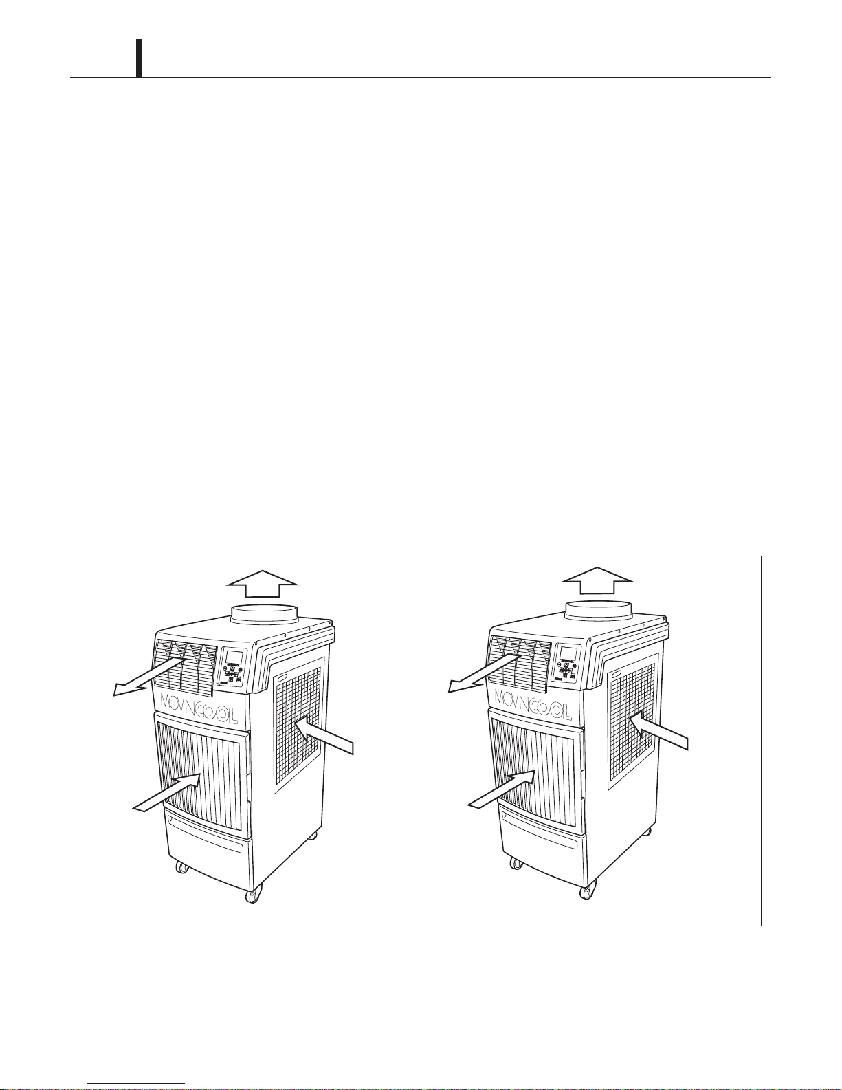
2.4 Basic Construction
• The Climate Pro 18 is compact in construction because the indoor and the outdoor heat
exchangers are enclosed in one unit. The interior is divided into three sections. The upper front
face is equipped with the indoor heat exchanger, and the lower front face contains the drain tank
and condensate pump (optional accessory). The rear section contains the outdoor heat
exchanger, the compressor and the control box.
2.5 Air Flow
• In Cool Mode, air drawn from the outdoor air inlet passes through the heat rejection coil
(condenser) and discharges hot air through the exhaust hot air outlet. Air take in from the indoor
air inlet passes through the heat absorption coil (evaporator) and discharges the cool air through
the cool air outlet.
• In Heat Mode, the refrigeration in the unit operates in reverse cycle and the heat rejection coil
(condenser) becomes the heat absorption coil (evaporator). Air drawn from the outdoor air inlet
passes through this heat absorption coil and discharges cool air through the exhaust cool air
outlet. Air taken in from the indoor air inlet passes through the heat rejection coil and discharges
hot air through the hot air outlet.
Page 11

Operation Section
2.6 Compressor and Fans
• The compressor is hermetically sealed. The indoor fan is a centrifugal type and operated by a
3-speed motor to draw air through the indoor air inlet. The outdoor fan is also a centrifugal type
and operated by a 1-speed motor to draw air through the outdoor air inlet.
2.7 Drain Tank
• A 5.0 gal (19 L) drain tank is supplied with the Climate Pro 18. The condensate (water) is
collected into the tank.
The drain switch activates and stops the operation when tank reaches the level of approximately
4.0 gal (15 L).
11
Page 12

12
< NOTE >
Operation Section
3. SPECIFICATIONS
3.1 Technical Specifications
Technical Specifications - Table 1
ITEM SPECIFICATIONS
Electronic Features Operation Digital Programmable
Electrical Characteristics Voltage Requirement 1 Phase, 115 V, 60 Hz
Operating Voltage Range Max. 127 V
Min. 104 V
Starting Current 65 A
Recommended Fuse Size 20 A
FLA 15.6 A
LRA 65 A
Cooling Performance
Rating Condition
(AHAM PAC-1-2009)
Indoor Heat Exchanger:
80 °F
(26.7 °C), 50 %RH
Outdoor Heat Exchanger:
80 °F (26.7 °C), 50 %RH
Heating Performance
Rating Condition
(AHAM RAC-1-2008)
Indoor Heat Exchanger:
70 °F (21.1 °C), 57 %RH
Outdoor Heat Exchanger:
47 °F (8.3 °C), 75 %RH
Compressor Type Hermetic Rotary
Ventilation Equipment for
Outdoor Coil
Total Cooling Capacity*
Sensible Cooling Capacity*
Power Consumption*
Current Consumption*
SD-EER 9.5
Power Factor
Total Heating Capacity 13,700 Btu/h (4,010 W)
Power Consumption 1.61 kW
Current Consumption 14.7 A
COP 2.49
Power Factor
Output 1.16 kW
Type of Outdoor Coil (Heat Exchanger) Plate Fin
Type of Fan Centrifugal Fan
1
1
1
1
14,600 Btu/h (4,270 W)
9,900 Btu/h (2,900 W)
1.54 kW
14.1 A
95 %
95 %
Air Flow 700 CFM (1,190 m3/h)
Max. External Static Pressure 0.23 IWG (57 Pa)
Motor Output 0.135 kW
*1 : With outdoor heat exchanger air outlet duct 10 feet (3.0 m) vertical head lift from the ground to the ceiling.
Page 13

Technical Specifications - Table 2
ITEM SPECIFICATIONS
Operation Section
13
Ventilation Equipment for
Indoor Coil
Power Cord NEMA Plug Configuration 5-20
Refrigerant Refrigerant Control Electronic Expansion Valve
Signal Connection Fire Alarm Input 1 (FA-1, FA-2) • No-voltage contact input
Type of Indoor Coil (Heat Exchanger) Plate Fin
Type of Fan Centrifugal Fan
Air Flow High 540 CFM (918 m3/h)
Medium 440 CFM (748 m3/h)
Low 350 CFM (595 m3/h)
Max. External Static Pressure 0.31 IWG (77 Pa)
Motor Output High 0.12 kW
Medium 0.045 kW
Low 0.017 kW
Gage x Length 12 AWG (3-core) x 10 ft (3.0 m)
Type R-410A
Amount 1.94 lb (0.88 kg)
Fire Alarm Input 2 (Al-1, Al-2)
Warning Signal Output (OS-1, OS-2) 2 A at 30 V (DC/AC) max. with resis-
• Contact resistance less than 100
ohm
tive load
External Wall Thermostat Millivolt Type With terminals RC, O/B, G, Y
24VAC Type With terminals C, O/B, G, Y,
24VAC RC/RH
Dimension W x D x H 21 x 27 x 50 in
(533 x 686 x 1,270 mm)
Weight Net 214 lb (97 kg)
Shipping 250 lb (113 kg)
Drain Tank Capacity 5.0 gal (19 L)
Cooling Operating Condition
Range
Heating Operating Condition
Range
Inlet Air Temperature Max. 95 °F (35 °C), 60 %RH
Min. 65 °F (18 °C), 50 %RH
Without Outdoor Heat
Exchanger Duct
With Outdoor Heat
Exchanger Duct
Max. 80 °F (26.7 °C), 50 %RH
Min. 40 °F (4.4 °C), 50 %RH
Max. 80 °F (26.7 °C), 50 %RH
Min. Indoor Heat Exchanger:
40 °F (4.4 °C), 50 %RH
Outdoor Heat Exchanger:
24 °F (-4.4 °C), 50 %RH
Page 14

14
< NOTE >
Operation Section
Technical Specifications - Table 3
ITEM SPECIFICATIONS
Maximum Equivalent Duct
Length
Sound Level*
Safety Devices Compressor Overload Protector Included
2
Indoor Heat Exchanger Duct 25 ft (7.6 m)
Outdoor Heat Exchanger Duct 100 ft (30.5 m)
With Outdoor Heat
Exchanger Duct
Without Outdoor Heat
Exchanger Duct
Fan Motor Overload Protector (Indoor/Outdoor) Included
Freeze Protection Thermistor Included
Drain Switch Included
Automatic Restart (Power Interruption) Included
Compressor Time Delay Included
High Pressure Interruption Included
Signal Input/Output Included
Current Fuse for Relay Board Included
High 61 dB (A)
Medium 60 dB (A)
Low 59 dB (A)
High 62 dB (A)
Medium 61 dB (A)
Low 60 dB (A)
Current Fuse for Drain Pan Heater and 4-Way
Val ve
Cutoff Fuse for Drain Pan Heater Included
Control Devices Defrost Heating Included
Drain Pan Heater Heating Included
Delay Timer for Indoor
Fan
Temperature Control Included
Programmable Timer Included
3-Speed Fan Included
Loss of Cooling or Heating Included
On-Screen Self-Diagnostic Codes Included
Cooling Not included
Heating Included
Included
• Specifications are subject to change without notice.
*2 : Measured at 3 feet (1.0 m) from surface of the unit.
Page 15

3.2 Characteristics in Cool Mode
ILL00853-00
Cooling Capacity (kBtu/h)Relative Humidity (%)
Wet Bulb Temp. ºF (ºC)
11
17
16
15
14
40
50
60
70
80
90
100
13
12
50
(10)55 (13) 60(16)
65
(18)
70
(21)
75
(24)
80
(27)
85
(29)
90
(32)
95
(35)
Dry Bulb Temp. ºF (ºC)
50
(10)55 (13) 60(16)
65
(18)
70
(21)
75
(24)
80
(27)
85
(29)
90
(32)
95
(35)
Hi
Mid
Lo
• All characteristic values are within ±10% tolerance.
(1) Cooling capacity curve
Operation Section
15
Page 16

16
ILL00854-00
Cooling Capacity (kBtu/h)
11
17
16
15
14
13
12
50
(10)55 (13) 60(16)
65
(18)
70
(21)
75
(24)
80
(27)
85
(29)
90
(32)
95
(35)
Example: Dry bulb: 80 ºF (27 ºC), 50 %RH, High fan speed
Cooling capacity:14.6 kBtu/h
Relative Humidity (%)
Wet Bulb Temp. ºF (ºC)
40
50
60
70
80
90
100
Dry Bulb Temp. ºF (ºC)
50
(10)55 (13) 60(16)
65
(18)
70
(21)
75
(24)
80
(27)
85
(29)
90
(32)
95
(35)
Hi
Mid
Lo
Operation Section
How to read the cooling capacity curve
Page 17

(2) Power consumption curve
Power Consumption (W)Relative Humidity (%)
Wet Bulb Temp. ºF (ºC)
1.1
40
60
80
100
50
(10)55 (13) 60(16)
65
(18)
70
(21)
75
(24)
80
(27)
85
(29)
90
(32)
95
(35)
Dry Bulb Temp. ºF (ºC)
50
(10)55 (13) 60(16)
65
(18)
70
(21)
75
(24)
80
(27)
85
(29)
90
(32)
95
(35)
1.9
1.8
1.7
1.6
1.5
1.4
1.3
1.2
Hi
Mid
Lo
ILL00855-00
Power Consumption (W)Relative Humidity (%)
Wet Bulb Temp. ºF (ºC)
1.1
40
50
60
80
100
50
(10)55 (13) 60(16)
65
(18)
70
(21)
75
(24)
80
(27)
85
(29)
90
(32)
95
(35)
Dry Bulb Temp. ºF (ºC)
50
(10)55 (13) 60(16)
65
(18)
70
(21)
75
(24)
80
(27)
85
(29)
90
(32)
95
(35)
1.9
1.8
1.7
1.6
1.5
1.4
1.3
1.2
Example: Dry bulb: 80 ºF (27 ºC), 50 %RH, High fan speed
Power consumption : 1.54 kW
Hi
Mid
Lo
ILL00856-00
Operation Section
17
How to read the power consumption curve
Page 18

18
ILL00857-00
Current Consumption (A)Relative Humidity (%)
Wet Bulb Temp. ºF (ºC)
10
40
60
80
100
50
(10)55 (13) 60(16)
65
(18)
70
(21)
75
(24)
80
(27)
85
(29)
90
(32)
95
(35)
Dry Bulb Temp. ºF (ºC)
50
(10)55 (13) 60(16)
65
(18)
70
(21)
75
(24)
80
(27)
85
(29)
90
(32)
95
(35)
18
17
16
15
14
13
12
11
Hi
Mid
Lo
Current Consumption (A)Relative Humidity (%)
Wet Bulb Temp. ºF (ºC)
10
40
50
60
80
100
50
(10)55 (13) 60(16)
65
(18)
70
(21)
75
(24)
80
(27)
85
(29)
90
(32)
95
(35)
Dry Bulb Temp. ºF (ºC)
50
(10)55 (13) 60(16)
65
(18)
70
(21)
75
(24)
80
(27)
85
(29)
90
(32)
95
(35)
Example: Dry bulb: 80 ºF (27 ºC), 50 %RH, High fan speed
Current consumption : 14.2 A
18
17
16
15
14
13
12
11
Hi
Mid
Lo
ILL00858-00
Operation Section
(3) Current consumption curve
How to read the current consumption curve
Page 19

(4) Cool air temperature difference curve
ILL00859-00
Relative Humidity (%)
15 (8.3)
20 (11.1)
25 (13.9)
30 (16.7)
30 40 50 60 70 80
10 (5.6)
Delta-T ºF(ºC)
Hi
Mid
Lo
Operation Section
19
Page 20

20
ILL00881-00
35
(2)
40
(4)
45
(7)50(10) 55 (13) 60 (16) 65(18)70(21) 75(24) 80(27)85(29)
Heating capacity (kBtu/h)
Dry Bulb Temp. ºF (ºC)
10
12
14
16
18
20
Hi
Lo
Mid
Operation Section
3.3 Characteristics in Heat Mode
• All characteristic values are within ±10% tolerance.
(1) Heating capacity curve
Page 21

How to read the heating capacity curve
ILL00882-00
35
(2)
40
(4)
45
(7)50(10) 55 (13) 60 (16) 65(18)70(21) 75(24) 80(27)85(29)
Heating capacity (kBtu/h)
Dry Bulb Temp. ºF (ºC)
Example: Dry bulb: 60 ºF (15.6 ºC), 50 %RH, High fan speed
Heating capacity:16 kBtu/h
10
12
14
16
18
20
Hi
Lo
Mid
Operation Section
21
Page 22

22
ILL00883-00
35
(2)40(4)45(7)50(10) 55 (13) 60 (16) 65(18)70(21) 75(24) 80(27)85(29)
Power Consumption (kW)
Dry Bulb Temp. ºF (ºC)
1.1
1.2
1.4
1.3
1.5
1.6
1.9
1.8
1.7
Hi
Lo
Mid
Example: Dry bulb: 60 ºF (15.6 ºC), 50 %RH, High fan speed
Power consumption: 1.54 kW
35
(2)40(4)45(7)50(10) 55 (13) 60 (16) 65(18)70(21) 75(24) 80(27)85(29)
Power Consumption (kW)
Dry Bulb Temp. ºF (ºC)
1.1
1.2
1.4
1.3
1.5
1.6
1.9
1.8
1.7
Hi
Lo
Mid
ILL00884-00
Operation Section
(2) Power consumption curve
How to read the power consumption curve
Page 23

(3) Current consumption curve
ILL00885-00
35
(2)40(4)45(7)50(10) 55 (13) 60 (16) 65(18)70(21) 75(24) 80(27)85(29)
Current Consumption (A)
Dry Bulb Temp. ºF (ºC)
11
12
14
13
15
16
18
17
Hi
Lo
Mid
Example: Dry bulb: 60 ºF (15.6 ºC), 50 %RH, High fan speed
Current consumption: 14 A
35
(2)40(4)45(7)50(10) 55 (13) 60 (16) 65(18)70(21) 75(24) 80(27)85(29)
Current Consumption (A)
Dry Bulb Temp. ºF (ºC)
11
12
14
13
15
16
18
17
Hi
Lo
Mid
ILL00886-00
Operation Section
23
How to read the current consumption curve
Page 24

24
ILL00887-00
35
(2)40(4)45(7)50(10) 55 (13) 60 (16) 65(18)70(21) 75(24) 80(27)85(29)
Delta-T ºF (ºC)
Dry Bulb Temp. ºF (ºC)
15(8.3)
20 (11.1)
30 (16.7)
25 (13.9)
35 (19.4)
40 (22.2)
50 (27.8)
45 (25)
Hi
Lo
Mid
Operation Section
(4) Hot air temperature difference curve
Page 25

Operation Section
ILL00860-00
High Pressure Switch
Indoor Heat
Exchanger
Accumulator
Electronic Expansion
Valve
Electronic Expansion
Valve Controller
Outdoor Heat Exchanger
4-Way Valve Controller
Compressor
4-Way Valve
4. REFRIGERATION SYSTEM
4.1 Refrigeration System Construction
The component parts of the refrigeration system include the following:
• Compressor, Accumulator, Indoor and Outdoor heat exchangers, High pressure switch,
Electronic expansion valve with controller, 4-Way valve with controller
These parts are all connected by copper tubing. All the connections have been brazed.
25
Page 26

26
ILL00889-00
MF1
(Indoor
Fan Motor)
Outdoor Heat
Exchanger
MF2
(Outdoor
Fan Motor)
EXV (Electronic Expansion Valve)
Compressor
HPRS
(High Pressure Switch)
CTS1
(Indoor Pipe Thermistor)
ODS
(Outdoor Air Inlet Thermistor)
Indoor Heat
Exchanger
Air InAir In
EMV
Accumulator
OLC (Compressor Overload Relay)
CTS2
(Compressor Pipe
Thermistor)
4-Way Valve
RTS
(Indoor Air
Inlet Thermistor)
CTS3 (Outdoor Pipe Thermistor)
Flow of Refrigerant:
Cool Mode
Heat Mode
Operation Section
Page 27

Operation Section
ILL00861-00
Discharge Gas (High Pressure)
Accumulator
Strainer
Suction Gas (Low Pressure)
Blade
Discharge Valve
Oil
Lubricator
Roller
Cylinder
Rotor
Stator
Terminal
4.2 Compressor
• The compressor used for the unit is hermetically sealed. The compressor and the compressor
motor are in one casing.
(1) Compressor construction
•The construction of a rotary type compressor is divided into two mechanisms; the drive
mechanism (compressor motor), and the compression mechanism (compressor). When the
rotor shaft of the motor (drive mechanism) turns, the roller (compression mechanism) rotates to
compress the refrigerant.
27
Page 28

28
I000510
Discharge
Hole
Cylinder
Blade
Spring
Suction
Hole
Discharge
Val ve
Shaft
Roller
Operation Section
(2) Basic compressor operation
•The roller (compression mechanism) is set
eccentrically with a certain distance given from
the axis of the center of the cylinder. A spring
loaded blade is mounted on the cylinder. The
roller turns to compress the refrigerant in the
space between the cylinder and eccentrically
mounted roller. The blade is in contact with the
roller by means of spring force. The blade
partitions the space between the suction side
and the discharge side to keep compressed refrigerant from returning to the suction side. There
is no suction valve. The discharge valve is designed not to open until the pressure of the
refrigerant within the cylinder reaches or exceeds discharge side pressure. As a result, the
discharge valve prevents the backward flow of refrigerant gas.
Page 29

(3) Operation
I001676
Blade
Discharge
Val ve
Roller
I001677
Blade
Discharge
Val ve
Roller
I001678
Blade
Discharge
Val ve
Roller
I001679
Blade
Discharge
Val ve
Roller
Operation Section
29
1) Start of compression
1) The cylinder is filled with low pressure gas.
2) Since pressure in the discharge chamber is
higher than in the cylinder, the discharge
valve is kept closed.
2) Suction and compression
1) The pressure in the cylinder increases
gradually.
2) Refrigerant suction begins on the suction
side of the cylinder.
3) The discharge valve remains closed.
3) Discharge
1) The pressure in the cylinder exceeds that in
the discharge chamber, and the discharge
valve opens.
2) On the suction side, refrigerant suction
continues.
4) Completion of compression
1) When compression is completed, all of the
refrigerant has been drawn from the suction
chamber.
2) Operation then returns to step 1) (Start of
compression) and the above process of
suction and compression continues
repeatedly in succession.
Page 30

30
I001680
Oil Feed Groove
Oil Hole
Oil Scrapper
Roller
Rotor
Cylinder
Hollow Shaft
Eccentric Shaft
Operation Section
(4) Compressor lubrication
•The lubrication system is comprised of a hollow
shaft, an oil scraper mounted at the end face,
hollow shaft, a shaft journal (shaft bearing),
and the lubrication groove for the shaft journal.
The lubrication groove is wider than the oil
hole. When the shaft turns, oil is scraped
upward by the oil scraper along the inside
diameter of the hollow shaft. The oil is fed
through the oil hole by centrifugal force, then
supplied to the lubrication groove for each
shaft journal, lubricating the bearing. In this
lubrication system, oil enters into each bearing
separately and returns to the oil reservoir. This
system effectively prevents bearing
temperature increases, and offers high
reliability. In addition, the specially treated
shaft journal keeps the bearing from being damaged during high temperature operation.
4.3 Outdoor Heat Exchanger
• The outdoor heat exchanger coil uses copper tubes that are covered with the thin aluminum
protections called plate fins. In cool mode, heat is given off and absorbed by air being pulled
across these fins by the centrifugal fan, and then expelled through the exhaust hot air outlet. In
heat mode, this heat exchanger coil becomes heat absorption coil, and then cool air is expelled
through the exhaust cool air outlet.
4.4 Indoor Heat Exchanger
• The indoor heat exchanger coil is covered with plate fins. In cool mode, heat is removed from
the air being pulled across the indoor heat exchanger by the centrifugal fan and the resulting
cool air is expelled through the cool air outlet grill. In heat mode, this heat exchanger becomes
heat rejection coil, and then hot air is expelled through the hot air outlet grill.
Page 31

Operation Section
I001768
Pressure of Refrigerant
Movable Point
Snap Disk
Pin
Terminal
Lead Wires
Stationary Point
Molding by Resin
Case
ILL00878-00
Suction Gas (Low Pressure)
To Compressor
4.5 High Pressure Switch
• The high pressure switch prevents the outdoor
heat exchanger and compressor from being
damaged by excessive high pressure in the
high pressure line of the refrigeration cycle.
The switch is normally closed. The snap disk
responds to the variations in pressure and, if
pressure is abnormally high, the snap disk
moves down to push the pin down, causing the
internal contacts to open. This interrupts the
ground signal at the control board (CN18 connector) which turns the compressor off.
• Possible causes of this trouble include:
- The air filter for the outdoor heat exchanger is dirty, restricting air flow.
- The blower for the outdoor heat exchanger is defective.
31
4.6 Accumulator
•The accumulator is mounted on the suction gas
piping between the 4-way valve and the
compressor. The accumulator separates the
liquid refrigerant from the gas refrigerant,
allowing only the gas refrigerant to enter the
compressor. In the accumulator, suction gas is
led into a cylindrical vessel where the speed of
the gas is decreased. This process separates
the refrigerant contained in the gas by the force
of gravity, causing the refrigerant to accumulate at the bottom of the vessel. As a result, the
compressor is protected from possible damage caused by liquid refrigerant intake.
Page 32

32
I003162
Refrigerant
Flow
Valve Spring Spring
Valve Holder
Val ve
Control Coil
Magnet
Stopper
Delivery Screw
Val ve
ILL00862-00
Operation Section
4.7 Electronic Expansion Valve
• In cool mode, the electronic expansion valve
causes rapid refrigerant expansion by injecting
"high temperature, high pressure liquid
refrigerant" from the outdoor heat exchanger
through a small orifice. The resultant "low
temperature, low pressure mist refrigerant" is
then sent to the indoor heat exchanger. A
solenoid valve adjusts the refrigerant quantity
according to the indoor heat exchanger air inlet
and outlet temperatures so that the mist
refrigerant can undergo heat exchange in the
indoor heat exchanger under optimal
conditions.
• In heat mode, the electronic expansion valve
operates reversal of cool mode.
4.8 4-Way Valve
• The 4-way valve allows a reversal of the
refrigeration cycle, changing from cool to heat
mode. The 4-way valve is powered on during
heat mode. The cycle reversal is initiated by a
small pilot solenoid valve that moves a slider,
thereby changing the direction of the
refrigerant.
• The 4-way valve coil ensures reliable
changeover from cool to heat mode. The valve
is connected to the discharge and suction pipes. This valve coil comes with two lead wires that
are connected to the relay board circuit. The 4-way valve coil is encapsulated in epoxy resin to
protect the winding from liquids.
4.9 Drain Pan for Outdoor Heat Exchanger
• The drain pan for the outdoor heat exchanger comes with a built-in sheet heater to prevent the
drain pan from freezing up. The sheet heater is the product that wires the cord-type heater with
silicon rubber or vinyl chloride resin insulation on aluminum foil.
Page 33

ILL00871-00
F23
1
1
4
1
4 13
3 4 3 5
4 3 54335
5
1 2
1 3 1 2 2 3
121 41 7
CC
OLC
CF2 CF1
CN
CN CN
DS HPRS
CN
EXV
CN HTR
TF3
G
G
G
GG
G
T1 TRR1
F1
1
2
1
2
S
R
C
H
M
L
1
2
1
2
1
Attachment Plug
Transformer
Compressor Motor
Evaporator Fan Motor (Indoor Fan Motor)
Condenser Fan Motor (Outdoor Fan Motor)
Capacitor for MC
Capacitor for MF1
Capacitor for MF2
Heater
Four-Way Valve
Electronic Expansion Valve
Relay Board
Control Board
Overload Relay for MC
Inner Overload Relay for MF1
Inner Overload Relay for MF2
Drain Switch
AC115V, 1PH, 60Hz, 20A
TB1
MC
EMV
MF2
IOLF2
MF1
IOLF1
TF1 TF2
AC115V
CN01
CN02
CN03
CN30
CB
CN37 CN11 CN12
RB
RTS CTS1CTS2CTS3 ODS
1 6
CN14
1
1
5
6
CN18
TB2
JUMPER
LINE
TB3
CN34
1
4
CN31
RL07RL04RL03 RL08RL06
CN27 CN26CN25
RL01RL09
RL02
CN17
1
3
1
6
CN19
AC20V
TNS
AP
TNS
MC
MF1
MF2
CC
CF1
CF2
H T R
E MV
EXV
R B
C B
OLC
IOLF1
IOLF2
D S
H P R S
R TS
C TS1
C TS2
C TS3
O D S
TB1
TB2
TB3
F1
F2
T F1
T F2
T F3
High Pressure Switch
Room Thermistor (Indoor Air Inlet Thermistor)
Evaporator Pipe Thermistor
(Indoor P
ipe Thermistor)
Compressor Pipe Thermistor
Condenser Pipe Thermistor
(Outdoor Pipe Thermistor)
Outdoor Thermistor
(Outdoor Air Inlet Thermistor)
Terminal Block
Terminal Block
Terminal Block
Fuse
Fuse
Fuse for TNS
Fuse for TNS
Fuse for HTR
GND
RX
TX
+5V
AL-2
AL-1
FA-2
FA-1
OS-2
OS-1
Millivolt RC
(Jumper)
24VAC C
O/B
G
Y
24VAC RC/RH
24VAC Hot
24VAC Neutrol
5. ELECTRICAL SYSTEM
5.1 Wiring Diagram
Operation Section
33
Page 34

34
Operation Section
5.2 Basic Operation of Electrical Circuit
• There are two basic components used to control the operation of electrical system:
- Control panel assembly
- Service box
• The control panel assembly contains the display panel and keypad. The service box contains all
input and output devices such as temperature devices, sensors, relays, switches and
microprocessor.
(1) Fan Only mode
• Fan Only mode can be selected by pressing the MODE button on the control panel and
confirming to start the operation of Fan Only mode. In this mode, the fan relay RL02 is closed
and the fan speed relays are either closed or opened depending on fan speed setting. When fan
Hi speed is set, the relay RL03 terminal 4 and the relay RL04 terminal 4 are closed. When fan
Mid speed is set, the relay RL03 terminal 3 and the relay RL04 terminal 4 are closed. When fan
Lo speed is set, the relay RL04 terminal 3 is closed.
(2) Cool mode
• Cool mode can be selected by pressing the MODE button on the control panel and confirming
to start the operation of Cool mode. In this mode, the indoor fan relays RL02, RL03, and RL04
are operated based on fan speed setting, and the outdoor fan relay RL09 and the compressor
relay RL01 are operated after the 120 seconds time delay has been expired.
(3) Heat mode
• Heat mode can be selected by pressing the MODE button on the control panel and confirming
to start the operation of Heat mode. In this mode, the 4-way valve relay RL06 and the indoor fan
relays RL02, RL03, and RL04 are operated based on fan speed setting. The outdoor fan relay
RL09 and the compressor relay RL01 are operated after the 120 seconds time delay has been
expired. During Heat mode, the heater relay RL08 is closed when the ODS (outdoor air inlet
thermistor) detects below 24 °F (-4 °C) to prevent the drain pan from freezing and opened when
the ODS detects above 43 °F (6 °C).
Page 35

Operation Section
ILL00863-00
Terminal Block 1 (For Power)
Relay Board
Relay Board Fuse (F2)
(1 A, 250 V)
Terminal Block 2
(For Input/Output Signal)
Terminal Block 3
(For External Thermostat)
Fuse (F1)
(1.5 A, 250 V for
4-Way Valve,
Drain Pan Heater of
Outdoor Heat Exchanger)
Compressor Motor
Capacitor
Transformer (For Relay Board)
Fan Motor Capacitor
<Service Box>
5.3 Service Box
(1) Capacitors
• The capacitors are used to temporarily boost the power output available to the fan motors and
the compressor at start-up.
• The specifications of each capacitor are listed below:
Capacitor Application Volta ge Rating Capacitance
Fan Motors 370 VAC 7.5 μF
Compressor Motor 370 VAC 60 μF
35
(2) Terminal blocks
• There are three terminal blocks in the service box, a power terminal block used for the power
line connection, and two low signal terminal blocks used for external thermostat and signal
connections.
Page 36

36
< NOTE >
ILL00865-00
Fuse
DIP Switch
LEDs
(3) Relay board
• The relay board is powered by 20 VAC from the secondary side of the step down transformer.
This voltage is then converted from 20 VAC to 12 VDC and supplied to the relay driver circuits
on the board. The 12 VDC is then converted again into 5 VDC and supplied to the
microprocessor, sensors, and switches on the relay board.
• The relay board contains surge protection circuit, AC power interruption and monitoring circuit,
fuse, and DIP switches (no function and are defaulted to the OFF positions). There are also 5
LEDs on the relay board that provides a visual tool to quickly diagnose problems on the relay
board. These LED's functional descriptions and status are listed in the table below.
LED Number Function and Description Normal Status
Operation Section
LED01 Indicates that the +5 VDC line is normal. Green LED is on.
LED02 Not in use. Not in use.
LED03 Indicates that the +12 VDC line is normal. Green LED is on.
LED04 Indicates that serial connection between the relay
board and the controller board is normal.
LED05 Indicates that serial connection between the relay
board and the controller board is normal.
Yellow LED is blinking.
Yellow LED is blinking.
The relay board must be serviced as a complete assembly. It has only one serviceable
component, the fuse. (see below)
• The relay board fuse provides protection
against damage to the step-down transformer.
It must be replaced with the exact type of fuse
or an equivalent.
Specifications:
- 1 A, 250 V
CAUTION
Failure to use the exact type of fuse could result in damage to the unit and/or to components. It
could also void the warranty of the unit.
Page 37

(4) Transformer for relay board
ILL00879-00
Secondary
20 V
<Wiring Diagram>
40 VA, 60 Hz
1
5
10
6
4
2
Primary
115 V
ILL00905-00
Secondary
Primary
Connected to
Signal Terminals
(24VAC Neutral,
24VAC Hot)
40 VA, 60 Hz
Connected to
Terminals
(R1, T1)
3
10
6
120 V24 V
3
5
10
6
<Wiring Diagram>
• A dry-type transformer rated 40 VA is equipped
within the unit to provide step down voltage
from 115 V to 20 V.
• Terminals 1 and 5 are connected to 115 V
power source to supply power to secondary
side.
• Terminals 6 and 10 of the secondary side are
connected to the relay board to provide 20 V
output.
Specifications:
- Type: Dry type
- Rated VA: 40 VA
- Power Requirement: 1 Phase, 60 Hz
Operation Section
37
- Primary Voltage: 115 V
- Secondary Voltage: 20 V
(5) Optional transformer for 24VAC thermostat (field supplied)
• A dry-type transformer rated 40 VA is equipped
within the unit to provide step down voltage
from 115 V to 24 V.
• Terminals 3 and 5 are connected to 115 V
power source to supply power to secondary
side.
• Terminals 6 and 10 of the secondary side are
connected to the signal terminals to provide 24
V output.
Specifications:
- Type: Class 2 transformer
- Rated VA: 40 VA
- Power Requirement: 1 Phase, 60 Hz
- Primary Voltage: 115 V
- Secondary Voltage: 24 V
Page 38

38
< NOTE >
ILL00866-00
CF1-1 (White)
CF1-2 (White/Brown)
RL03-NC (H) (Black)
RL03-NO (M) (Red)
RL04-NO (L) (Blue)
Ground
(Green/Yellow)
ILL00867-00
CF2-1 (White)
CF2-2 (White/Brown)
Ground
(Green/Yellow)
RL09-NO (Black)
Operation Section
5.4 Fan Motor
(1) Indoor fan motor
• The indoor fan motor is a 1 phase, induction
type 3 speed motor.
Specifications:
- Rated Voltage: 115 V, 60 Hz
- Rated Output: Hi - 115 W, Mid - 44.4 W, Lo -
15.4 W
(2) Outdoor fan motor
• The outdoor fan motor is a 1 phase, induction
type 1 speed motor.
Specifications:
- Rated Voltage: 115 V, 60 Hz
- Rated Output: 127 W
An internal overload relay is used to protect the fan motor. This relay is built into the fan motor and
interrupts the flow of current when there is an over current situation, or if abnormally high
temperature builds up in the fan motor.
Page 39
Operation Section
I001691
Bimetal
Terminal
Points
ILL00872-00
Reset Button
Test Button
5.5 Compressor
(1) Compressor motor
• The compressor motor is a 1 phase, induction type motor and is contained within the same
housing as the compressor.
Specifications:
- Rated Voltage: 115 V, 60 Hz
- Rated Output : 1160 W
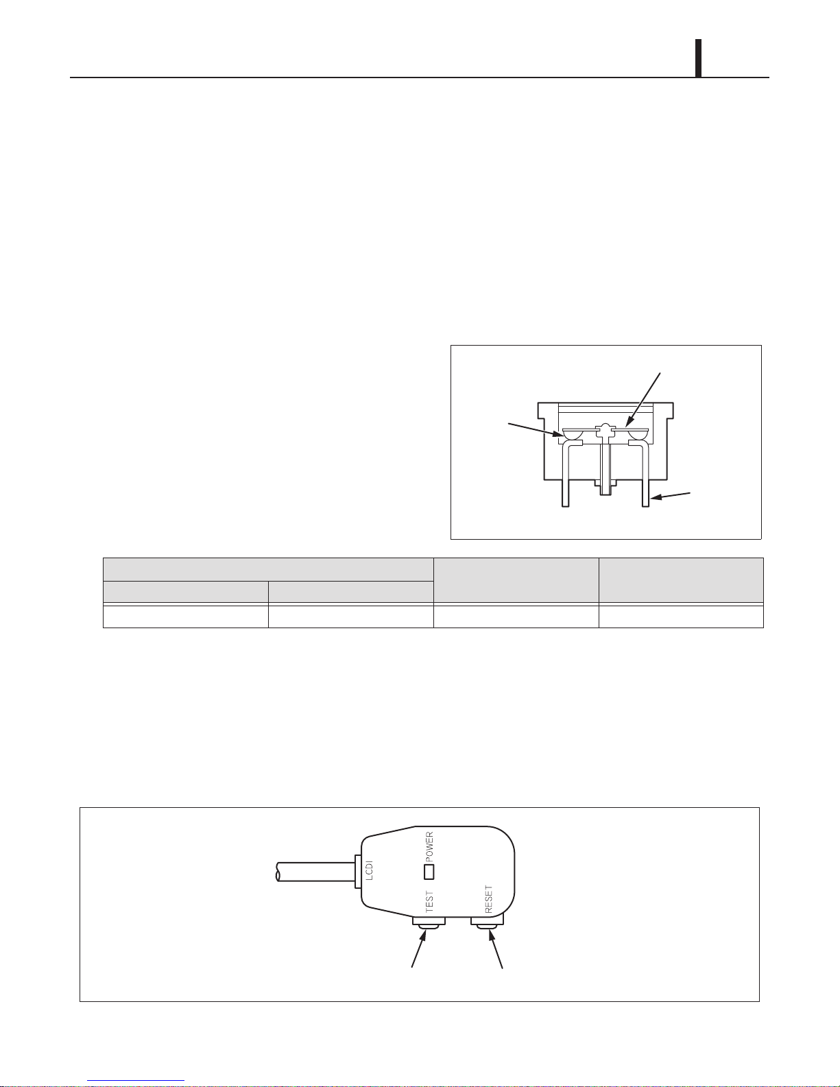
(2) Compressor overload relay
• An external compressor overload relay is used
to protect the compressor motor. This relay is
mounted within the connector housing that
attaches to the top of the compressor. The
39
relay interrupts the flow of current when there is
an overload condition and, high temperature
builds up in the compressor.
Operating Temperature
OFF (Open Contacts) ON (Closed Contacts)
302 °F (150 °C)
156 °F (69 °C) 19.0 MRA4720-12027
Non-Operating Limit at 176 °F
(100 °C) (A)
Marking
5.6 Power Cord with LCDI
• The Climate Pro 18 is equipped with UL recognized LCDI power cord and NEMA plug
configuration (5-20). The appropriate outlet must be used for this plug type. LCDI is used for
monitoring leakage current. Once leakage current is detected, LCDI de-energizes the unit.
Page 40

40
ILL00873-00
2
NC
C
1
DS2
DS1
Indoor Heat Exchanger
Drain Pan
Drain Tube
Drain Tank
Fulcrum
Drain Water
Base Plate Top
Base Plate
Base Plate Bottom
Drain Switch
Spring
To CN18
Operation Section
5.7 Drain Switch
• The Climate Pro 18 is equipped with a drain switch. When the drain tank accumulates
approximately 4.0 gal (15 L) of condensate (water) in the drain tank, the drain switch sends a
signal to the microprocessor. The microprocessor stops all operation of the unit, displays the
"FL" on the LCD and closes the contact of output signal.
• This system utilizes a 0.1 A, 125/250 VAC micro-switch for this function. When drain water
accumulates approximately 4.0 gal (15 L) in the drain tank, the drain tank base plate, which is
supported at its fulcrum, is pushed down in the arrow direction as shown in the figure below.
• When the drain tank base plate is forced down, the top of the drain tank base plate turns off the
contacts #1-#2 of the micro switch. This causes the ground signal at the CN18 connector of the
relay board to go open. When the microprocessor detects this event, it shuts the unit off, displays
the "FL" on the LCD and closes the contact of output signal.
• When the drain tank is removed (or the drain tank is emptied), the top of the drain tank base
plate returns to its original position from the tension of the coil spring. Then contacts #1-#2 of
the drain switch close. This provides a ground to the microprocessor through the CN18
connector.
Page 41

Operation Section
41
(1) How to re-start the unit
•
Press the START/STOP button on the control panel. The unit returns to the previous operation mode
.
5.8 Condensate Pump Kit (Optional)
• The Climate Pro 18 model comes standard with a drain tank, which collects the water that forms
on the heat exchangers during normal operation. If the unit is required to operate continuously
without periodically emptying this tank, a condensate pump may be needed. A condensate
pump kit is available for this model.
5.9 Automatic Restart after Power Interruption (Automatic Recovery Feature)
• The program within the microprocessor of the Climate Pro 18 contains a feature that
automatically restarts the unit after power is lost and regained. The unit returns to the same
operation mode as it was prior to the loss of power. Any preset program is retained in the
memory in the event power loss occurs.
5.10 Compressor Protection
• There is a time delay program within the microprocessor. This prevents a heavy load from being
applied on the compressor motor when restarting the unit cool or heat mode after a very short
period of time. This delay is in effect any time when the compressor is turned on by selection of
the cool or heat mode operation. temperature set point (thermostatic control), power interruption
restart or condensate pump (optional) operation.
Specifications:
Time delay
- 120 ± 20 sec.
5.11 Temperature Control
• The compressor operation during cool or heat mode operation is controlled by the
microprocessor which receives input signals from the RTS (indoor air inlet thermistor) and the
setting of the temperature set point. The temperature set point (desired room temperature) can
be adjusted by pressing the TEMP+ or -TEMP button on the control panel. The adjustment
range of the temperature set point is:
For cool mode:
- 65 °F ~ 90 °F (18 °C ~ 32 °C)
For heat mode:
- 55 °F ~ 80 °F (13 °C ~ 27 °C)
Page 42

42
Operation Section
6. EXTERNAL DEVICE CONNECTION
6.1 Millivolt Thermostat Connection (Optional Accessory)
WARNING
Disconnect power before installation. Beware that some residual voltage may remain in
the unit immediately after the power is disconnected.
1) Select the proper location where the millivolt thermostat can be conveniently accessed and
install it at the selected location.
CAUTION
Do not install the millivolt thermostat where artificial heating condition may occur (i.e. hot stove,
hot pipe, and fireplace or under direct sunlight).
2) Set the millivolt thermostat to cool or heat mode without power connection on the unit. Prepare
the millivolt thermostat wires.
Recommended wire size:
- 18 ~ 20 AWG
3) Turn the unit off and unplug the power cord.
Take out seven (7) screws and remove the
service panel from rear of the unit.
Cap
Screws (7)
ILL00806-00
4) Squeeze the inner latches and push out the
black cap from inside the panel. Insert the
millivolt thermostat wires through the hole in
the rear panel.
Cap
Latch
ILL00046-01
Page 43

Operation Section
< NOTE >
Neutral
Hot
43
5) Connect the millivolt thermostat wires to the terminal block according to the connection table
shown below. Reinstall the service panel to the unit.
Service Box
Connection Table
Neutral
Hot
Millivolt
Thermostat
Wire No.
RC
O/B
Y
Unit
Terminal Block 3
Terminal No.
Millivolts RC
O/B
GG
Y
TB3
6) Plug in the power cord.
7) Press MENU/ESC button to go to MENU.
Use TEMP+ or -TEMP button to select
EXTERNAL THERMOSTAT and press ENTER
button to confirm. LCD displays a notification
screen.
Millivolt Thermostat
ILL00776-01
ILL00813-00
If no button is pressed for 1 minute, LCD displays the previous mode.
Page 44

44
Operation Section
8) Use TEMP+ or -TEMP button to select YES
and press ENTER button to confirm. LCD
displays
"EXTERNAL THERMOSTAT
ACTIVATED" and "KEY LOCKED" with the
room temperature. LED color changes from
orange to green.
9) To deactivate thermostat connection, press
and hold MENU button for 5 seconds. Other
buttons are unlocked and the unit enters
standby mode. LED color changes from green
to orange.
ILL00814-00
ILL00815-00
Page 45

Operation Section
24VAC Thermostat Connection Table
24VAC Transformer Connection Table
24VAC RC/RH
24VAC C
24VAC
Thermostat
Wire No.
Unit
Terminal Block 3
Terminal No.
O/B
G
Y
C
O/B
RC/RH
G
Y
R1
24VAC
Trasformer Wire
No.(Primary Side)
Unit
Terminal Block 1
Terminal No.
T1
R1
T1
24VAC Hot
24VAC
Trasformer Wire
No.(Secondary Side)
Unit
Terminal Block 3
Terminal No.
24VAC Neutral
Hot
Neutral
Jumper Plug
24VAC Thermostat
24VAC Transformer
Primary
Secondary
TB3
TB1
Service Box
NeutralNeutral
HotHot
ILL00880-00
6.2 24VAC Thermostat Connection (Field Supplied)
• An optional 24VAC transformer is required with a field supplied 24VAC thermostat.
WARNING
Disconnect power before installation. Beware that some residual voltage may remain in
the unit immediately after the power is disconnected.
45
1) Turn the unit off and unplug the power cord. Refer to the previous section to remove the service
panel and insert the thermostat wires through the hole in the rear panel. Connect the 24VAC
thermostat wires to the terminal block according to the 24VAC thermostat connection table
shown above.
2) Install the 24VAC secondary class 2 transformer to the service box. Insert the secondary side
wires through the upper grommet hole in the service box. Connect the wires to the terminal
blocks according to the 24VAC transformer connection table shown above. All wiring must
comply with applicable local codes, ordinances, and regulations.
Specifications:
- Transformer: Primary 115 V, Secondary 24 V
- Recommended wire size: 18 AWG or 20 AWG
Page 46

46
< NOTE >
< NOTE >
Operation Section
3) Remove the jumper plug from the terminal block. Reinstall the service panel to the unit.
Keep this jumper plug in a safe place to reuse when the 24VAC thermostat is removed from the
unit.
4) Plug in the power cord.
5) Press MENU/ESC button to go to MENU.
Use TEMP+ or -TEMP button to select
EXTERNAL THERMOSTAT and press ENTER
button to confirm. LCD displays a notification
screen.
ILL00813-00
If no button is pressed for 1 minute, LCD displays the previous mode.
6) Use TEMP+ or -TEMP button to select YES
and press ENTER button to confirm. LCD
displays "EXTERNAL THERMOSTAT
ACTIVATED" and "KEY LOCKED" with the
room temperature. LED color changes from
orange to green.
7) To deactivate thermostat connection, press
and hold MENU button for 5 seconds. Other
buttons are unlocked and the unit enters
standby mode. LED color changes from green
to orange.
ILL00814-00
ILL00815-00
Page 47

Operation Section
6.3 Warning Device Connection (Field Supplied)
• The controller of this unit is equipped with a warning signal output relay which can be used to
monitor failure condition of the unit and is compatible with various external warning devices such
as alarm speaker, light indicators, etc.
Specifications:
- Relay type: Form C, normal open dry contact
- Relay output contactor rating: 2 A at 30 V (DC/AC) maximum with resistive load
WARNING
Disconnect power before installation. Beware that some residual voltage may remain in
the unit immediately after the power is disconnected.
1) Turn the unit off and unplug the power cord.
Take out seven (7) screws and remove the
Cap
47
service panel from rear of the unit.
2) Squeeze the inner latches and push out the
black cap from inside the panel.
Insert the warning signal wires through the hole
in the rear panel.
Recommended wire size:
- 16 AWG ~ 22 AWG
Screws (7)
ILL00806-00
Cap
Latch
ILL00046-01
Page 48

48
Service Box
Warning Device
ILL00774-01
NeutralNeutral
HotHot
TB2
Operation Section
3) Connect the warning signal wires to the terminals OS-1 and OS-2 as shown in the above figure.
Reinstall the service panel to the unit.
4) Plug in the power cord.
Page 49

Operation Section
ILL00775-01
Service Box
Alarm Device 1
Alarm Device 2
NeutralNeutral
HotHot
TB2
6.4 Alarm Device Connection (Field Supplied)
• The controller of this unit is equipped with two sets of input signal terminals on the terminal block
which can connect the external alarm devices such as a fire alarm device. The input signal
terminals should only be connected to a close or an open dry contact. When receiving the
signals from the external alarm devices, the unit turns off and does not turn back on until it has
been RESET.
WARNING
Disconnect power before installation. Beware that some residual voltage may remain in
the unit immediately after the power is disconnected.
49
1) Turn the unit off and unplug the power cord.
Refer to the previous section to remove the service
panel and insert the alarm device wires through the hole in the rear panel.
Recommended wire size:
- 16 AWG ~ 22 AWG
2) Connect the alarm signal wires to terminal AI-1 and AI-2 and/or FA-1 and FA-2 as shown in the
above figure. Reinstall the service panel to the unit.
3) Plug in the power cord.
Page 50

50
lLL00778-00
1
7
2
4
8
5
3
6
Operation Section
7. CONTROL PANEL
7.1 Control Panel and LCD Indicators
• Refer to the OPERATION MANUAL supplied with the unit for daily operation.
(1) Control panel
1 START/STOP button Start or stop the unit operation.
2 LED
3 MODE button
4 MENU/ESC button
Illuminate in Orange color for Self-Diagnostic and Standby mode, in Green color
for normal operation.
Select operation mode (FAN ONLY, COOL, and HEAT).
FAN ONLY : Fan operates continuously.
COOL : Once the room temperature reaches the set point temperature, the
unit operates in FAN ONLY mode. When switched from HEAT to
COOL mode operation, the unit initially operates in FAN ONLY
mode.
HEAT : Once the room temperature reaches the set point temperature, the
unit stops. When switched from COOL to HEAT mode operation,
the unit stops until the compressor operates. When FAN mode is
set to AUTO, the fan operates within 1 minute after the compressor
operates.
Display the menu selection screen or to escape from the menu selection
screen.
Page 51

< NOTE >
5 ENTER button Select item in Menu mode.
6 FAN+, -FAN buttons Change fan speeds Hi, MID, LO.
7 TEMP+, -TEMP buttons Change set point temperature.
Operation Section
51
8 LCD
Display operation mode, status, notification, confirmation, and self-diagnostic
codes with two backlight colors.
• When the unit is connected to power, the LED illuminates in orange color, and the LCD displays
date, time and the previous mode setting condition with blue backlight that stays on for 60
seconds, then turns off (standby mode). The backlight turns on again if any button is pressed.
• The RTS (indoor air inlet thermistor) monitors the inlet air temperature versus setpoint
temperature and automatically switches ON and OFF during cooling or heating operation.
• The fan mode control determines whether the fan continues to operate or stop when the
compressor stops during COOL or HEAT mode. The unit has been preset at the factory for
continuous fan operation in COOL and for fan AUTO operation in HEAT mode. Fan mode can be
changed on the control panel under Menu.
Page 52

52
< NOTE >
Operation Section
(2) LCD indicators
2
1
6
10
3
9
7
8
1 Day of the week Indicate day of the week.
2 Time of the day Indicate time of the day.
3 Room Temp
4 Key Locked
Indicate room temperature.
Temperature range: 0 °F ~ 99 °F (0 °C ~ 99 °C)
Indicate keypad is locked.
Disable all buttons on the control panel except MENU/ESC button.
4
5
lLL00779-00
11
lLL00780-00
12
ILL00781-00
Indicate set point temperature. "MIN" or "MAX" indicates minimum or maximum value.
5 Set Temp
6 Fan Only/Cool/Heat Indicate operating mode.
7 Fan Mode Indicate AUTO or ON.
8 Fan Speed Indicate HI, MID or LO.
9 External Indicate external millivolt or 24VAC thermostat is connected.
10 Program Running Indicate Program is running.
11 Defrost
12 Outside Operating Range
Temperature range for COOL mode operation: 65 °F ~ 90 °F (18 °C ~ 32 °C)
Temperature range for HEAT mode operation: 55 °F ~ 80 °F (13 °C ~ 27 °C)
Indicate defrost operation during heating.
When the ambient temperature is low, the unit automatically stops and starts
defrosting operation for maximum 15 minutes ("DEFROST" is displayed).
The unit returns to heating operation after defrosting operation is completed.
Indicate the unit is used outside of the operating condition range.
When the ambient temperature falls outside the operating condition range,
the unit automatically stops and displays this notification.
The unit has been preset at the factory to display the temperature in °F. The temperature scale
can be changed from °F to °C on the control panel under Menu.
Page 53

Operation Section
< NOTE >
< NOTE >
7.2 Operational Status Display
• The operational status of each functional part can be displayed on the LCD while the unit is
running.
(1) Display method
• Press and hold MENU/ESC and ENTER
buttons for 5 seconds.
• Use FAN+ or -FAN button to select "STATUS",
and press ENTER button to confirm. The
operational status content is displayed.
ILL00874-00
53
ILL00875-00
• If no button is pressed for 1 minute, the LCD automatically displays the previous mode.
• Press Menu/ESC button again to return to the previous screen.
Display Code Display Item Display Unit
EXV Electronic expansion valve opening rps
RTS Indoor air inlet thermistor temperature °F/°C
ODS Outdoor air inlet thermistor temperature °F/°C
CTS1 Indoor pipe thermistor temperature °F/°C
CTS2 Compressor pipe thermistor temperature °F/°C
CTS3 Outdoor pipe thermistor temperature °F/°C
RTS2 Not in use. -
Display unit °F or °C can be changed on the control panel. Press MENU/ESC button, select TEMP.
SCALE by TEMP+ or -TEMP button, and press ENTER button. Select °F or °C, and press ENTER
button to confirm.
(2) Exiting operational status display
• To exit the operational status display, press MENU/ESC button.
Page 54

54
< NOTE >
Operation Section
7.3 Record Display
• The record of unit power on time, compressor operating time, defrosting time and self-diagnostic
codes can be displayed on the LCD while the unit is running.
• The unit power on time, compressor operating time, and defrosting time can be stored up to
65500 hours (automatically cleared to 0 hour and start counting).
• The self-diagnostic codes can be stored up to 3 different codes.
(1) Display method
• Press and hold MENU/ESC and ENTER
buttons for 5 seconds.
• Use FAN+ or -FAN button to select
"RECORD", and press ENTER button to
confirm. The record content is displayed.
ILL00876-00
ILL00877-00
• If no button is pressed for 1 minute, the LCD automatically displays the previous mode.
• Press Menu/ESC button again to return to the previous screen.
Page 55

Operation Section
< NOTE >
Display Item Description Display Unit
TOTAL TIME Total unit power on time hr
COOL TIME Compressor operating time during cool mode hr
HEAT TIME Compressor operating time during heat mode hr
DEF. TIME Defrosting time during heat mode hr
DIAGNOSTIC CODE 1 Self-diagnostic code 1: Latest code AL1
(Example)
55
DIAGNOSTIC CODE 2 Self-diagnostic code 2: Previous code before the DIAGNOSTIC
CODE 1
DIAGNOSTIC CODE 3 Self-diagnostic code 3: Previous code before the DIAGNOSTIC
CODE 1 and 2.
If there is no recorded self-diagnostic code, "--" is displayed.
(2) Exiting record display
• To exit the record display, press MENU/ESC button.
AS
(Example)
HP
(Example)
Page 56

56
Repair Section
8. TROUBLESHOOTING
8.1 Troubleshooting
• Before troubleshooting the system, the following inspection should be performed.
WARNING
• Disconnect power supply from the unit before performing any service. Beware that some
residual voltage may remain in the unit immediately after the power is disconnected.
(1) Inspection of power source voltage
• Check the voltage of the power source.
- 1 Phase 115 V (60 Hz)
• Check the operation and condition of the fuse or circuit breaker in the power source.
(2) Inspection of power cord
• Check the power cord. If dirty, wipe off with a clean dry cloth. If damage or excess play is found,
replace it.
(3) Inspection of air filters
• Check the air filters. If dirty, clean the air filters as described in the OPERATION MANUAL
supplied with the unit. If damage is found, replace it.
(4) Inspection of drain tank
• Check the drain tank and empty the water. If damage is found, replace it.
The following pages (page 57 to 68) are self-diagnostic codes and troubleshooting information.
Page 57

Repair Section
ILL00829-00
ILL00830-00
ILL00831-00
ILL00832-00
ILL00833-00
8.2 Self-Diagnostic Codes
• Self-diagnostic codes are displayed on the control panel LCD with backlight in orange color
under the following conditions. Refer to the troubleshooting chart on page 62 to 66 for the
remedies.
Self-Diagnostic Codes - Table 1
Code Condition LCD Display and Description
Alarm device connected to FA-1 and FA-2 of the terminal block 1 is
activated. The unit stops, LCD displays “AL1”, relay contact RL07 for
terminal OS-1 and OS-2 closes, and buzzer sounds.
AL1
Alarm device connected to AI-1 and AI-2 of the terminal block 1 is
activated. The unit stops, LCD displays “AL2”, relay contact RL07 for
terminal OS-1 and OS-2 closes, and buzzer sounds.
AL2
57
FL
HP
AS
Drain tank is full of water.
The unit stops, LCD displays “FL”, and relay contact RL07 for terminal
OS-1 and OS-2 closes.
High pressure protection is activated.
When the high pressure switch is activated up to 8 times in 24 hours,
LCD displays “HP”, the unit stops, and relay contact RL07 for terminal
OS-1 and OS-2 closes.
Optional condensate pump safety switch is activated.
When the optional condensate pump safety switch is activated due to any
kink and/or blockage in the drain line or due to improper routing of the
drain line, or missing short jumper connector for the optional condensate
pump, the unit stops, LCD displays “AS”, and relay contact RL07 for
terminal OS-1 and OS-2 closes.
Page 58

58
< NOTE >
ILL00834-00
ILL00835-00
ILL00836-00
ILL00837-00
ILL00838-00
ILL00839-00
Repair Section
Self-Diagnostic Codes - Table 2
Code Condition LCD Display and Description
Cooling or heating function failure
When loss of cooling or heating occurs 3 times and the following
condition continues for 15 minutes, the unit stops, LCD displays “CF”,
CF
E1
E2
and relay contact RL07 for terminal OS-1 and OS-2 closes.
During Cooling operation when RTS - CTS2 < 9 °F (5 °C), and during
Heating operation (except defrost operation) when ODS - CTS3 < 2 °F (1
°C) and ODS > 50 °F (10 °C).
RTS thermistor failure
When the indoor air inlet thermistor becomes short or open, the unit
stops, LCD displays “E1”, and relay contact RL07 for terminal OS-1 and
OS-2 closes.
ODS thermistor failure
When the outdoor air inlet thermistor becomes short or open, the unit
stops, LCD displays “E2”, and relay contact RL07 for terminal OS-1 and
OS-2 closes.
E3
E4
E5
CTS1 thermistor failure
When the indoor pipe thermistor becomes short or open, the unit stops,
LCD displays “E3”, and relay contact RL07 for terminal OS-1 and OS-2
closes.
CTS2 thermistor failure
When the compressor pipe thermistor becomes short or open, the unit
stops, LCD displays “E4”, and relay contact RL07 for terminal OS-1 and
OS-2 closes.
CTS3 thermistor failure
When the outdoor pipe thermistor becomes short or open, the unit stops,
LCD displays “E5”, and relay contact RL07 for terminal OS-1 and OS-2
closes.
Use TEMP+ or -TEMP button to scroll down the LCD screen with "T" mark.
Page 59

Repair Section
< NOTE >
8.3 Troubleshooting Chart
• To accurately troubleshoot the problem, it is important to carefully confirm the nature of the
problem. Common problems are:
- Insufficient cooling or heating.
- Unit does not operate.
- Overflow of drain water.
- Abnormal noise or vibrations.
(1) Insufficient cooling or heating
• Cooling or heating system problem generally results from electrical or mechanical components
such as fan motor, compressor, control switch.
• There is a possibility of insufficient cooling or heating due to clogging of the air filters. So make
sure to first check if the air filters are clogged or not.
59
• Check the power supply because of the possibility of power source failure.
• Check the installation site for operating temperature and installation space (unobstructed airflow).
Page 60

60
Repair Section
Troubleshooting of Insufficient Cooling or Heating - Table 1
Condition
Insufficient Cooling
or Heating
Usage conditions
(high/low temperature)
Check Area Possible Cause Remedy
Operates near minimum or
maximum of operation
range.
Review the installation
place.
Air volume
normal
Compressor
operates.
Compressor
does not
operate.
No air
Dirt in the indoor or outdoor
heat exchanger
Frost in the refrigeration
system
No temperature difference
between indoor and outdoor
heat exchangers
Voltag e Low voltage Repair the power supply.
Compressor relay on the
relay board
Capacitor for compressor
motor
Compressor coil resistance
(0 ohm or ∞ ohm)
Fan on-off relay on the relay
board
Coil resistance of indoor or
outdoor fan motor
(0 ohm or ∞ ohm)
Insufficient heat exchange Clean the heat
exchangers.
Clogging at the frost section Service the refrigeration
system.
Insufficient refrigerant Check the leaking part,
then repair and charge
the correct amount of
refrigerant.
Open circuit or insufficient
contact surface area
Capacitor malfunction Replace the capacitor.
Short or open circuit Replace the compressor.
Open circuit or insufficient
contact surface area
Short or open circuit Replace the fan motor.
Replace the relay board.
(In case of short, check
the compressor relay.)
Replace the relay board.
Air filter Clogged air filter Clean the air filter.
Indoor or outdoor heat
Abnormal
air volume
Insufficient
air volume
exchanger
Duct connection state Improper connection Repair duct connection.
Indoor or outdoor fan motor Abnormal rotation Replace the fan motor.
Fan speed change relay on the
relay board
Clogged indoor or outdoor
heat exchanger
Crushed fins Repair or replace the
Open circuit or insufficient
contact surface area
Clean the indoor or
outdoor heat exchanger.
heat exchanger.
Replace the relay board.
Page 61

Repair Section
< NOTE >
Troubleshooting of Insufficient Cooling or Heating - Table 2
Condition
Insufficient Cooling
or Heating
No hot air
during
HEAT
mode
operation
LCD display
shows
HEAT
mode, but
operates in
COOL
mode.
F1 fuse (1.5 A) F1 fuse (1.5 A) is blown. Replace the F1 fuse
4-way valve 4-way valve failure Replace the coil on the 4-
Check Area Possible Cause Remedy
(1.5 A).
way valve.
Under heating mode operation, when the room temperature is higher than 68 °F (20 °C), the low
fan speed option is deactivated and switched to medium fan speed to prevent high pressure
protection activation.
61
Page 62

62
Repair Section
(2) Unit does not operate
• In this case, there is a possibility of safety device activating due to the clogged air filter. So make
sure to first clean the air filter and then start up again to confirm if the problem lies with the air
filter.
• Check the installation site for operating temperature and installation space (unobstructed
airflow).
Troubleshooting of Unit does not operate - Table 1
Condition Check Area/Diagnostic
Unit does
not operate.
No display
on LCD
screen
LCD
displays
self-
diagnostic
codes.
Possible Cause Remedy
Code
Voltag e Power failure Check and fix power supply
and connection.
Ground fault protective
breaker
LCDI power cord Power cord is tripped. Reset the power cord.
F2 fuse (1.0 A) on the relay
board
AL1 Alarm device connected to
AL2 Alarm device connected to
Ground fault protective
breaker is tripped.
Defective ground fault
protective breaker
Power cord is damaged. Replace the power cord.
F2 fuse (1.0 A) is blown. Check the F2 fuse (1.0 A) on
FA-1 and FA-2 of the
terminal block 1 is activated.
AI-1 and AI-2 of the terminal
block 1 is activated.
Reset the ground fault
protective breaker.
Repair the ground fault
section.
the relay board. If the fuse is
blown, check power supply
for short, repair the shorting
section, then replace the
fuse.
1. Check FA-1, FA-2
connection.
2. Identify and correct
condition causing the
alarm.
3. Press and hold FAN+ and -
FAN buttons for 5 seconds
to reset.
1. Check Al-1, Al-2
connection.
2. Identify and correct
condition causing the
alarm.
3. Press and hold FAN+ and -
FAN buttons for 5 seconds
to reset.
Page 63
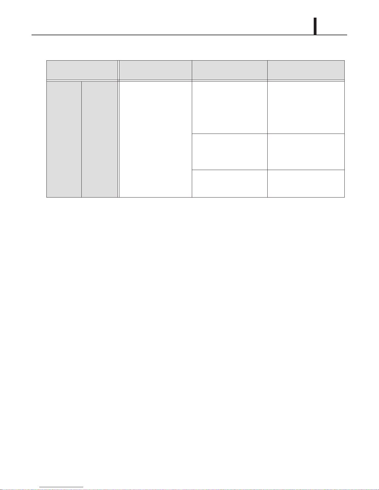
Troubleshooting of Unit does not operate - Table 2
Repair Section
63
Condition Check Area/Diagnostic
Unit does
not operate.
LCD
displays
self-
diagnostic
codes.
Possible Cause Remedy
Code
FL Drain tank is full of water. 1. Drain the water from the
tank.
2. Place the tank back in the
unit.
3. Press START/STOP
button to start.
Loose drain switch
connection.
Defective drain switch. 1. Replace the drain switch.
1. Reconnect the drain switch
and check connection.
2. Press START/STOP
button to start.
2. Press START/STOP
button to start.
Page 64

64
Repair Section
Troubleshooting of Unit does not operate - Table 3
Condition Check Area/Diagnostic
Unit does
not operate.
LCD
displays
self-
diagnostic
codes.
Possible Cause Remedy
Code
HP Operating outside of the
operating temperature
range.
Air flow is blocked or
restricted.
Loose high pressure switch
connection
1. Check operating
temperature and humidity
condition. Do not use the
unit outside the operating
condition range. (See page
13.)
2. Press and hold FAN+ and -
FAN buttons for 5 seconds
to reset.
1. Clean the air filters.
2. Ensure 24 inch (610 mm)
clearance in front of the
unit air inlets and air flow is
not blocked or restricted.
3. Press and hold FAN+ and -
FAN buttons for 5 seconds
to reset.
1. Reconnect the high
pressure switch and check
connection.
2. Press and hold FAN+ and
-FAN buttons for 5
seconds to reset.
Defective electronic
expansion valve
Defective high pressure
switch (short or open)
Refrigerant is over charged. 1. Charge correct amount of
1. Replace the electronic
expansion valve.
2. Press and hold FAN+ and
-FAN buttons for 5
seconds to reset.
1. Replace the high pressure
switch.
2. Press and hold FAN+ and
-FAN buttons for 5
seconds to reset.
refrigerant. (See page 95.)
2. Press and hold FAN+ and
-FAN buttons for 5
seconds to reset.
Page 65

Troubleshooting of Unit does not operate - Table 4
Repair Section
65
Condition Check Area/Diagnostic
Unit does
not operate.
LCD
displays
self-
diagnostic
codes.
Possible Cause Remedy
Code
AS Optional condensate pump
stops pumping water due to
any kinks and/or blockage in
the drain line or due to
improper routing of the drain
line.
Defective condensate pump 1. Repair or replace the
Missing or loose jumper
connector on the unit
without the condensate
pump
CF Defective compressor 1. Replace the compressor.
1. Remove any blockage or
kinks from the drain line or
improve hose installation.
2. Press and hold FAN+ and -
FAN buttons for 5 seconds
to reset.
condensate pump.
2. Press and hold FAN+ and -
FAN buttons for 5 seconds
to reset.
1. If the jumper connector is
in place, check connection.
If the jumper connector is
missing, insert the jumper
connector and check
connection.
2. Press and hold FAN+ and -
FAN buttons for 5 seconds
to reset.
2. Press and hold FAN+ and -
FAN buttons for 5 seconds
to reset.
E1 Loose RTS thermistor
connection
Defective RTS thermistor
(short or open)
E2 Loose ODS thermistor
connection
Defective ODS thermistor
(short or open)
E3 Loose CTS1 thermistor
connection
Defective CTS1 thermistor
(short or open)
Reconnect the RTS
thermistor and check
connection.
Replace the RTS thermistor.
Reconnect the ODS
thermistor and check
connection.
Replace the ODS thermistor.
Reconnect the CTS1
thermistor and check
connection.
Replace the CTS1
thermistor.
Page 66

66
Repair Section
Troubleshooting of Unit does not operate - Table 5
Condition Check Area/Diagnostic
Unit does
not operate.
LCD
displays
self-
diagnostic
codes.
LCD
displays
notification.
LCD shows
normal, but
the unit does
not start.
Possible Cause Remedy
Code
E4 Loose CTS2 thermistor
connection
Defective CTS2 thermistor
(short or open)
E5 Loose CTS3 thermistor
connection
Defective CTS3 thermistor
(short or open)
OUTSIDE OPERATING
RANGE
DEFROST Unit is under defrost control. Wait until defrost control is
KEY LOCKED Buttons on the control panel
EXTERNAL THERMOSTAT
ACTIVATED
Set point temperature Room temperature
Unit is operating outside
operating range.
are locked.
Status is changed to control
by an external thermostat.
reached the set point
temperature and the unit
operation stopped.
Reconnect the CTS2
thermistor and check
connection.
Replace the CTS2
thermistor.
Reconnect the CTS3
thermistor and check
connection.
Replace the CTS3
thermistor.
Check product specification
for temperature operating
range.
Press any key to exit.
completed.
Press and hold MENU/ESC
button for 5 seconds to
unlock.
Operate the unit by an
external thermostat.
Adjust the set point
temperature.
Fan on-off relay on the relay
board
Fan speed change relay on
Unit stops
immediately
after
starting.
LCD
displays
normally.
the relay board
Fan motor insulation
resistance
Compressor relay on the
relay board
Compressor insulation
resistance
Open circuit or insufficient
contact surface area
Open circuit or insufficient
contact surface area
Insulation failure on the fan
motor
Open circuit or insufficient
contact surface area
Insulation failure on
the compressor
Replace the relay board.
Replace the relay board.
Replace the fan motor.
Replace the relay board.
Replace the compressor.
Page 67

Troubleshooting of Unit does not operate - Table 6
Condition Check Area Possible Cause Remedy
Temperature of fan motor
(abnormally high)
Temperature of
compressor (abnormally
high)
Unit stops
after
running for
a while.
LCD
displays
normally.
Refrigerant leakage Insufficient refrigerant or gas
Activation of the internal
overload relay (IOLF) due to
fan motor malfunction
Activation of the overload
relay (IOLC) due to the
defective overload relay
Activation of the overload
relay (IOLC) due to the
defective compressor
leakage
Repair Section
67
Replace the fan motor.
Inspect the overload relay. If
defective, replace it.
Inspect the compressor. If
defective, replace it.
Repair and charge
refrigerant.
Dirt on indoor or outdoor
heat exchanger
Duct connection state Improper connection Repair duct connection.
(3) Overflow of drain water
Condition Check Area Possible Cause Remedy
Indoor or outdoor drain pan Cracks in the drain pan Check and replace the
Drain hole of the indoor or
Overflow of water from the
unit
outdoor drain pan
Clogged air filter Reversed air flow from the
Insufficient cooling or
heating of the heat
exchanger
Clogged drain hose Check and repair the
drain hole due to excessive
negative pressure inside of
the unit
Clean the heat exchanger.
drain pan.
drain hose.
Clean the air filter.
Page 68

68
Repair Section
(4) Abnormal noise or vibration
• To prevent abnormal noise or vibration, carefully determine the source of the problem and come
up with proper countermeasures to solve the problem so that it does not occur again.
Condition Check Area Possible Cause Remedy
Indoor or outdoor fan Fan interference Repair the interfering
Abnormal noise or
vibration
Compressor nuts Loose nuts Tighten the nuts.
Piping Pipe interference Repair the interfering
Panel fixing screws Loose screws Tighten the screws.
8.4 Basic Inspection
• Perform the following inspection before disassembly.
section.
Fan deformation Replace the fan.
section.
(1) Inspection of plate fins
• To inspect the plate fins of either the indoor or
outdoor heat exchanger, the air filter must be
removed. After removal of the air filters, inspect
the plate fins for any dirt, dust, lint, or debris
that may have caused insufficient cooling or
heating performance of the unit. If cleaning of
the fins is necessary, it is recommended that
this service be performed by a qualified service
technician.
(2) Examination of operating environment
• Operating environments can vary depending on location, climate and surrounding conditions.
Installation location also can cause operational problems. Consult your dealer concerning
operational environment requirements.
I001780
Page 69

Repair Section
ILL00890-00
Thermometer
Thermometer
Cool/Hot Air Out
Indoor Air In
(3) Inspection of cooling or heating performance
• Measure the difference in temperature between the inlet of the indoor heat exchanger and the
cool/heat air vent. If the difference is out of the range given in the graphs on page 19 and 24,
proceed with the remedy suggested in the troubleshooting chart on page 59 to 61.
69
Page 70

70
ILL00891-00
Left Panel
Front Cater
Rear Caster
Power Cord
Indoor Drain Pan
Outdoor Drain Pan
Drain Tank Cover
Divider Panel for
Outdoor Heat
Exchanger
Drain Tank
Air Outlet Grill
Right Filter Panel
Wire Frame
Top Panel
Right Handle
Upper Front Panel
Control Panel
Drain Tank Base Plate
Service Panel
Drain Switch Wire
Right Panel
Front Filter Panel
Air Filter
Rear Panel
Left Handle
Wire Frame
Blower Assembly
(Indoor Heat Exchanger)
Air Filter
Blower Assembly
(Outdoor Heat Exchanger)
Repair Section
9. DISASSEMBLY
WARNING
• Disconnect power supply from the unit before performing any service. Beware that some
residual voltage may remain in the unit immediately after the power is disconnected.
9.1 Unit Parts Construction
Page 71

9.2 Removal of Panels
ILL00892-00
Screw (1)
Screw (1)
Screws (2)
ILL00893-00
I002206
Tabs
Pivots
Repair Section
71
1) Remove the drain tank.
I002203
2) Remove four (4) screws from the upper front
panel.
3) Slide the upper front panel forward and remove.
4) Louver can be removed from the upper front
panel by unsnapping the lock tap and removing
the louver from its pivots.
Page 72

72
ILL00894-00
Screws (7)
ILL00895-00
Screws (7)
Screws (2)
ILL00896-00
Screws (2)
Screws (3)
Screws (2)
Screws (3)
ILL00897-00
Screws (4)
Screws (2)
Screws (2)
Repair Section
5) Remove seven (7) screws from the service
panel.
6) Remove nine (9) screws from the rear panel.
7) Remove eight (8) screws from the rear panel and
two (2) screws from the outdoor fan casing.
8) Remove eight (8) screws from the left panel.
Page 73

Repair Section
ILL00898-00
Screws (3)
Screws (4)
Screws (3)
9) Remove ten (10) screws from right panel.
73
Page 74

74
ILL00863-00
Terminal Block 1 (For Power)
Relay Board
Relay Board Fuse (F2)
(1 A, 250 V)
Terminal Block 2
(For Input/Output Signal)
Terminal Block 3
(For External Thermostat)
Fuse (F1)
(1.5 A, 250 V for
4-Way Valve,
Drain Pan Heater of
Outdoor Heat Exchanger)
Compressor Motor
Capacitor
Transformer (For Relay Board)
Fan Motor Capacitor
<Service Box>
Repair Section
9.3 Removal of Electrical Parts
WARNING
• Disconnect power supply from the unit before performing any service. Beware that some
residual voltage may remain in the unit immediately after the power is disconnected.
(1) Service box
1) Remove seven (7) screws from the service panel. (See page 72.)
2) Remove the electrical parts.
- Fuse 1: Remove one (1) screw from the control box.
- Fan motor capacitors: Remove two (2) screws from the control box.
- Compressor motor capacitor: Remove two (2) screws from the control box.
- Terminal block 1: Remove two (2) from the control box.
- Terminal block 2: Remove two (2) from the control box.
- Terminal block 3: Remove two (2) from the control box.
- Transformer: Remove two (2) from the control box.
Page 75
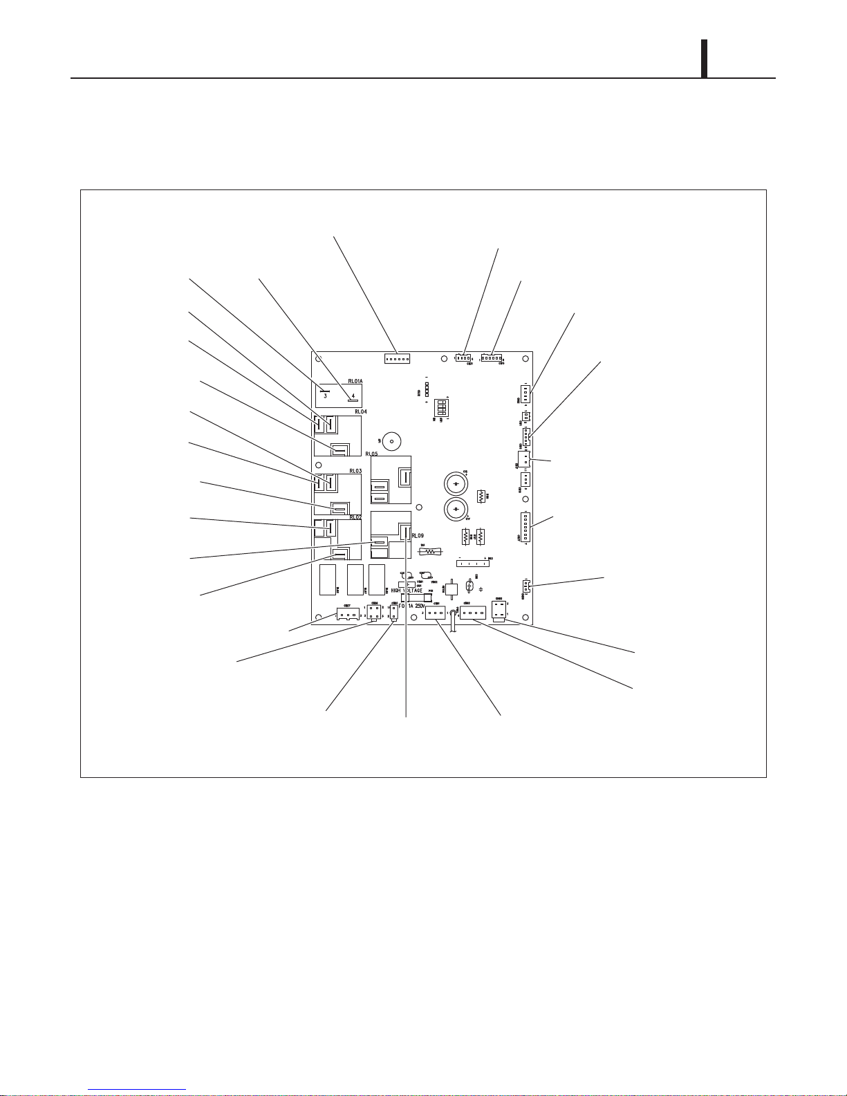
(2) Relay board
ILL00899-00
CN17: To Optional Condensate Pump
CN37: To Electronic Expansion Valve
CN30: Control Panel Board
CN03: To Transformer
CN02: To Transformer
CN01: To Terminal Block 1
(#R, T for Power)
RL09-COM
CN18: To Drain Switch,
High Pressure Switch
CN14: To ODS, CTS2, CTS3 Thermistors
CN12: To RTS, CTS Thermistors
CN31: To Terminal Block 2
(#GND, Rx, Tx, +5V for Serial Communication Port)
CN34: To Terminal Block 3 for Millivolt,
24VAC thermostat
RL01A-4
RL01A-3
RL04-NO
RL04-NC
RL04-COM
RL03-NO
RL03-NC
RL03-COM
RL02-NO
RL02-COM
CN27: To Outdoor Drain Pan Heater
CN25: To 4-Way Valve
CN26: To Terminal Block 2
(#OS-1, OS-2 for Warning Device)
RL09-NO
1) Remove nine (9) supports from the service panel. (See page 72.)
2) Disconnect twenty six (26) connectors from the relay board.
Repair Section
75
Page 76

76
ILL00912-00
Screws (2)
Screws (2)
ILL00900-00
CN2 Connector
Repair Section
(3) Control panel
1) Remove four (4) screws from the control panel
stay.
2) Disconnect the CN2 connector from the control
board.
Page 77

Repair Section
ILL00902-00
Old Battery
Holder
<Control Board>
ILL00903-00
Holder
<Control Board>
New Battery
(4) Battery replacement of control board
• If the clock is reset to initial setting "SUN 12:00AM" when the unit is powered on, it is time to
replace the battery on the control board.
1) Remove the old battery from the holder.
2) Insert new battery securely in the direction shown
in the diagram.
77
Specifications:
- Type: 3 V CR2032
CAUTION
When inserting the battery, make sure the
direction of polarity (plus/minus) is correct as
shown.
Page 78
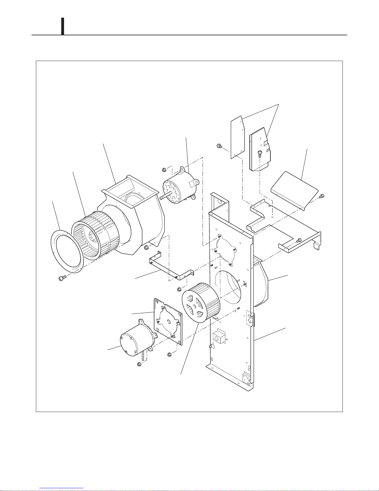
78
ILL00901-00
Outdoor Fan Casing
Stay for Control Panel
Indoor Wind
Direction Stay
Indoor Fan Casing
Center Panel
Indoor Fan Motor
Indoor Fan
Stay for Indoor Fan Motor
Outdoor Fan Motor
Stay for Outdoor
Fan Casing
Outdoor Fan
Ring
Repair Section
9.4 Removal of Blower Assembly
Page 79

(1) Removal of outdoor fan and motor
ILL00907-00
Ring
Outdoor Fan Casing
Screws (3)
Outdoor Fan
Nuts (2)
Nuts (2)
Set Screw
ILL00908-00
Outdoor Fan Motor
Nuts (4)
Repair Section
79
1) Remove three (3) screws and take out the ring.
2) Loosen the set screw using a hex key. Then remove the outdoor fan.
3) Remove four (4) nuts and remove the outdoor fan casing.
4) Remove four (4) nuts and remove the outdoor fan motor.
Page 80

80
ILL00909-00
Indoor Fan Motor
Indoor Fan
Motor Stay
Nuts (4)
Nuts (4)
Set Screw
Repair Section
(2) Removal of indoor fan and motor
1) Remove four (4) nuts from the motor stay and take out the motor stay together with the indoor
fan and motor.
2) Loosen the set screw using a hex key. Then remove the indoor fan.
3) Remove four (4) nuts from the motor stay and remove the indoor fan motor.
9.5 Inspection of Capacitor (for Fan Motor and Compressor)
(1) Ohmmeter method
• Set the ohm-meter to the 10M range. Place the
two probes against the two terminals of the
capacitor. At first, the ohm-meter should
indicate small value, then the reading should
gradually increase towards infinity. This
indicates that the capacitor is charging. If the
reading indicates infinity right away (open) or
the ohm-meter fails to move from 0. (shorted),
replace the capacitor.
I001808
Page 81

Repair Section
ILL00904-00
2
NC
C
1
DS2
DS1
To CN18
Drain Switch
Top of Base Plate
ILL00866-00
CF1-1 (White)
CF1-2 (White/Brown)
RL03-NC (H) (Black)
RL03-NO (M) (Red)
RL04-NO (L) (Blue)
Ground
(Green/Yellow)
(2) Capacitance tester method
• Using a capacitance tester and the chart on page 35, test the capacitor for the value indicated.
If the value tested is not within 10 % of indicated capacitance, replace the capacitor.
WARNING
• Properly discharge the capacitor(s) before testing and after testing has been completed.
• Failure to do so could cause damage to test equipment or the unit and/or result in
personal injury (electrical shock) or death.
9.6 Inspection of Drain Switch
• Check for continuity between terminals 1 and 2
when drain switch is pressed. With drain switch
depressed, there is no continuity between
81
terminals 1 and 2. Replace drain switch if
continuity does not satisfy the above condition.
9.7 Inspection of Fan Motor
(1) Indoor fan motor
• Check resistance across the terminals of the
fan motor. (All terminals must be disconnected
from the unit.)
- High resistance between CF1-1 and CF1-2
- Medium resistance between CF1-2 and
RL03-NC (H)
- Low resistance between CF1-1 and RL03-
NC (H)
• If the resistance reading does not meet the
above conditions, replace the fan motor.
Page 82

82
ILL00867-00
CF2-1 (White)
CF2-2 (White/Brown)
Ground
(Green/Yellow)
RL09-NO (Black)
I002249
C
S
R
I001701
Repair Section
(2) Outdoor fan motor
• Check resistance across the terminals of the
fan motor. (All terminals must be disconnected
from the unit.)
- High resistance between CF2-1 and CF2-2
- Medium resistance between RL09-NO and
CF2-2
- Low resistance between RL09-NO and CF2-
1
• If the resistance reading does not meet the
above conditions, replace the fan motor.
9.8 Inspection of Compressor
(1) Compressor motor
• Check resistance across the terminals of the
compressor motor. (All terminals must be
disconnected from the unit.)
- High resistance between S (Start) and R
(Run)
- Medium resistance between S (Start) and C
(Common)
- Low resistance between R (Run) and C
(Common)
• If the resistance reading does not meet the above conditions, replace the compressor.
(2) Overload relay
• Check for continuity across two terminals of the
overload relay. At normal temperature, there
should be continuity across the terminals.
Operating Temperature
OFF (open contacts) ON (closed contacts)
302 °F (150 °C)
• If there is no continuity across the terminals,
replace the overload relay.
156 °F (69 °C)
Page 83

9.9 Inspection of Transformer
ILL00879-00
Secondary
20 V
<Wiring Diagram>
40 VA, 60 Hz
1
5
10
6
4
2
Primary
115 V
ILL00905-00
Secondary
Primary
Connected to
Signal Terminals
(24VAC Neutral,
24VAC Hot)
40 VA, 60 Hz
Connected to
Terminals
(R1, T1)
3
10
6
120 V 24 V
3
5
10
6
<Wiring Diagram>
(1) Transformer for relay board
• Check resistance across the terminals of the
transfomer for the relay board. (All terminals
must be disconnected from the unit.) Primary
resistance value should be between 10 to 50
times larger than the secondary resistance
value.
• If the resistance reading does not meet the
above condition, replace the transformer.
(2) Transformer (optional) for 24VAC thermostat (field supplied)
• Check resistance across the terminals of the
Repair Section
83
transformer for the 24VAC thermostat. (All
terminals must be disconnected from the unit.)
Primary resistance value should be between
10 to 50 times larger than the secondary
resistance value.
• If the resistance reading does not meet above
condition, replace the transformer.
Page 84

84
ILL00906-00
76543
21
Connector Number
Wire Color
1 Red
2 Blue
3 Orange
4 Yellow
5
6
7
White
Not in use
Not in use
ILL00862-00
I003204
Repair Section
9.10 Inspection of Electronic Expansion Valve Control Coil
• Check resistance across the connector pins of
the electronic expansion valve control coil. Coil
resistance should be between 26 to 56 ohm at
room temperature.
- Between Blue and Red
- Between Orange and Red
- Between Yellow and Red
- Between White and Red
• If the resistance reading does not meet the
above condition, replace the electronic
expansion valve control coil.
9.11 Inspection of 4-Way Valve Controller Coil
• Check resistance across the connector pins of
the 4-way valve controller coil. Coil resistance
should be between 350 to 520 ohm at room
temperature.
• If the resistance reading does not meet the
above condition, replace the 4-way valve
controller coil.
9.12 Inspection of Thermistor
• Using an ohmmeter, check the resistance
value across the 2-pin connector.
• Thermistors:
- Indoor air inlet thermistor (RTS)
- Outdoor air inlet thermistor (ODS)
- Indoor pipe thermistor (CTS1)
- Compressor pipe thermistor (CTS2)
- Outdoor pipe thermistor (CTS3)
20
Thermistor Specification
15
10
5
Resistance (k ohm)
0
32
(0)41(5)50(10)59(15)68(20)77(25)86(30)95(35)
Temp.°F (°C)
104
(40)
133
(45)
122
(50)
Page 85

Repair Section
9.13 Inspection of Wiring Connection
• Refer to the wiring diagram on page 33 and check the connection of each wire.
CAUTION
Secure the wires using clamps to prevent contact with the edges of the structure, etc. Secure the
wires in the same position as prior to removal.
9.14 Inspection of Refrigeration System
• In most cases, the probable cause for insufficient cooling or heating is a clog in the system, a
leakage or an incorrect amount of refrigerant. In such cases, inspect the system according to
the following procedure.
(1) Clogged refrigeration system
85
• Check the component parts of the refrigeration system, including piping, that could be clogged
with refrigerant. If clogged with refrigerant, only the clogged part is partially frosted. If this occurs,
change the part in question.
(2) Refrigerant leak
• Carefully check all connections, and each component for leaks whenever the refrigeration
system is installed or repaired. Use an electronic gas leak tester to inspect the system. (See "10.
REFRIGERATION SYSTEM REPAIR" section.)
(3) Insufficient refrigerant
• When the unit is not producing sufficient cooling or heating, follow the troubleshooting chart on
page 60 to page 61 to confirm the cause of the problem. Then, charge the system with
refrigerant to the specified amount as indicated on page 95.
Page 86

86
I002225
Clearance
Clearance From The Pipe Fitting and Tubing.
0.001~0.003 in
(0.025~0.075 mm)
a
a
Repair Section
10. REFRIGERATION SYSTEM REPAIR
10.1 Repair of Refrigeration System
• In case there is a leak, obstruction, or problem in the refrigeration system of this unit, replace or
repair the part in question. After replacing any component, all connections must be brazed.
(1) Proper brazing techniques
• It is desirable to use a slightly reduced flame. Oxyacetylene is commonly used since it is easy
to judge and adjust the condition of the flame. Unlike gas welding, a secondary flame is used for
brazing. It is necessary to preheat the base metal properly depending on the shape, size or
thermal conductivity of the brazed fitting.
• The most important point in flame brazing is to bring the whole brazed fitting to a proper brazing
temperature. Care should be taken not to cause overflow of brazing filler metal, oxidization of
brazing filler metal, or deterioration due to the overheating of flux.
(2) Brazed fittings and fitting clearance
• In general, the strength of brazing filler metal is
lower than that of the base metal. So, the
shape and clearance of the brazed fitting are
quite important. As for the shape of the brazed
fitting, it is necessary to maximize its adhesive
area. The clearance of the brazed fitting must
be minimized to facilitate brazing filler metal to
flow into it by capillary action.
(3) Cleaning brazing filler metal and pipe
• When the refrigeration system has been opened up, exposure to heat may have caused brazing
filler metal to stick to the inside and outside of the pipe. Brazing filler metal may also be
compounded with oxygen in the air to form oxide film. Fats and oils may stick to the pipe from
handling. All these factors can reduce effectiveness of brazing. It is necessary to eliminate
excess brazing filler metal using sand paper and by cleaning thoroughly with a solvent such as
trichlene.
CAUTION
Do not use chlorine cleaner.
Page 87

Repair Section
< NOTE >
I000564
Burner
45°
Tube
Brazing Filler Metal
Vertical Down Joint
I001725
Burner
45°
Tube
Brazing Filler Metal
Vertical Up Joint
(4) Use of dry nitrogen gas
• During brazing, the inside of the pipe undergoes an oxidative reaction due to the brazing flame.
Introduce dry nitrogen gas (0.27 gal/min (1 L/min); adjust with the flow regulator) through the
pinch-off tube of the refrigerant.
Take care not to allow dirt, water, oil, etc. to enter into the pipe.
(5) Vertical Joint
• Heat the whole brazed fitting to a proper
brazing temperature. Bring the brazing filler
metal into contact with the fitting so that the
brazing filler metal starts flowing by itself.
• Stop heating the fitting as soon as the brazing
87
filler metal has flown into the clearance. Since
the brazing filler metal flows easily into the
portion heated to a proper temperature, it is
essential to keep the whole fitting at a proper
brazing temperature.
Page 88

88
< NOTE >
ILL00910-00
Compressor A, B
A, B, C, D
C, F, G, H
N, O
C, D
E
Indoor Heat Exchanger
Outdoor Heat Exchanger
High Pressure Switch
Electronic Expansion Valve
Distributor
Part to Replace Disconnect At
C
Pipe 1
Pipe 2
E
B
Tube 2
N
Tube 1
O
A
D
F
G
H
Repair Section
10.2 Removal of Refrigeration Cycle Components
WARNING
• Before replacing any refrigeration cycle component, recover the refrigerant using
standard recovery procedures and equipment.
• When recovering the refrigerant, use the pinch-off tubes at the low pressure side (tube 1)
and high pressure side (tube 2) as shown in the figure below.
CAUTION
• To prevent oxidation, dry nitrogen should be conducted (flow rate 0.27 gal/min (1 L/min)) through
the pinch-off tube during any brazing operation.
• During any component replacement involving brazing, shield nearby parts with a steel plate, etc.,
to protect them from the flame.
When replacing the compressor, attach the pipe 1 and the pipe 2 packaged in the compressor
assembly.
Page 89

Repair Section
ILL00914-00
I, J, K, L
M
(Remove one screw.)
P
(Pull up from the clip.)
Part to Replace Disconnect At
Electronic Expansion
Valve Controller
4-Way Valve
4-Way Valve Controller
Pipe Assembly D, Q, R, S
A, B, D, T
C, U
Pipe Assembly with High
Pressure Switch and
4-Way Valve
Pipe Assembly with
Electronic Expansion Valve
C
B
M
L
I
K
J
T
P
Q
R
S
A
D
U
89
Page 90

90
ILL00084-00
Step 1
Step 5
Step 6
Step 4
Step 3
Step 2
Connect manifold gauge.
1) Evacuate the system.
• 15 minutes or more.
• 30 inHg (100 kPa) or more of vacuum.
2) Stop evacuating the system.
• Leave for 5 minutes.
3) Check the vacuum.
When leak is found,
repair the connection
or components.
Charge the system with R-410A.
• See “Technical Specifications” for the specified amount.
Remove manifold gauge.
Test the system for leaks.
Connect to refrigerant source.
Repair Section
10.3 Charging the System with R-410A Refrigerant
• Always ensure that the refrigeration system has been properly evacuated before charging with
the specified amount of R-410A.
• Equipments is only for R-410A.
• Liquid charge (no gas charge).
• Make sure not to use more than 90 % of the initial weight of R-410A in the cylinder.
WARNING
• When handling refrigerant (R-410A), the following precautions should always be
observed:
- Always wear proper eye protection while handling refrigerant.
- Maintain the temperature of the refrigerant container below 104 °F (40 °C).
- Perform repairs in a properly ventilated area. (Never in an enclosed environment.)
- Do not expose refrigerant to an open flame.
- Never smoke while performing repairs, especially when handling refrigerant.
- Take caution so that the liquid refrigerant does not come in contact with the skin.
• If liquid refrigerant strikes eye or skin:
- Do not rub the eye or the skin.
- Splash large quantities of cool water on the eye or the skin.
- Apply clean petroleum jelly to the skin.
- Go immediately to a physician or to a hospital for professional treatment.
Page 91

(1) Connection of gauge manifold
< NOTE >
I002183
Pinch-Off Tube
Seal
Charging Hose
Side
Refrigerant
Cycle Side
I000568
High Pressure Valve
(Closed)
High Pressure
Side Tube
Vacuum Pump
(when stopped)
Low Pressure
Valve (Closed)
Red Hose
Green Hose
Process Tube Fitting
I002227
LO
ClosedHIOpenLOClosedHIClosed
Valve Setting
30 inHg (100 kPa) or larger
High Pressure Valve
High Pressure Gauge
Gauge
High Pressure
Side Tube
Vacuum Pump
(in Operation)
Low Pressure
Val ve
Repair Section
91
1) Properly remove the crushed end of the pinch-off
tube at the high pressure side and the low
pressure side of the refrigerant cycle with a pipe
cutter.
2) Fit the process tube fitting to the pinch-off tube on
both sides.
3) Connect the charging hoses (red-high pressure
side) for the gauge manifold to the process tube
fitting.
(2) Evacuation
Connect the hoses using care not to mistake
the high pressure side for the low pressure side
and vice versa.
4) Connect the charging hose (green) at the center
of the gauge manifold to the vacuum pump.
1) Open the high pressure valve (Hl) of the gauge
manifold.
2) Turn on the vacuum pump to start evacuation.
(Evacuate the system for approximately 15
minutes.)
3) When the low pressure gauge indicates 30 inHg
(100 kPa) or larger, turn off the vacuum pump
and close the high pressure valves of the gauge
manifold.
Page 92
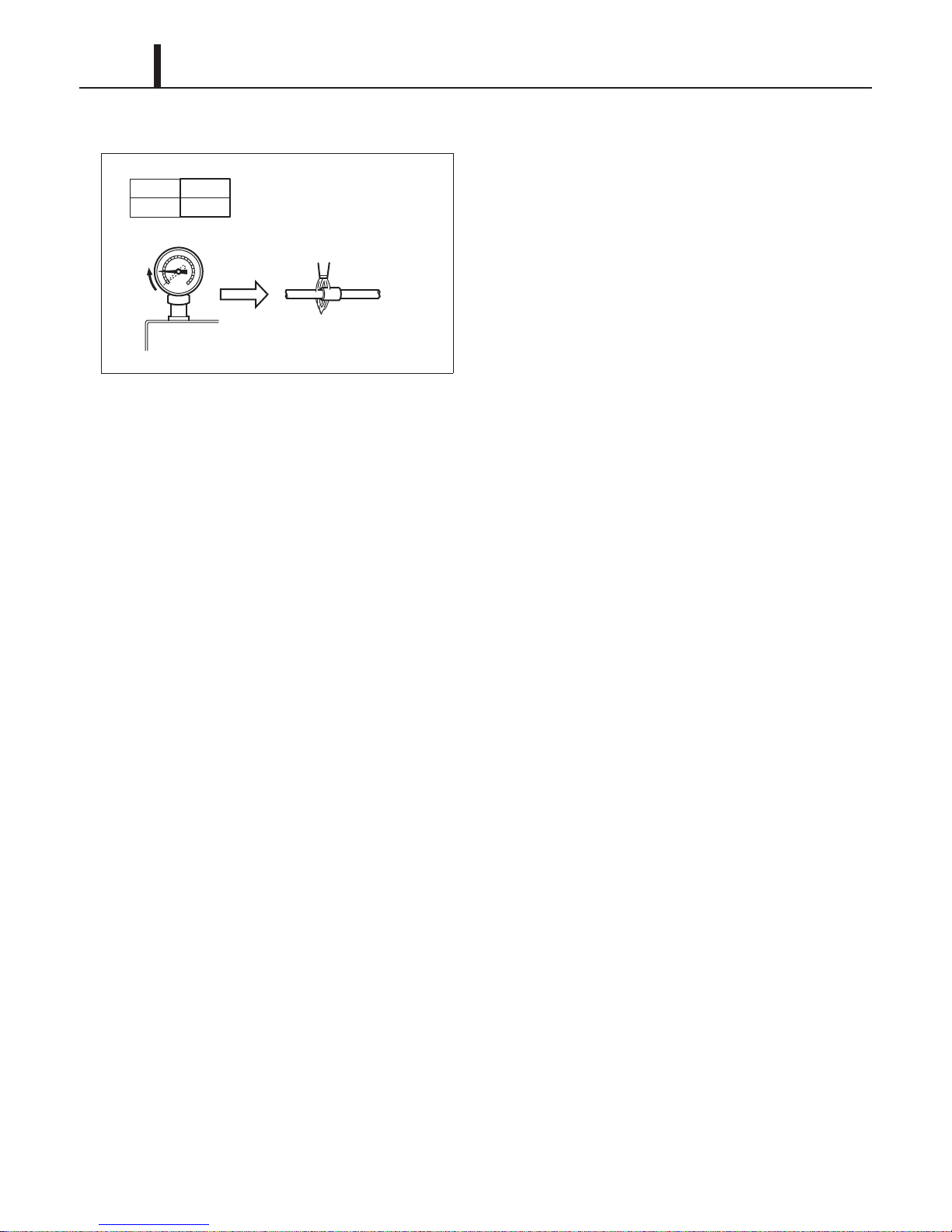
92
ILL00085-00
Return
Pipe Brazing
LO
ClosedHIClosed
Valve Setting
Pressure Gauge
Repair Section
(3) Checking vacuum
1) Leave the high pressure valve and the low
pressure valve of the gauge manifold closed for 5
minutes or more, and confirm that the gauge
pointer does not return to zero.
2) If the gauge pointer returns gradually to zero
there is a leak somewhere in the system (this
could also include gauge manifold). Perform leak
check according to procedure indicated in the
next step. Once leak has been found and
repaired, evacuate the system once more and
confirm the system holds vacuum.
Page 93

(4) Checking gas leak
I001901
Open The Valve
of Refrigerant
Cylinder
To Process Tube Fitting
Charging Hose
(Green)
Refrigerant
Cylinder R-410A
Red
LO
ClosedHIClosed
Valve Setting
Air Purging
I002228
LO
ClosedHIOpen
LO
ClosedHIClosed
Refrigerant
Cylinder R-410A
Valve Setting
Gauge Reading
57 psi
(390 kPa)
Open High Pressure
Val ve
High Pressure
Side Tube
Low Pressure
Valve (Closed)
Process Tube Fitting
Refrigerant
Cylinder
Val ve
(Open)
Repair Section
93
1) Remove the charging hose (green) from the
vacuum pump, and connect the hose to the
refrigerant cylinder (R-410A).
2) Loosen the nut on the gauge manifold side of the
charging hose (green).
3) Open the valve of refrigerant cylinder and
perform air purging in the charging hose (green).
Then tighten the nut.
4) Open the high pressure valve of the gauge
manifold. Charge the system with refrigerant until
the low pressure gauge indicates 57 psi
(0.39 kPa). After charging is complete, close the
high pressure valve.
5) Open the valve of refrigerant cylinder and
perform air purging in the charging hose (green).
Then tighten the nut.
6) Check carefully for gas leaks inside the
refrigeration system using the gas leak tester.
7) Repair any leak.
WARNING
Any repair on a charged system should be
performed by a licensed professional only.
WARNING
Before checking for gas leaks, fully confirm
that there is nothing flammable in the area
to cause an explosion or fire. Contact of
refrigerant with an open fire generates
toxic gas.
Page 94

94
< NOTE >
I002227
LO
ClosedHIOpenLOClosedHIClosed
Valve Setting
30 inHg (100 kPa) or larger
High Pressure Valve
High Pressure Gauge
Gauge
High Pressure
Side Tube
Vacuum Pump
(in Operation)
Low Pressure
Val ve
Repair Section
(5) Evacuation (repeat)
1) Close the valve of the refrigerant cylinder. Then
remove the charging hose (green) from the
refrigerant cylinder, and connect it to the
refrigerant recovery machine.
Keep the high pressure valve and the low
pressure valve of the gauge manifold closed.
2) Using procedure in the “Evacuation”, evacuate
the system until the low pressure gauge indicates
30inHg (100 kPa) or larger. (For 15 minutes or
more.)
3) After evacuation is complete, close the high and
the low pressure valves of the gauge manifold.
CAUTION
Make sure to evacuate the system twice or
more using the repetitive vacuum method.
Evacuate the system an additional time on
rainy or humid days.
Page 95

10.4 Refrigerant Charging Work
I001901
Open The Valve
of Refrigerant
Cylinder
To Process Tube Fitting
Charging Hose
(Green)
Refrigerant
Cylinder R-410A
Red
LO
ClosedHIClosed
Valve Setting
Air Purging
I001903
LO
ClosedHIOpen
LO
ClosedHIClosed
Refrigerant
Cylinder R-410A
Valve Setting
Specified Amount
of Refrigerant
High Pressure Valve
High Pressure
Side Tube
Process Tube Fitting
Valve of
Refrigerant
Cylinder
Weight
(1) Refrigerant charging
Repair Section
95
1) Remove the charging hose (green) from the
vacuum pump, and connect it to the refrigerant
cylinder
(R-410A).
2) Loosen the nut on the gauge manifold side of the
charging hose (green). Open the valve of the
charging hose (green). Open the valve of the
refrigerant cylinder. After air purging, tighten this
nut and close the valve of the refrigerant cylinder.
3) Securely place the refrigerant cylinder on a scale
with a weighing capacity of 70 lb (30 kg) that is
graduated by 0.2 oz (5 g).
4) Open the high pressure valve of the gauge
manifold and the valve of the refrigerant cylinder.
Charge the system with refrigerant to the
specified amount.
Standard Amount of Refrigerant:
1.94 lb (0.88 kg)
CAUTION
The amount of refrigerant charged has a great
effect on the cooling and heating capacity of
the unit. Charge to the specified amount,
always observing the scale graduations while
charging.
5) Close the high pressure valve of the gauge
manifold and the valve of the refrigerant cylinder.
Page 96

96
I002185
Pinch-Off Tube
Pinch-Off Tool
Process Tube Fitting
Charging Hose
To Gauge
Manifold Side
To Refrigerant
Cycle Side
Repair Section
(2) Removal of gauge manifold
1) Crimp the pinch-off tube with a pinch-off tool.
2) Remove the gauge manifold and the process
tube fitting. Crush the end of the pinch-off tube.
3) Braze the end of the pinch-off tube.
4) Ensure that a gas leak is not present at the
pinched off portion and the brazed end.
Page 97

Repair Section
ILL00178-00
Nut
Steel Collar
Cushion
Plate Washer
ILL00913-00
Set Screw
11. REASSEMBLY
11.1 Removal of Unit
• Reassemble the unit in the reverse order of removal. Described below are the parts that require
special care in reassembling the unit. Perform all wiring or rewiring as referenced in the wiring
diagram.
11.2 Compressor Mounting
• Mount the compressor on the frame, using
cushions, steel collars, plate washers and nuts.
97
11.3 Blower Assembly
11.4 Wiring Notice
• Secure the wires using clamps so that they do not come into contact with the edges of the
structure. Secure the wires using clamps in the same position they were before removal.
• Tighten the set screws of indoor and outdoor fans
at the torque shown below.
CAUTION
• Tightening torque:
- 10.84 ± 2.17 ft•lbf (15 ± 2.7 N•m)
Page 98

98
< NOTE >
Repair Section
11.5 Perform the Inspection
• Perform the inspection of cooling and heating performance and check for abnormal noise or
vibration.
11.6 Caster Maintenance
• Lubricate bearings in caster as needed with standard bearing grease using the zerk fitting.
Casters should roll and swivel freely. Check for dirt or dust build up. Remove dust or dirt build up.
Page 99

P/N: SV0082-00
First Issue: December 2014
 Loading...