

Page 1
MANUAL
U
L
US LISTED
C
Page 2

This warranty does not cover defects or malfunctions which result from causes
The aforesaid warranty is the only warranty made by DENSO with respect to the
tial, incidental, special or exemplary damages of any kind. DENSO DISCLAIMS
ALL OTHER WARRANTIES WITH REGARD TO THE PRODUCTS, INCLUDING
ALL IMPLIED WARRANTIES OF MERCHANTABILITY AND FITNESS FOR USE.
THERE ARE NO WARRANTIES WHICH EXTEND BEYOND THE DESCRIPTION
______________________________________________________
______________________________________________________
All rights reserved. This book may not be reproduced or copied,
Page 3

....................................................
.............................................................................................
..........................................................
................................................................................
...............................................................................................
............................................................................................
................................................................
.....................................................................
.............................................................................
.......................................................................................
....................................................................
.......................
.............................................................................
AFCI Power Cord
...........................................................................
Page 4

This manual explains how to assemble, install and operate the MovinCool Offi ce Pro 36
yourself with the features of the unit and to ensure years of reliable operation. You may
WARNING: Describes precautions that should be observed in order to prevent
injury to the user during installation or unit operation.
CAUTION: Describes precautions that should be observed in order to prevent
damage to the unit or its components, which may occur during installation or unit
operation if suffi cient care is not taken.
NOTE: Provides additional information that facilitates installation or unit operation.
the power cord causing electrical shock or fi re.
Page 5
CAUTION: Following are some precautions to consider before choosing your installation site. Please review carefully as improper installation may result in personal
injury or damage to the unit.
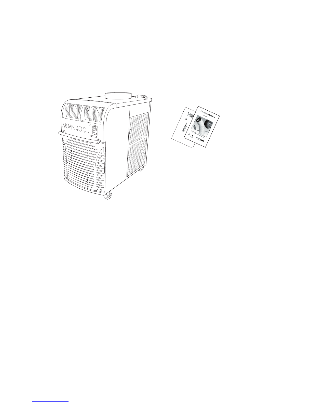
After unpacking your MovinCool unit, please check to make sure you have the following
NOTE: If any of these items were not included in the box or appear damaged, please
contact your MovinCool reseller for replacement.
OPERATION MANUAL/
WARRANTY CARD
3
6
Page 6
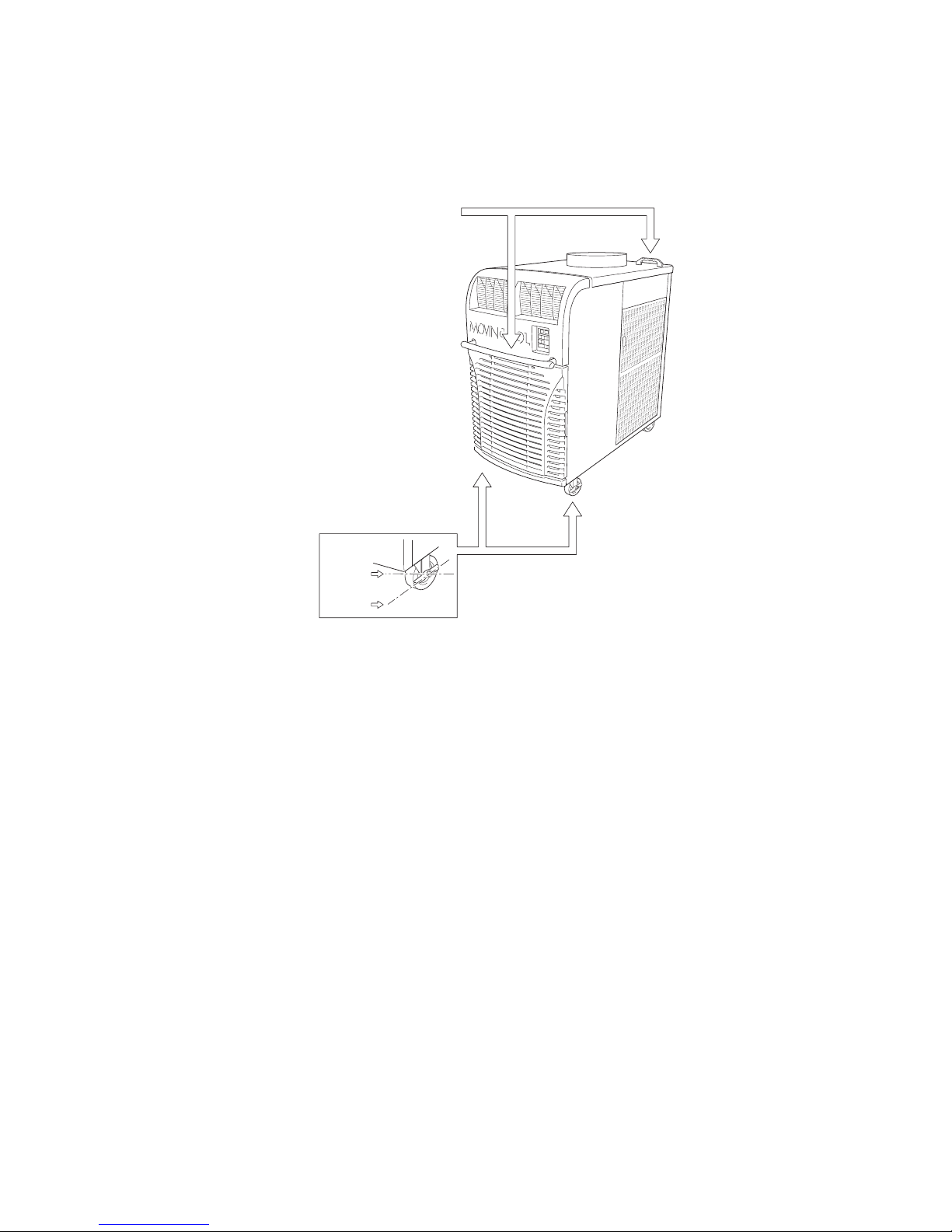
UNLOCKED
LOCKED
FRONT AND BACK HANDLES
WARNING:
• If the power cord or plug is damaged, repair should only be performed by qualifi ed electrical personnel.
• Do not connect/disconnect the power cord or attempt to operate buttons with
wet hands. This could result in electrical shock.
CAUTION: The AC outlet (208/230 VAC Single Phase, 60Hz) needs to be rated at
30A or higher. Do not share the outlet with any other instrument or equipment.
NOTE:
Page 7
▼/▲
). (65ºF-95ºF)
to the operating mode it was in prior to the loss of power. Any preset program will be
time of day that the unit will begin to
O
/O
the C
mode/turns the unit off.
the HIGH or LOW fan mode.
▼/▲
) - Increases/decreas-
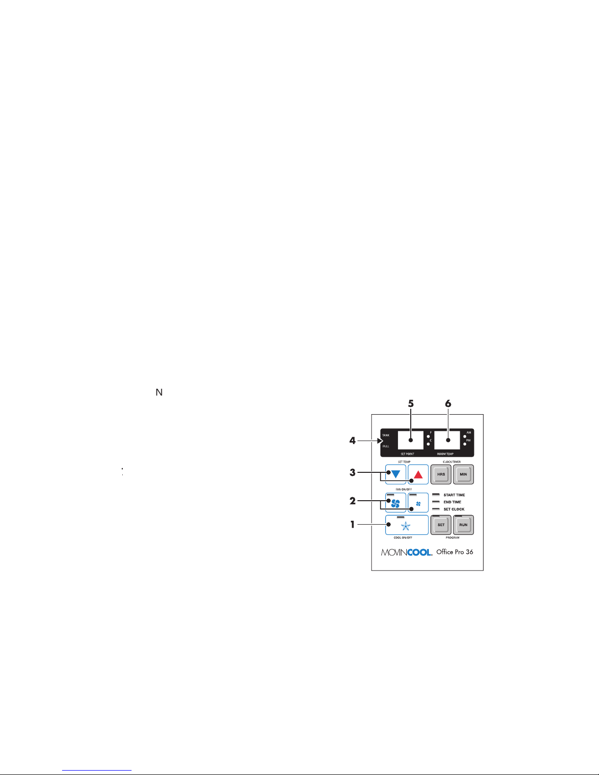
ANK FULL
LED - Flashes when the drain tank
Display - Indicates the current tem-
Display - Indicates the current
Page 8
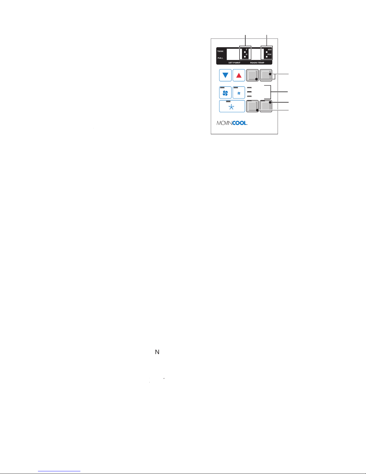
Temperature Scale LED - Illu
the current temperatures being displayed are
LED - Illuminates to indicate AM or PM
time of day.
Button - Activates/deactivates a
LED,
LED,
LED - Illuminates to indicate the cur-
Buttons - Allows the user to set the clock and program the start and
tion.
The unit can be operated in COOL mode by pressing the C
NOTE: In COOL mode the unit can only be turned off by pressing the “C
Change the fan speed by pressing the HIGH or LOW fan buttons.
Change the temperature set point by pressing the SET TEMP buttons (
▼/▲
).
NOTE: When turning the unit on, the set point and fan speed are determined by the
last operating mode (program mode not included).
The unit can also be operated in Fan Only mode by pressing either the HIGH or LOW
The unit can then be turned off by pressing the fan speed button that is illuminated.
The C
mode can be activated while the unit is operating in Fan Only mode. To do
this, simply press the C
O
/O
button (LED illuminates).
NOTE: The Fan Only mode will not operate after the C
mode has been activated.
After the COOL mode has been activated, the unit cannot be turned off by pressing
SET TEMP CLOCK/TIMER
FA
N ON/OFF
COOL ON/OFF PROGRAM
Office Pro 36
SET
START TIME
END TIME
SET CLOCK
RUN
HRS MIN
87
12
11
9
10
O
/O
button must be pressed.
Page 9

Setting a START TIME
Press the Program SET button. The Program SET button and START T
LEDs will
Setting an END TIME
Press the Program S
button until the E
LED illuminates. Press the HRS
Setting the CLOCK TIME
Press the Program S
button until the S
LED illuminates. Press the HRS
NOTE: The AM/PM LED will change with the HRS button.
Programming the Temperature SET POINT
Press the Program S
button until the current S
temperature display
temperature by pressing
the SET TEMP buttons (
▼/▲
).
Programming the Fan Speed
Press the Program S
button until one of the Fan Speed button LEDs (High/Low)
Exiting the Program SET Function
After changing any of the above settings, continue pressing the Program SET
Activating/Deactivating a Preset Program
LED will illuminate when activated.
NOTE:
running.
Program RUN button. All other buttons are inoperable when a program is run-
ning.
Page 10
Offi ce Pro 36 will operate in FAN Only mode for approximately 120 seconds before
the compressor engages. (Time delay setting is 120 ±15 seconds.)
The room temperature thermistor allows the unit to switch automatically between
The Fan Mode Control DIP Switch determines whether the FAN will continue to oper-
The Temperature Scale Display DIP Switch changes the temperature(s) that are
temperature(s) in °F.
NOTE: If you wish to change the fan mode operation (COOL
STOP), and/or the Temperature Scale Display (°F to °C), contact your Movin-
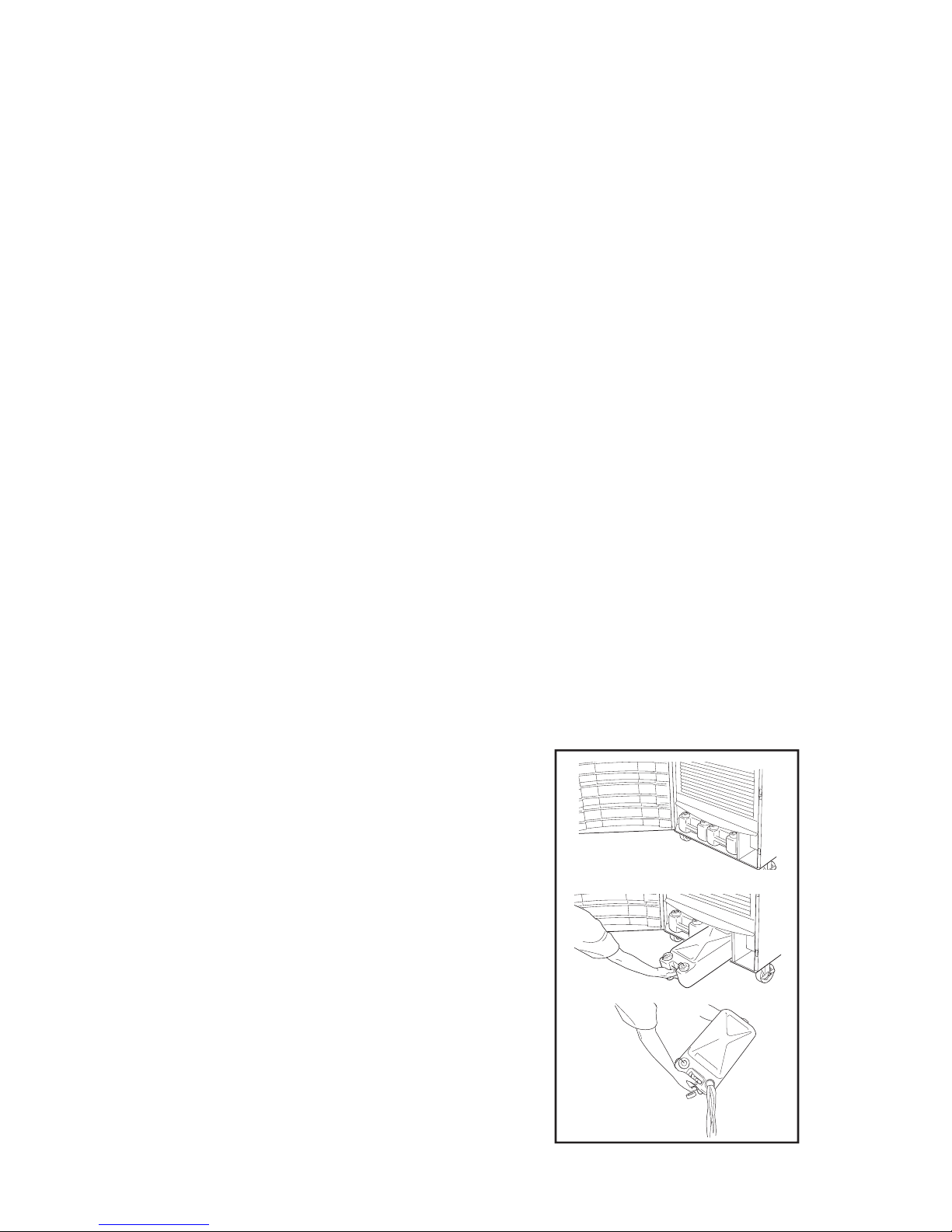
NOTE: If you want to empty the drain tank, while the unit is in operation, press the
gram is running, you must fi rst press the Program
RUN button.
Open the front panel.
Pull the drain tank from the unit.
Remove the cap and empty the drain tank.
Replace the cap and return the drain tank to the
Close the drain tank lid.
If the Program RUN LED is fl ashing, press the
the unit.
Page 11
A drain pump allows continuous operation and eliminates the need for drain tanks.
NOTE:
of level (A) in the pump reservoir, an overfl ow
Drain Switch will stop the compressor operation.
has been set operate from the STOP position,
is discharging water.
To empty the drain tank, refer to instructions, page 14.
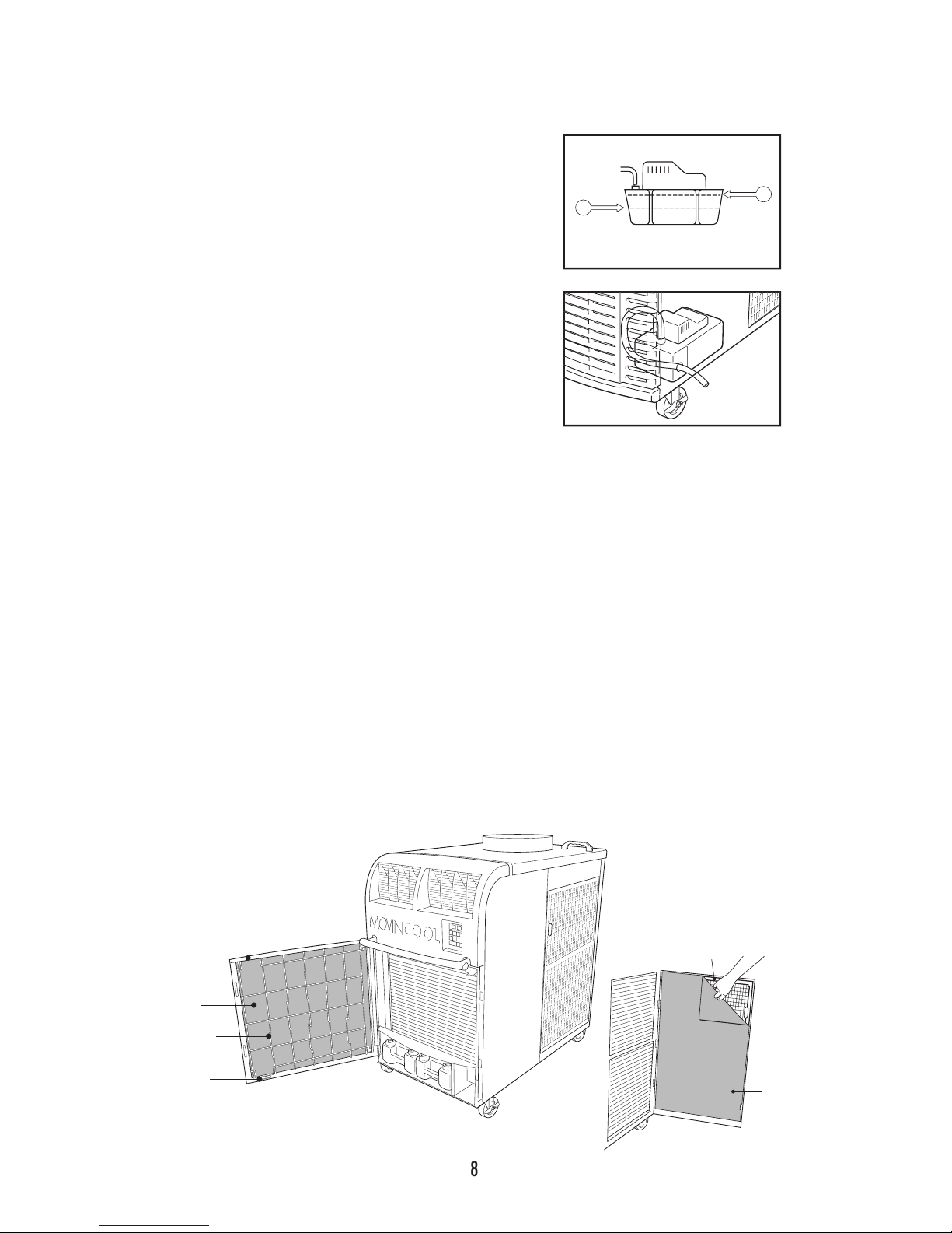
A dirty air fi lter reduces air output resulting in a decrease of the cooling capacity.
Turn the unit off, by pressing the COOL ON/OFF button. If a program is running, you
Remove the 2 air fi lters.
NOTE: To remove the fi lters from the Offi ce Pro 36, open the front panel and side
A
B
CLIP
CLIP
FILTER
WIRE FRAME
VELCRO
®
ATTACHMENTS
FILTER
panel fi lter doors. Unclip the wire frame and remove fi lter.
Page 12
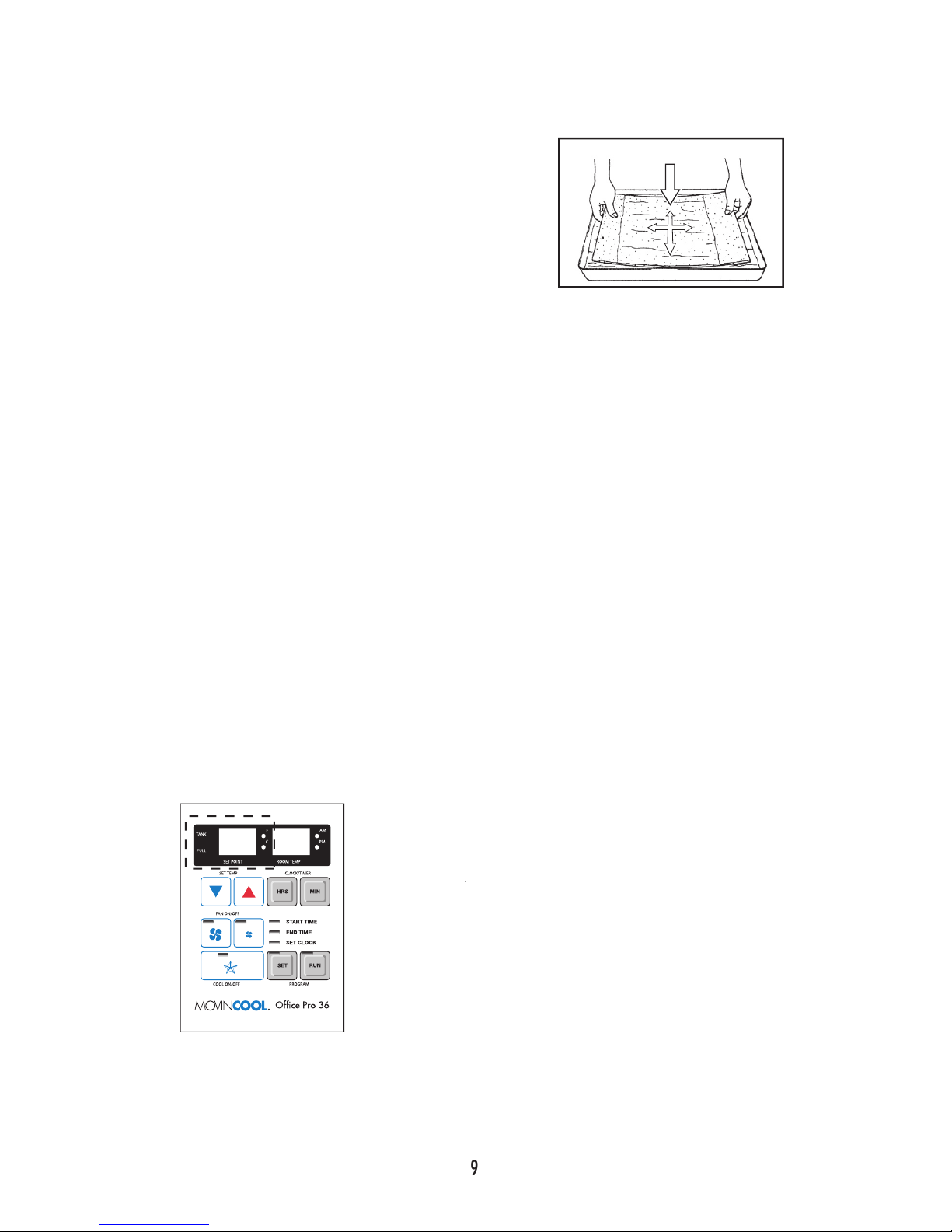
Remove dust from the element with a vacuum cleaner, or rinse in cold or lukewarm
After the element has been cleaned, rinse with
In-Season
Check the prongs and surface of the power cord plug for dust and/or dirt. If dust
Check the power cord, plug and prongs for damage or excess play. If any dam-
Check the air fi lters and drain tank.
Clean the outside of the unit(s) with a damp cloth or mild nonabrasive cleaner.
Off-Season
Operate the unit in Fan Only mode for 8 hours.
Note: Operation is necessary to dry out the inside of the unit.
Disconnect the power cord from the AC outlet.
Check the prongs and surface of the power cord plug for dust and/or dirt. If dust
Check the power cord, plug and prongs for damage or excess play. If any dam-
Clean the air fi lters.
Empty all water from the drain tank.
Self-Diagnostic Codes will be displayed on the Control Board under the following
FILTER
LED fl ashes).
AS When unit disengages the compressor while the
Note: If AS does not disappear from display, contact your distributor.
Page 13
Ground fault breaker tripped Reset breaker
Drain tank is full Empty the drain tank
(
LED will be
fl ashing)
Insuffi cient cooling
Dirty/blocked air fi lters Clean air fi lters
Air inlet/outlet blocked Clear air inlet/outlet
Improper temperature setting Set to desired position
the power cord plug and contact your MovinCool reseller.
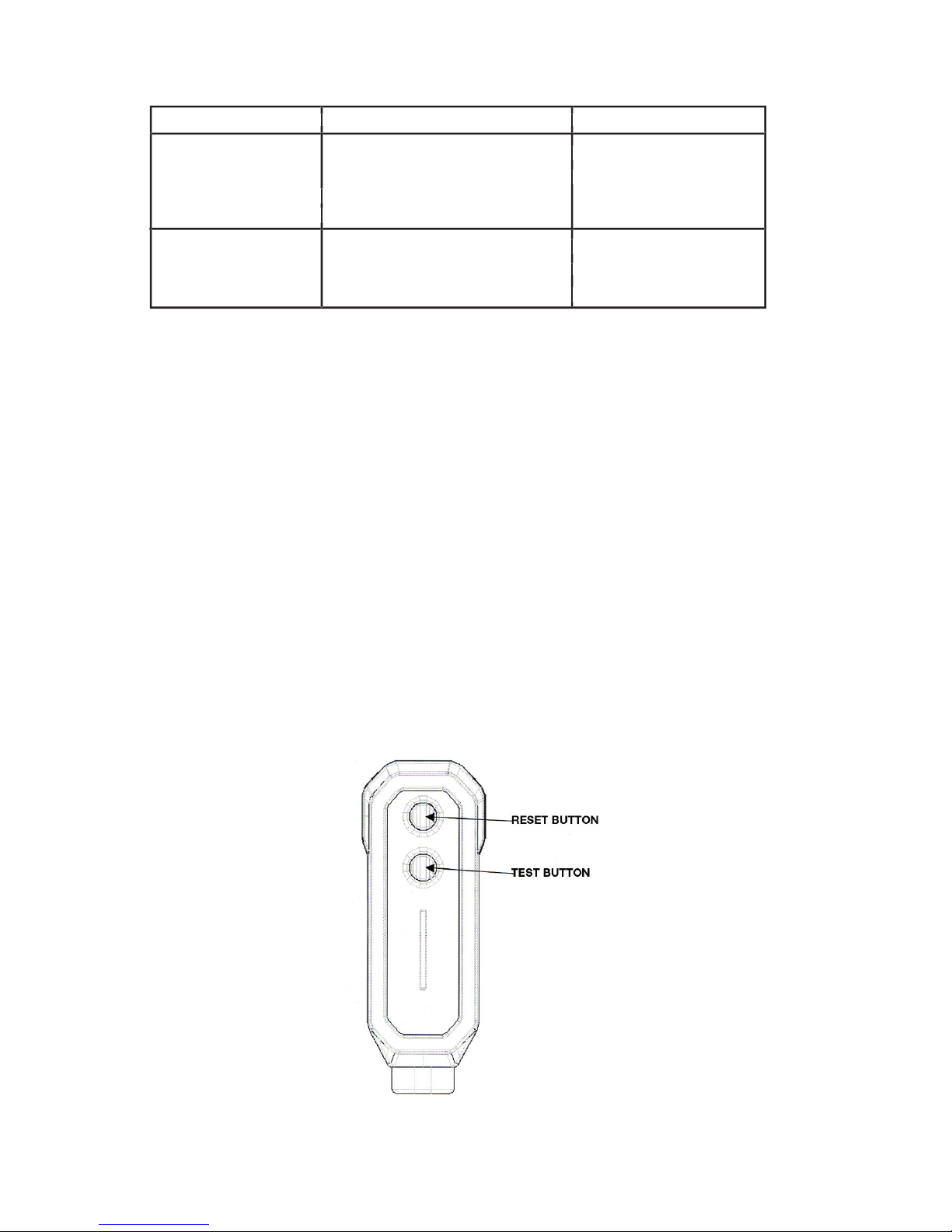
AFCI Power Cord Manual
WARNING: The AFCI device is a non-serviceable part. Attempting to open the
device may expose the user to hazardous electric shock, and voids any warranties
and performance claims. Manufacturer’s liability is limited to the replacement of the
device.
CAUTION:
1. Read manual for proper use and handling of this device.
2. Press “RESET” button before starting the A/C unit. Press “TEST” to check function then “RESET” again. Start the A/C unit.
3. Do not immerse in water
4. This device must only be plugged on appropriate wall outlet.
5. In the event that this device trip, the cause of the malfunction should be corrected fi rst before further use.
6. Using the device beyond recommended voltage poses risk to users.
Page 14

dry bulb 95º F (35º C)
wet bulb 83º F (28.2º C)
humidity 60%
power frequency 60Hz
line voltage single phase 208/230V
power consumption 4.4 Kw
current consumption 19.7 Amps
power factor 99%
starting current 88A
power wiring 10 (3-core) AWG
cooling capability 9,070 Kcal/hr
36,000 BTU/hr
cooling system direct expansion
type of fan centrifugal fan
air volume: evaporator (high speed) 999 ft
/min (1682 m
/h)
evaporator (low speed) 825 ft
/min (1402 m
/h)
condenser (high speed) 1490 ft
/min (2532 m
/h)
evaporator (low speed) 1060 ft
/min (1801 m
/h)
motor output: evaporator (high) 0.21 Kw
condenser (high) 0.33 Kw
type hermetic scroll
output 2.1 Kw
refrigerant type R-22
refrigerant capacity 2.4 lbs (3.1 kg)
compressor overload protector included
fan motor protector included
anti-freezing thermistor included
full drain tank switch included
included
compressor time delay program included
W x D x H (in) 30” x 44” x 52”
W x D x H (mm) 760 x 1117.6 x 1321
weight (lbs/kg) 540/245
inlet air (relative humidity) 95º F (35º C),
60%
65º F (18.3º C),
50%
temperature control included
programmable timer included
two speed fan included
Page 15

This warranty does not cover defects or malfunctions which result from causes
The aforesaid warranty is the only warranty made by DENSO with respect to the
tial, incidental, special or exemplary damages of any kind. DENSO DISCLAIMS
ALL OTHER WARRANTIES WITH REGARD TO THE PRODUCTS, INCLUDING
ALL IMPLIED WARRANTIES OF MERCHANTABILITY AND FITNESS FOR USE.
THERE ARE NO WARRANTIES WHICH EXTEND BEYOND THE DESCRIPTION
______________________________________________________
______________________________________________________
Page 16

First Issue: March 2005
U
L
US LISTED
C
 Loading...