

Page 1
Model: MV-VS1
Installation and User Manual
The MV-VS1 is a mechanical video and audio switching device used to increase the number of inputs to the VCR providing greater
system flexibility and ease of use. Follow the enclosed diagrams to make proper connections.
1111 West Victoria Street
Compton, CA 90220
2061 Cohen Street
Montreal, Quebec H4R 2N7
© 2000 Copyright Magnadyne Corporation
MV-VS1INS Rev.A 5-17-00
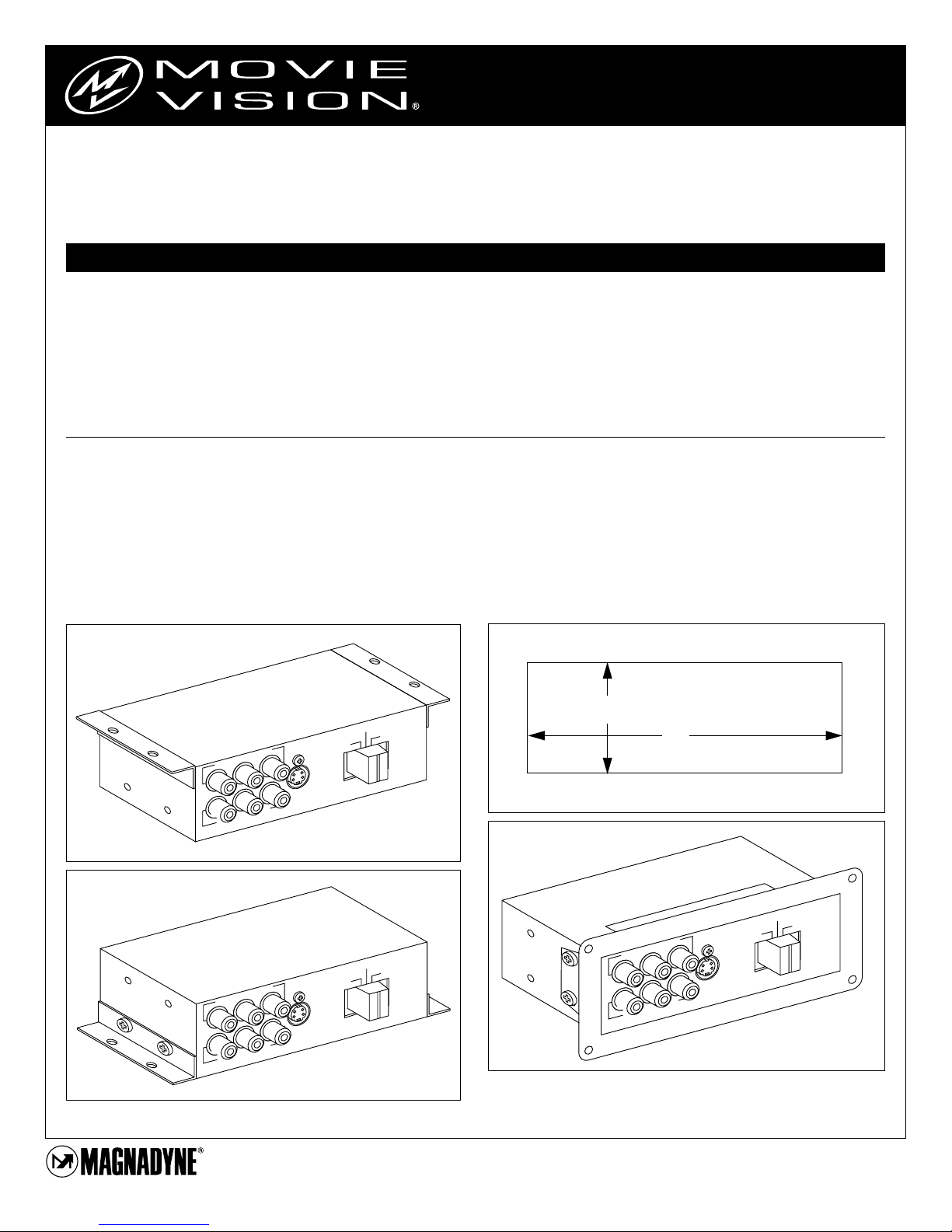
Installation
The MV-VS1 has 3-way mounting capability. It can be mounted
under the dash or under a ledge, on the floor or on top of a ledge
and it can also be panel mounted in a cabinet, console or wall.
Installation Notes:
1. Choose a mounting location that provides easy access by
the end user.
2. Choose a solid mounting surface that will withstand the
pulling and pushing force when the end user is plugging in
and disconnecting devices.
3. If panel mounting, follow the recommendations in point #2.
The mounting surface must be able to withstand the pulling
and pushing force.
Surface Mounting:
Use the “L” brackets provided to secure the MV-VS1 into place.
The brackets can be placed at the top of the MV-VS1 cabinet for
under dash or under ledge mounting or at the bottom of the cabinet for floor or surface mounting. DO NOT mount the MV-VS1
on uneven surfaces which will cause the brackets or chassis to
bend or flex excessively.
Panel Mounting:
Remove the “L” brackets from the MV-VS1 housing and slip on the
panel mount adapter. Use the screws you removed from the “L”
brackets to secure the panel mount adapter to the MV-VS1 chassis.
You must cut a hole in the mounting surface approximately 5” x
1-3/4” in size.
Under Dash Mounting
Surface Mounting
Panel Mounting
Hole Opening
Rear Aux In
t
u
p
In
e
m
a
G
o
e
id
V
Camcorder
Video Game
3
1
/4"
5"
VRL
rd
co
m
a
C
S-Video
Camcorder
t
u
p
r In
e
t
u
p
In
e
m
a
G
o
e
id
V
VRL
rd
o
c
m
a
C
S-Video
Camcorder
t
u
p
r In
e
Camcorder
Rear Aux In
Video Game
t
u
p
In
e
m
a
G
o
e
id
V
VRL
C
t
u
p
r In
e
rd
o
c
m
a
Rear Aux In
Video Game
Camcorder
S-Video
Camcorder
Page 2
Installation and User Manual
Model: MV-VS1
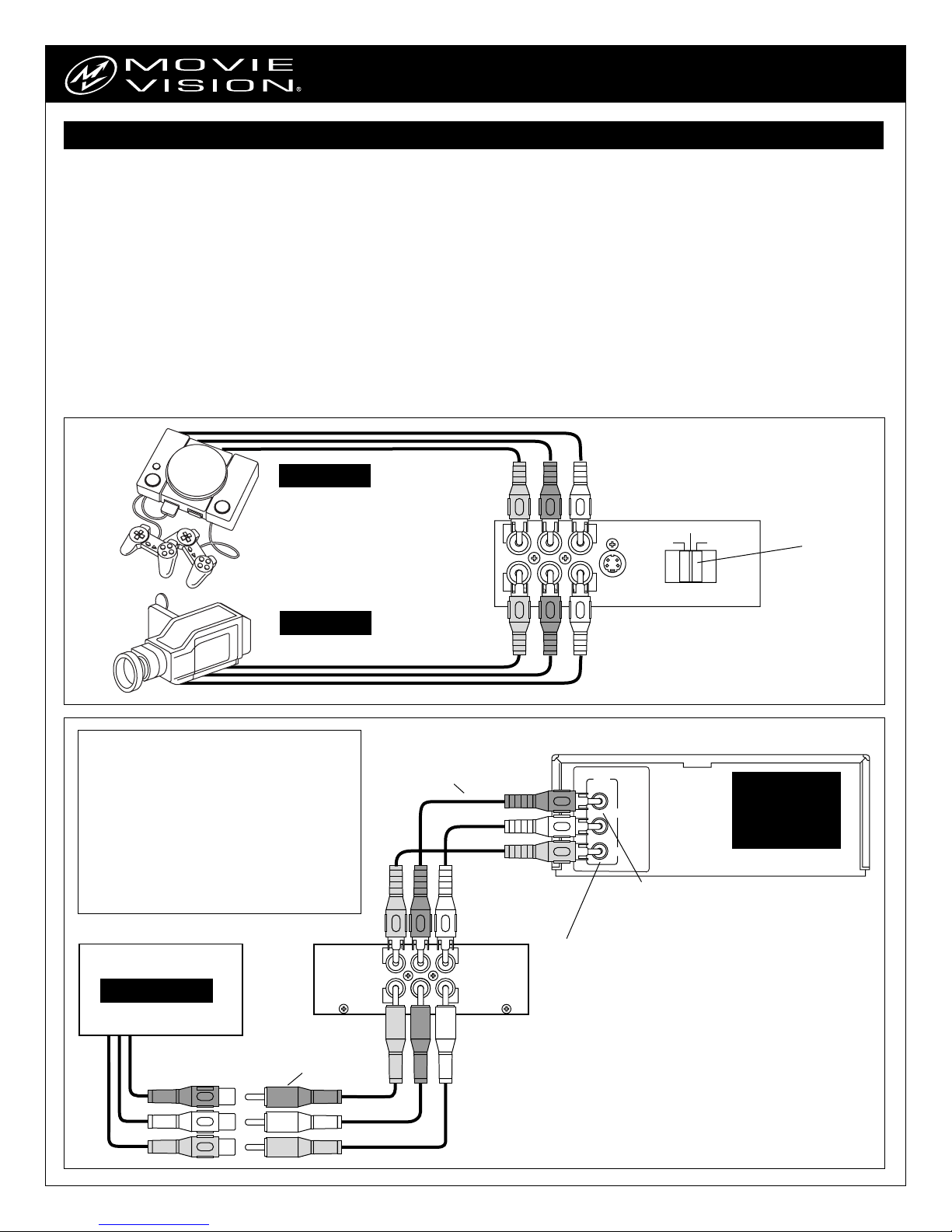
Connection and Operation
1. A 6 foot long RCA male patch cord is provided with the MVVS1 to make the connection from the MV-VS1 output on the
rear panel to the MovieVision Power Supply MV-PM1. Some
installations may require a longer cable which can be purchased at a local electronics store.
2. The “Rear Aux Input” of the MV-VS1 is typically reserved for
permanent items that will not be removed from the vehicle
such as a video game controller, DVD or second VCR.
3. The front panel connections are typically for non-permanent
items that will be removed from the vehicle such as a video
game controller or camcorder. Provided are separate inputs
for a video game controller and a camcorder. There is also a
“S-Input” for those camcorders that have S-Video output.
4. The 3 position switch on the front panel is used to select the
signal source to the MovieVision system.
Note for MovieVision System 1000 : For an auxiliar y source to
be seen on the viewing screen and heard over the headphone or
car radio, the VCR must be turned on and if there is a tape inserted it must be stopped or ejected.
Note for MovieVision System 1002 : The VCR input selection
MUST be set to “Line-In” to allow the audio and video signals
from the MV-VS1 to be seen on the viewing screen and heard
over the headphones or car radio.
Note for Systems other than MovieVision : Consult the users
manual from the VCR for required settings for an auxiliary
source.
Industry Standard Color Code:
Yellow . . . Video Signal
Red = . . . Right Audio Signal
White = . . Left Audio Signal
S-Video . .
A special cable usually supplied
with devices that are S-Video compliant. This
is a video connection only and requires the
use of the Red and White connectors to get
sound reproduction.
All the connectors on the MV-VS1 are female RCA
type with industry standard color code indication.
Any device to be connected to the MV-VS1 will
require a 3 conductor Male-to-Male RCA jumper
cable that will either be supplied with the device or
can be purchased at a local electronics store.
VIDEO GAME
Not Supplied
CAMCORDER
Not Supplied
Video Game Input
VRL
Camcorder Input
S-Video
Camcorder
Camcorder
Rear Aux In
Video Game
Front Panel
Signal
Source
Switch
Supplied
POWER SUPPLY
Not Supplied (MV-PM1)
RCA Male Patch Cord
(MV-VS1)
Supplied
RCA Male Patch Cord
Not Supplied
Rear Aux Input
V
L
Output to VCR
Rear Panel
LINE
OUT
R
AUDIO
L
VIDEO
AUDIO OUT
Connect Red White Male RCA Connectors from
patch cord connected to MV-VS1 Rear Aux Input
connectors
VIDEO OUT
Connect Yellow Male RCA Connector from patch cord
connected to MV-VS1 Rear Aux Input connectors
Permanent Item:
DVD,
Additional VCR,
Video Game
Not Supplied
 Loading...