

Movies 2 go AVXMTGHR1D Operation Manual / Installation Manual
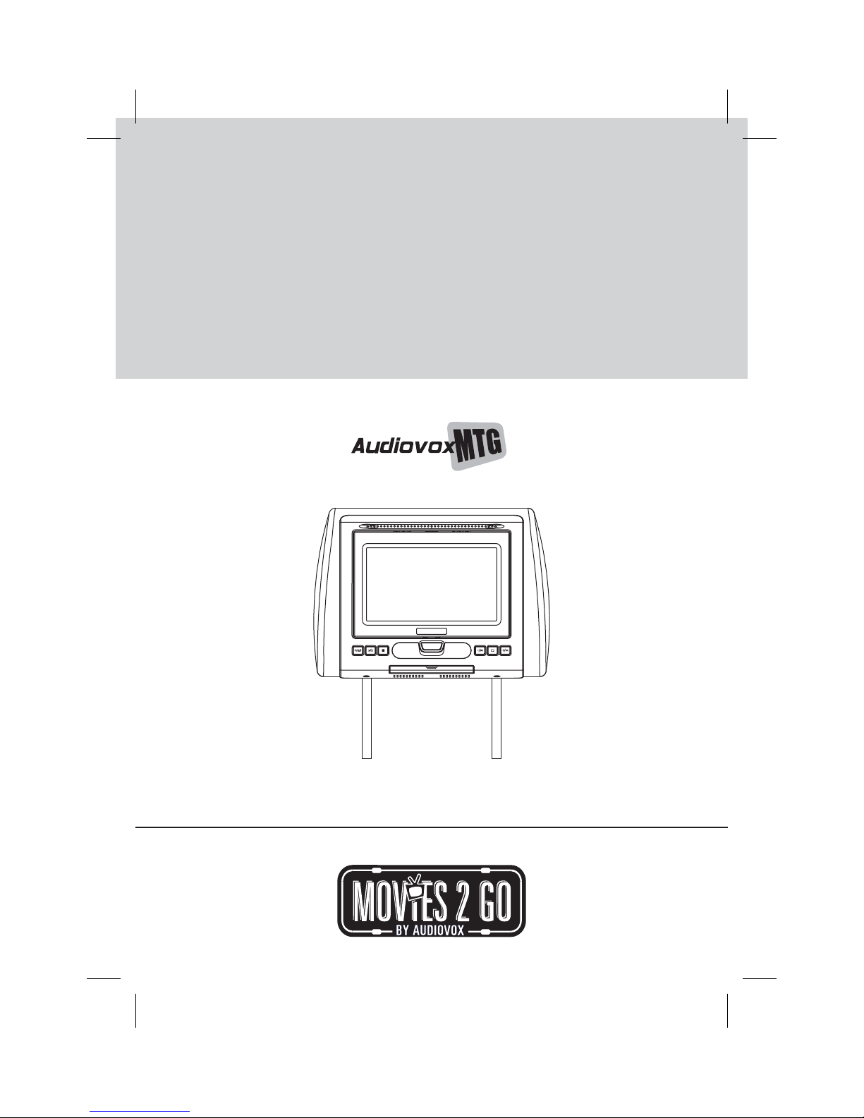
AVXMTGHR1D
7” LCD MONITOR
WITH BUILT-IN DVD PLAYER
FOR REAR SEAT ENTERTAINMENT
PUSH
OPERATION MANUAL / INSTALLATION GUIDE
128-8944B

Important Notice
Installation of headrest products require careful planning and preparation. Be extremely careful
of seats that have airbags built into them. Keep wiring away from any air bag wiring (usually
identified by yellow connectors and yellow wire jackets). Damage to air bag wiring can result in
personal injury to vehicle occupants. If you have any questions regarding wire routing or
installation in avehicle, please contactAudiovoxTechnical Supportat 1-800-225-6074.
When connecting power and ground in a mobile video installation, insure that the ACC wire is
fused at the point where it is connected to the vehicle ACC wiring. Failure to do so can result in
damage to the vehicle if a short circuit develops between the vehicle connection point and the
mobile video product.
An LCDpanel and/or video monitor maybe installed in a motor vehicle and visible to the driver if
the LCD panel or video monitor is used for vehicle information, system control, rear or side
observation or navigation. If the LCD panel or video monitor is used for television reception,
video or DVD play, the LCD panel or video monitor must be installed so that these features will
only function whenthe vehicle is in “park” orwhen the vehicle’s parking brake isapplied.
An LCD panel or video monitor used for television reception, video or DVD play that operates
when the vehicle is in gear or when the parking is not applied must be installed to the rear of the
driver’s seat whereit will not be visible,directlyor
indirectly,to be operator of themotor vehicle.
Licensed under oneor more of the following patents:
Patent NOS. 7,245,274, 6,899,365 and 6,678,892
FEATURES
• 7” Digital Thin Film Transistor (TFT) Active Matrix Liquid Crystal Display (LCD) Monitor
• DVD Player
Built-in
• p m player
Last osition emory for DVD
• Three i
Audio / Video Source nputs (DVD, AV and AUX)
• USB 2.0 port / SD Card Reader input
• Screen mode selection (4:3, 16:9)
• On Screen Display (OSD) for control of picture quality and functions
• Full function remote control
•s ds
Play DVD, CD and MP3 isc
•h
IR eadphone (optional)
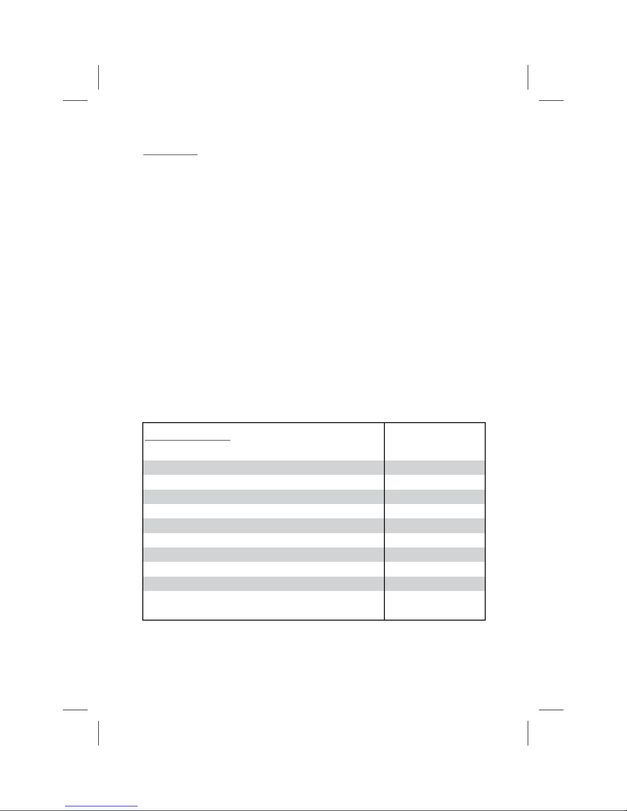
SPECIFICATIONS
Type TFT Active Matrix LCD
Resolution
Pixels
Operation Temperature
Storage Temperature
Backlit life
Video Display System
Headphone Audio Output
Video Output
Power Source
Dimension (L xWxH)
480x234
336,960
32 ~113º F (0 ~ 45º C)
-4 ~ 149º F (-20 ~ 65º C)
20,000 Hours
NTSC / PAL / AUTO
0.03W @ 32 ohms
1.0Vp-p @ 75 ohms
10V~16V DC
147mm x 275mm x 200mm
5.7in x 10.8in x 7.8in
Specifications subject to change without notice.
AVXMTGHR1D 3
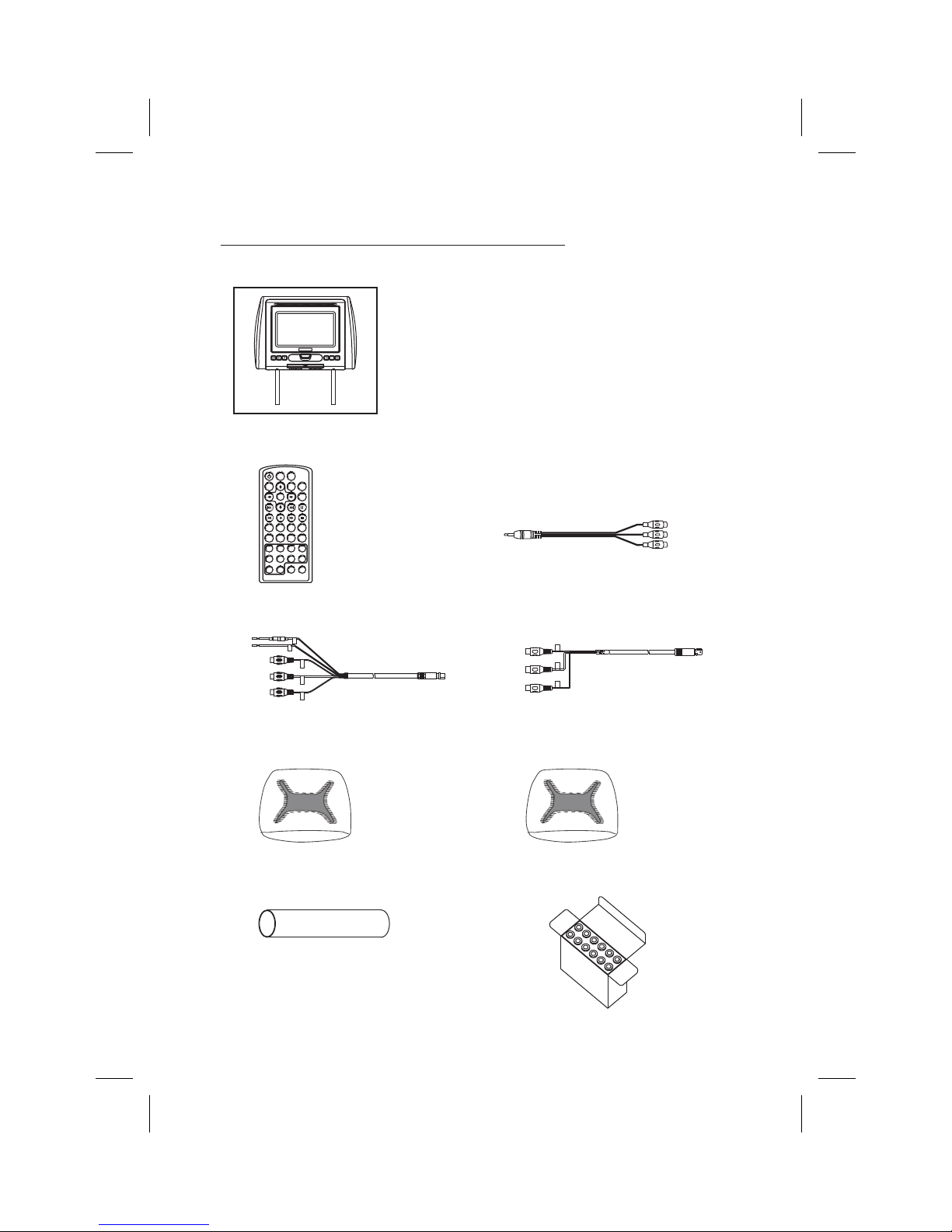
MATERIAL TO USE IN THIS PACKAGE:
1) AVXMTGHR1D System Monitor with DVD Player (AVXMTGHR1D) (1pc)
NOTE: The AVXMTGHR1D monitor hasbeen designed to
be interchangeable from one headrest to the other. The
PUSH
NOTE: Headrest cables are included with the headrest DVD player and the headrest monitor.
POWER SOURCE
DVDSOURCE
VOLUME
MUTE
ENTER
PREV NEXT PAUSE
ZOOM
SYSTEMMENU
1234
5678
90
-
DISCMENU
FMMON/OFF CHANNELSELECT
+
PIX
STOPFFPLAYFR
AUDIOSUBTITLEREPEATSETUP
DISPLAY
1) Remote Control
(P/N 136-5150) - (1pc)
headrests will still have the Green and Red Din cables on
them and should be connected to their respective
connectors. The headrest cover from the manufacturer is
covered with shalecolored vinyl.
2) AV Adapter Cable
(P/N )-(1pc)112B3227
3) AV IN / Power Cable, 8 Pin Din to 3 RCA (Red)
(P/N 112-4149)-(1pc)
5) Black Vinyl Headrest Cover
(P/N 126-1377)-(1pc)
7)
Shrink Tubing, Black
(P/N 138-1495 )-(2pcs)
4) AV OUT Cable, 8 Pin Din to 3 RCA (Green)
(P/N 112-4160)-(1pc)
6) Pewter Vinyl Headrest Cover
(P/N 126-1378)-(1pc)
8)
Support Tube Adaptor Box
(P/N )-(1box)
170-0161
AVXMTGHR1D4
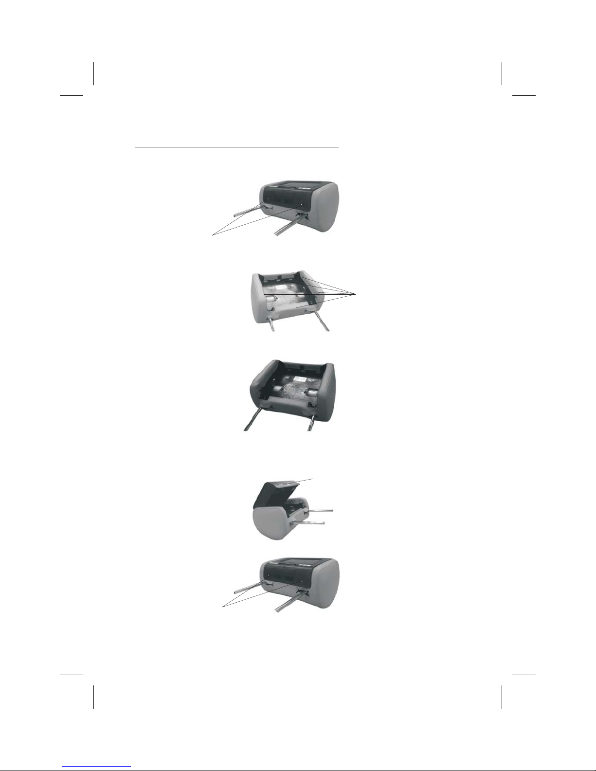
HEADREST COVER REPLACEMENT:
NOTE: If desired, replace the headrest cover before installing the headrest in the vehicle.
1. Using a Philips screwdriver, unscrew the two Philips screws and lift the bottom edge
of the monitor upward.
Unscrew Philips Screws
2. Remove the .velcro tabs securing the headrest cover
Remove Velcro Tabs
3. Replace the headrest cover with the desired color and secure the headrest cover by
re-attaching the velcro tabs.
4.Place the monitor cable into the space on the right side of the headrest and lower the
monitor into position to align the two Philips screws with the screw holes in the headrest.
Close the screen and press the PUSH button to secure the screen.
Push
5.Tighten screws
Tighten Philips Screws
AVXMTGHR1D 5

VEHICLE PREPARATION
1) Decide on the system configuration and the options that will be installed.
2) Read the manuals and get familiar with the electrical requirements and
connections.
3) Decide on the mounting locations and methods of mounting the products that
will be connected to the AVXMTGHR1D.
4) Prepare the vehicle by removing any interior trim necessary to gain access to
the vehicle's wiring as well as all areas where interconnecting wire harnesses
will be located. The mounting method, and the location will vary from vehicle to
vehicle, so this manual will only focus for the installation of the AVXMTGHR1D
Monitors in the supplied configuration. The best location for the AVXMTGHR1D
System components is:
a. Monitors: Vehicle specific Headrest The Master Monitor should be
installed in the passenger position most used.)
5) Locate an accessory power source (+12VDC present when the ignition key is in
the accessory and run positions. 0VDC should be present when the ignition key
is in the OFF position), a constant power source (+12vdc) at all times,
regardless of the ignition key and a good ground. Generally, these wires can be
found at the ignition switch or fusebox.
Ensure that both the constant and accessory power is fused at the
NOTE:
source. Failure to do so may result in vehicle wiring damage.)
6) Run the wiring harnesses throughout the vehicle as necessary. (Refer to the
Wiring Diagrams on page 8, as well as the wiring instructions for the individual
components and accessory options being installed). Be sure, that all the wiring
is protected from sharp edges and is routed in such a manner that it will not be
pinched, when it is fully installed. Be sure to leave enough slack in the wiring at
each component to allow sufficient working room. Be sure to leave enough slack
in the monitor cables to allow the headrest to move up or down, and seat
movement.
NOTE:
7) Remove all the A/V system components from their packaging and then place
them in the vehicle at their respective locations.
AVXMTGHR1D6

8) Install the headrests:
a. Remove vehicle's original headrests.
b. insert appropriate support tube adaptors in vehicle post guides. (if needed)
c. Hold the headrest above the seat and insert the two cables into the vehicle
support guides Make sure that the headrest is in the correct position (Display
facing the rear).
d. Route the cables through the seat back and out the bottom of the seat while
pulling the cables to remove the slack. Be sure to leave enough slack in the
monitor cables to allow the headrest to move up or down.
9) Connect all the components together (electrically) and verify proper operation of
all the system functions.
Wireless FM Modulator
The AVXMTGHR1D is equipped with a built-in wireless FM Modulator, that
allows you to listen to the DVD audio signal by tuning your vehicle’s radio to the
selected frequency, ( 87.7MHz, ( 88.1MHz, 88.5MHz,
88.9MHz, 106.7.1MHz, 107.1MHz, 107.5MHz, 107.9MHz.
This feature is accessed by using the FM transmitter buttons on the remote
(FMM ON/OFF, and CHANNEL SELECT).
Whenever the FM Modulator is on, broadcast reception on the vehicles radio will
be poor. Switching off will allow normal radio reception.
NOTE:
large cities, urban areas), the reception of the FM signal may not be satisfactory,
resulting in static, distorted sound or signal bleed thru from strong local radio
stations. This is not a defect in the product, but the result of a stronger local radio
station overpowering the wireless FM transmitter in your headrest monitor.
CH5 CH6 CH7 CH8
In certain areas where there are a large number of FM radio stations (e.g.
CH1
the FM Modulator
CH2 CH3 CH4
AVXMTGHR1D 7
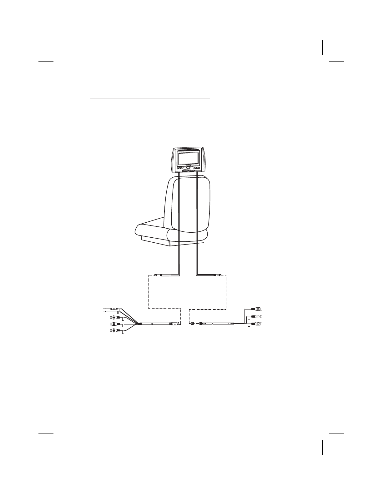
AVXMTGHR1D WIRING DIAGRAM
Headrest Monitor
SH
PU
12V+VDC
Ground-
Video In Yellow
Audio In Right Red
Audio In Left White
8 Pin (M) Din Cable Red with RCA Cable
(P/N 112-4149)-(1pc)
RED
GREEN
Video Out Yellow
Audio Out Right Red
Audio Out Left White
8 Pin (M) Din Cable Green with RCA Cable
(P/N 112-4160)-(1pc)
AVXMTGHR1D8
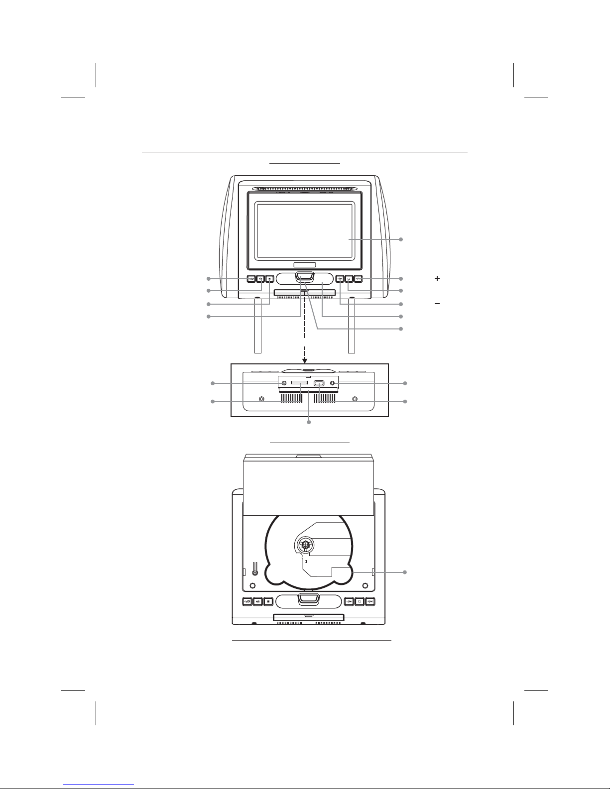
AVXMTGHR1D
CONTROLS AND INDICATORS DIAGRAM
(FRONT VIEW)
LCD PANEL
POWER/SOURCE
PLAY/PAUSE
STOP
SCREEN RELEASE
AUX IN JACK
SD CARD READER
PUSH
PULL DOWN
AUXIN
SD USB
PHONE
COVER
(BOTTOM VIEW)
VOLUME /NEXT
SYSTEM MENU
VOLUME PREVIOUS/
IR SENSOR
IR HEADPHONE
TRANSMITTER LENS
HEADPHONE JACK
USB PORT
AVXMTGHR1D 9
DVD DISC
PUSH
(FRONT VIEW MONITOR OPEN)
 Loading...