

Movi M10 Installation Instructions Manual
MōVI M10 Top Mount Upgrade
INSTALLATION INSTRUCTIONS
Thank you for your purchase of the new Top Mount Upgrade Kit for the MōVI M10. This
modication allows the M10 to operate without constraints in the SkyView top mounted
position on your ALTA, TERO, or any stable vertical mount like a tripod.
Please give yourself about an hour and a clear work space to work in. We recommend you
install our Toad in the Hole kit while performing this upgrade which will allow you to get
the most out of your Top Mount Upgrade.
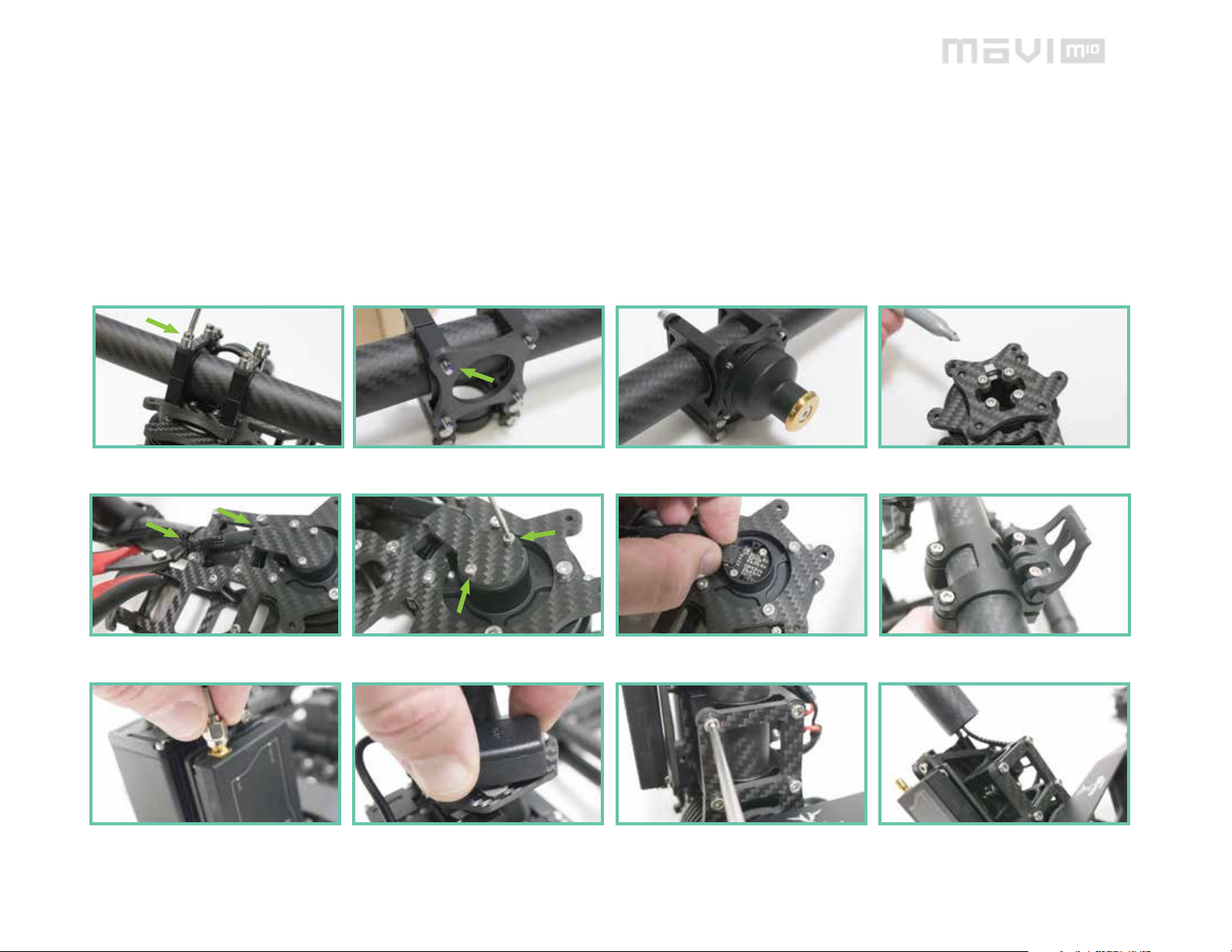
PART 1 : DISASSEMBLY AND PREPPING THE UNIT.
01. Loosen the 4 bolts holding the handle bar on to the
pan assembly of your MoVI M10.
(optional) Loctite screws and Install Toad in the Hole Male. 02. Mark motor to show front of unit with marker.
Tools needed:
Wire cutter / diagonal side cutter.
1.5mm hex wrench, straight or ball tip.
2.0mm hex wrench, straight tip (not ball end.)
2.5mm hex wrench, straight or ball tip.
Needle nose plier, or similar (optional.)
Adhesive remover (optional.)
Toad in the Hole Kit (optional.)
03. Lay unit on it’s side, cut and remove zip ties from
pan motor assembly.
07. Unscrew the GPS SMA connector. 08. Twist the GPS module o of the carbon plate and
04. Remove these screws, the carbon plate, and metal
plate underneath.
clean any tape from GPS, set aside.
05. Unplug the motor, careful not to pull from the wire
but the connector.
09. Loosen the 4 screws holding the vertical tube approx
2-5 turns until the tube is just loose enough to turn.
06. Loosen pan adjustment levers, or unscrew pan clamp
and remove pan assembly from unit and set aside.
10. Remove the tube and set it aside.
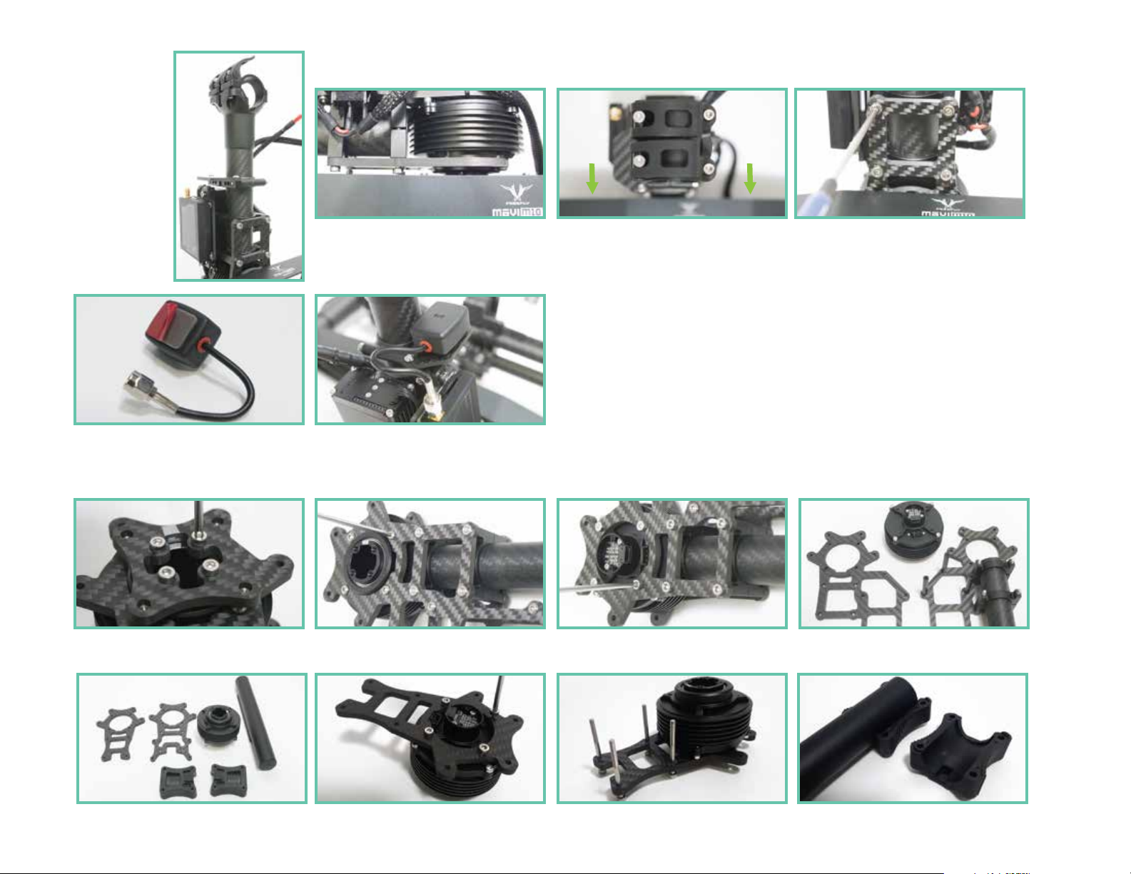
PART 2 : CONVERTING THE LOWER GIMBAL.
11. Install your new keyed pan assembly as shown,
the levers should be pointing to the left of the unit.
12. Slide the tube in until it is just ush with the bottom
clamps and is not touching the motor.
15. Apply provided tape to your GPS unit and peel o
red backing.
16. Install your GPS back onto the plate as shown and
screw back on the SMA connector.
PART 3 : CONVERTING THE PAN ASSEMBLY.
16. Remove the 4 bolts from the motor and set the
carbon plate and bolts aside.
17. Remove the 4 button head bolts with a 2mm driver;
use caution and make sure the driver is fully seated to
avoid stripping.
13. From above, look down at the gimbal and twist the
keyed quick release until it is as square as possible with
the roll beam. (this can be adjusted later.)
18. Remove the 8 bolts with a 2.5mm driver, and the 5
button head bolts with a 2mm driver. Use pliers to hold
the posts if they spin.
14. Tighten the 4 screws evenly in a cross pattern until
they are tight.
19. Pull the carbon plates apart, save the motor and set
aside or discard the rest.
20. Unpack the parts shown.
21. Using the carbon plate without threaded inserts,
install it to the motor as shown so the plug ts in the cut
out of the carbon and attach with your original socket
head bolts.
21. Insert the 4 M3X37 screws provided through the
carbon plate with motor as shown, and lay at on your
work surface.
22. Place your metal tube with the open end inside the
plastic clamp as shown, place the matching part over
the top of the tube.
 Loading...