

Page 1
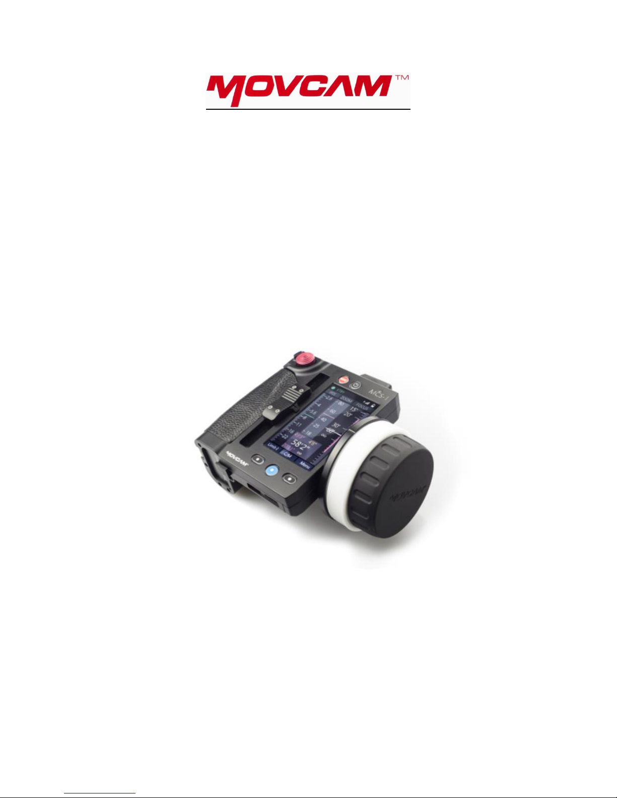
501-101 3 AXIS LENS CONTROL SYSTEM
QUICK GUIDE
JANUARY 2017
WWW.16X9INC.COM
Page 2

Supplied system contents:
- MCS-1 main unit with hand strap and shoulder strap
- MHW-1 hand wheel unit with scale
- MRS-1 motor control driver with 19mm rod clamp bracket, 19:15mm spacer
- 3X UM3 motor with 0.8 pitch drive gear, 19mm rod clamp bracket, 19:15mm spacer
- PWD-1 D-tap 12 volt DC power cable for the MRS-1
- CRL-1 direct wire control cable
- Hard Case
Optional required accessory:
- NPF-550/570 battery and charger
The 3 AXIS motor control system is designed to work with camera lenses featuring external gear interfaces.
The system is designed to operate from supplied DC power of 12-24V. Operational wireless range of 600 feet
dependent on line of sight. ISM2.4M frequency with 9 selectable channels.
Getting started:
- Mount the motors to the camera lens via rods mounted to the camera. Place the lens travel anywhere in
the middle and engage the motor to the lens.
- Mount the MRS-1 to the camera. Plug in PWD power cable to the MRS (red collar connector)
- Connect the motors to the MRS-1 via the control cables mounted on the UM3 (green collar connector).
Connect the appropriate motors to the connectors on the MRS according to the function (focus to MOT-F
input, zoom to the MOT-Z input, iris to the MOT-I input)
- Power on the MRS and the MCS. Make sure the wireless channels match between the units. Change as
needed.
- -MRS is connected to the MCS when signal bars icon is visible on the MCS screen next to the channel
number indicator.
- Calibrate the motors.
Auto calibration is available by pressing and holding the blue function button located at the
bottom of the MCS display.
Calibration of individual motors can be accessed at the UM3 motor by pressing the RED button
located by the cable for 3 seconds.
- Once motor calibration is completed the system should now control all motors.
- If during calibration the motor does not turn the lens for proper rotation, check the motor torque setting
found in the MCS menu screen. Low torque settings will not supply enough power to the motor for some
Cinema lenses for proper calibration.
Page 3

MCS Hand Set Features:
- Located on the MCS handset behind the zoom knob is a red multifunction button. This button is
designed for two functions.
o Pressing and holding down this button will access the zoom speed as well as ZAP function on the
display. Once in this screen quick press the button to return to the main screen.
o Range limit of the motor travel can be programed with a quick press of this button.
Select the function to be limited (Focus, Iris, or zoom).
Located on the MCS screen on the lower left is “LIMIT”. Touch to access the
selection screen and select the function desired.
Go to your start point and quick press. A line should now appear next to the distance
marking.
Go to your end point and quick press. A solid line should now appear next to the scale
from your start point to end point programed. Now the motor is limited to travel within
this range.
To clear limit settings, quick press and the solid line should now disappear.
- Marker points can be programed into the focus scale.
o Quick press the blue center button located on the lower bottom of the screen.
o The lower screen should now display ( “MARKER”, “Remove”, “Back” )
o Go to your first mark point and press marker. A colored arrow should now appear next to the
distance point.
o Repeat step above to add each additional point.
A maximum of 10 marker points can be assigned with each displaying a different color.
o To remove the markers, go to each marker point and press remove.
- The MCS is able to accept lens mapping. If no mapping is done, scale display can be changed to represent
percentage. To enable percentage follow the steps:
o Press “Menu”
o Press “Camera & Lens”
o Press the dot next to “Percentage”
o If percentage is selected the dot will be blue. Press again to disable.
- The MCS hand wheel features adjustable dampening. To adjust follow the steps:
o Remove the focus scale and locate the hole just above the detent/key pin on the hand wheel.
Located inside the hole is a 2.5mm hex head screw.
o Using a 2.5mm hex wrench, rotate the screw.
Clockwise will increase tension.
Counter clockwise will decrease tension.
o Once adjusted, replace the scale.
 Loading...