

Mouvex SLS4 i, SLS8 i Original Instructions Manual
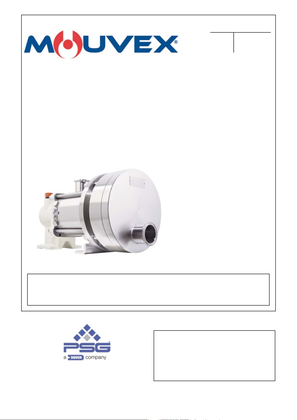
SLS4 i - SLS8 i
PUMPS
INSTALLATION
OPERATION
MAINTENANCE
INSTRUCTIONS 1004-E00 e
Section 1004
Effective February 2018
Replaces December 2016
Original instructions
Your distributor :
Z.I. La Plaine des Isles - F 89000 AUXERRE - FRANCE
Tel. : +33 (0)3.86.49.86.30 - Fax : +33 (0)3.86.49.87.17
contact@mouvex.com - www.mouvex.com
WARRANTY :
SL Series pumps are covered 24 months by warranty within the limits mentioned in our General Sales Conditions.
In case of a use other than that mentioned in the Instructions manual, and without preliminary agreement of MOUVEX,
warranty will be canceled.
2/31
NT 1004-E00 02 18 SLS4 i - SLS8 i e
ECCENTRIC PISTON PUMP
MOUVEX PRINCIPLE
SAFETY INSTRUCTIONS, STORAGE, INSTALLATION AND MAINTENANCE
SLS4 i - SLS8 i MODELS
TECHNICAL CHARACTERISTICS
- Maximum pump speed : 750 rpm
- Running temperatures :
• ambient ......................................................-15°C → .+ 40°C
• continuous pomped product.......................-15°C → .+100°C
• washing / rinsing / sterilisation product...... 0°C → .+121°C
• heating fluid (jacket)...................................-15°C → .+180°C
- Maximum suction pressure :
• In normal use, the suction pressure must be higher than the
required NPSH and less than 1,5 barg (21,75 psig).
• During CIP/SIP of the pump, the suction pressure must not
exceed 3 barg (43,5 psig).
• Pump stopped, the pressure must not exceed 6 barg
(87 psig).
- Acceptable maximal differential pressure :
• SLS4 i ..........................10 bar (145 psi)
• SLS8 i .......................... 6 bar (87 psi)
- Maximum pressure jacket : 5 barg (72,50 psig)
- Cylinder capacity :
• SLS4 i ..........................0,108 litre
• SLS8 i ..........................0,178 litre
1. CODIFICATION . . . . . . . . . . . . . . . . . . . . . . . . . . . . . . . . .3
2. OVERALL DIMENSIONS . . . . . . . . . . . . . . . . . . . . . . . . . .4
3. INSTALLATION . . . . . . . . . . . . . . . . . . . . . . . . . . . . . . . . .9
3.1 Installation design . . . . . . . . . . . . . . . . . . . . . . . . . . . . .9
3.2 Orientation of the pump ports . . . . . . . . . . . . . . . . . . .10
3.3 Direction of rotation . . . . . . . . . . . . . . . . . . . . . . . . . . .10
3.4 Protection of the pump installation . . . . . . . . . . . . . . .11
3.5 Hoisting devices . . . . . . . . . . . . . . . . . . . . . . . . . . . . .11
3.6 Unit Assembly . . . . . . . . . . . . . . . . . . . . . . . . . . . . . . .11
4. UTILISATION . . . . . . . . . . . . . . . . . . . . . . . . . . . . . . . . .14
4.1 Noise level . . . . . . . . . . . . . . . . . . . . . . . . . . . . . . . . .14
4.2 Commissioning . . . . . . . . . . . . . . . . . . . . . . . . . . . . . .14
4.3 Dry running . . . . . . . . . . . . . . . . . . . . . . . . . . . . . . . . .14
4.4 Pump stop . . . . . . . . . . . . . . . . . . . . . . . . . . . . . . . . . .14
4.5 Scrapping . . . . . . . . . . . . . . . . . . . . . . . . . . . . . . . . . .14
5. CLEAN IN PLACE (CIP) & STERILISATION IN PLACE
(SIP) . . . . . . . . . . . . . . . . . . . . . . . . . . . . . . . . . . . . . . . .15
5.1 General . . . . . . . . . . . . . . . . . . . . . . . . . . . . . . . . . . . .15
5.2 CIP circuit recommended . . . . . . . . . . . . . . . . . . . . . .15
5.3 Pumps arranged in series . . . . . . . . . . . . . . . . . . . . . .15
5.4 Pumps arranged in parallel . . . . . . . . . . . . . . . . . . . . .16
5.5 Successive cycles . . . . . . . . . . . . . . . . . . . . . . . . . . . .17
5.6 Sterilisation In Place (SIP) . . . . . . . . . . . . . . . . . . . . .17
6. MAINTENANCE . . . . . . . . . . . . . . . . . . . . . . . . . . . . . . . .17
6.1 Necessary tools . . . . . . . . . . . . . . . . . . . . . . . . . . . . .17
7. OPENING OF THE PUMP . . . . . . . . . . . . . . . . . . . . . . . .18
7.1 Assembly / Dismantling . . . . . . . . . . . . . . . . . . . . . . . .18
7.2 Checking of parts . . . . . . . . . . . . . . . . . . . . . . . . . . . .19
8. ASSEMBLY OF CYLINDER/PISTON . . . . . . . . . . . . . . . .20
9. PROTECTION OF THE BELLOWS . . . . . . . . . . . . . . . . . .22
10. DISMANTLING OF THE BELLOWS . . . . . . . . . . . . . . . .23
11. CHANGING THE ORIENTATION OF THE PORTS . . . . .26
11.1 Discharge port . . . . . . . . . . . . . . . . . . . . . . . . . . . . . .26
11.2 Suction port . . . . . . . . . . . . . . . . . . . . . . . . . . . . . . . .26
12. DRAINING OF BEARING . . . . . . . . . . . . . . . . . . . . . . . .27
13. STORAGE . . . . . . . . . . . . . . . . . . . . . . . . . . . . . . . . . . .28
13.1 Short duration (≤ 1 month) . . . . . . . . . . . . . . . . . . . .28
13.2 Long duration (> 1 month) . . . . . . . . . . . . . . . . . . . .28
13.3 Restarting . . . . . . . . . . . . . . . . . . . . . . . . . . . . . . . . .28
14. TROUBLESHOOTING . . . . . . . . . . . . . . . . . . . . . . . . . .29
15. CERTIFICATE OF CONFORMITY . . . . . . . . . . . . . . . . .31
TABLE OF CONTENTS Page
USED PRESSURE UNITS
Unit without suffix :
Differential pressure, for example, pressure difference between
equipment suction and discharge.
Unit with suffix
"a" :
Absolute pressure.
Unit with suffix
"g" :
Gauge pressure, given regarding to atmospheric pressure
(~101325 Pa, taken at 1 bar / 14,5 psi in this IOM).
P
P
f
Psuc
Pdis
Pump
Example :
Psuc = -0,2 barg = 0,8 bara
Pdis = 8,8 barg = 9,8 bara
∆P = Pdis - Psuc = 9 bar
Definition of safety symbols
This is a SAFETY ALERT SYMBOL.
When you see this symbol on the product, or in the manual,
look for one of the following signal words and be alert to the
potential for personal injury, death or major property damage.
Warns of hazards that WILL cause serious personal injury,
death or major property damage.
Warns of hazards that CAN cause serious personal injury,
death or major property damage.
Warns of hazards that CAN cause personal injury or property
damage.
NOTICE
Indicates special instructions which are very important and
must be followed.
DANGER
WARNING
CAUTION
asp
Pompe
re
3/31
NT 1004-E00 02 18 SLS4 i - SLS8 i e
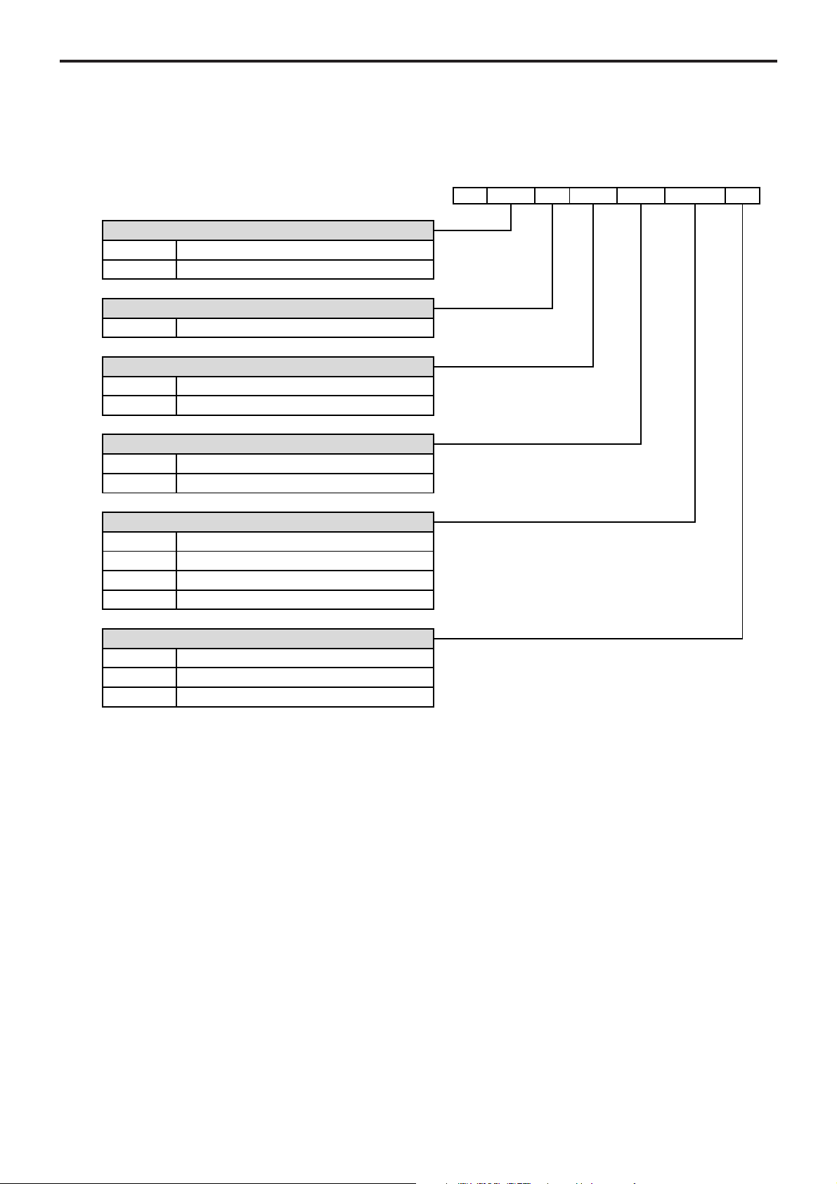
1. CODIFICATION
Flowrate
4- 4 m3/h
8- 8 m3/h
Temperature
I Standard
Conception
ST- Standard
EV- Heating jacket
Seals
VT- FKM
CVT- FKM encapsulated FEP
Connections-Flanges
AF50- Flanges DIN11864-BF-A D50
CLAS51- Connections CLAMP ASME BPE-2009 D51
SMS51- Connections SMS1145 D51
DIN50- Connections DIN11851 D50
SLS
4- I ST- VT- AF50- -
Transmission security
- Without
BMS- Bellows Monitoring System
BMSA- ATEX Bellows Monitoring System
4/31
NT 1004-E00 02 18 SLS4 i - SLS8 i e
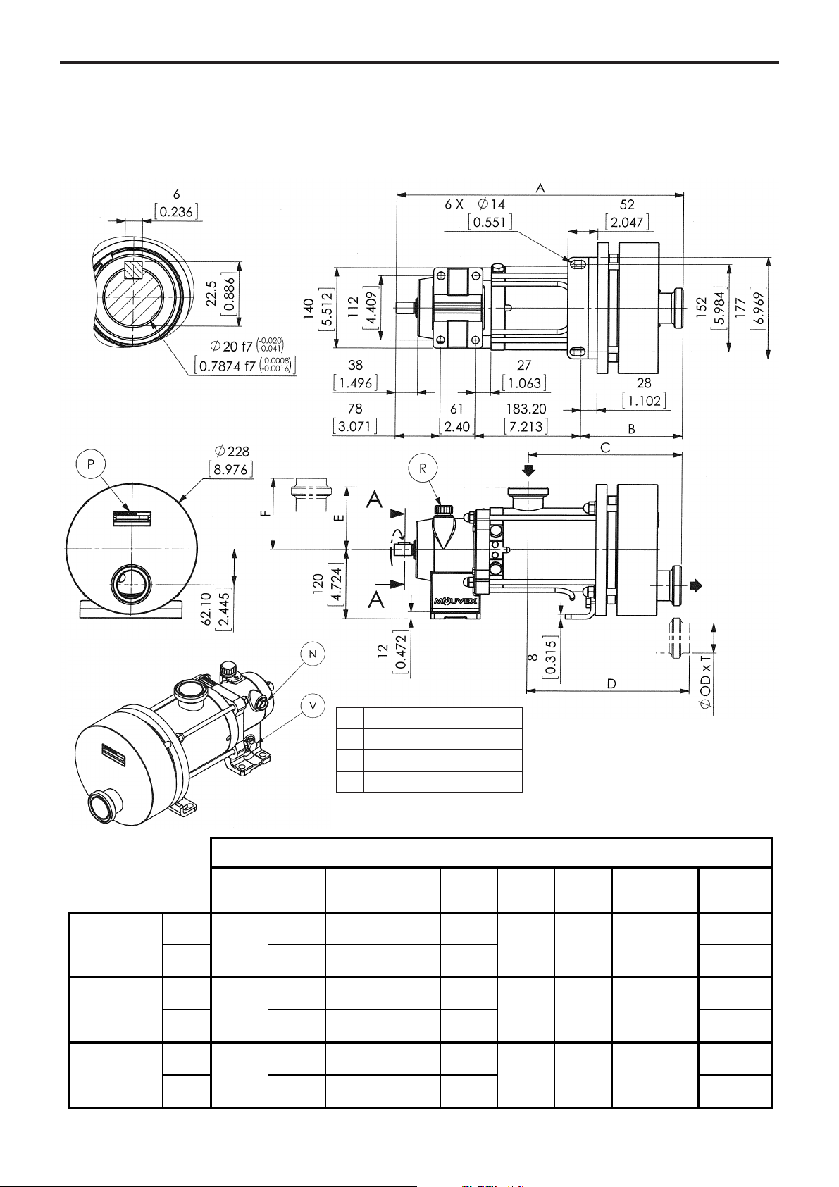
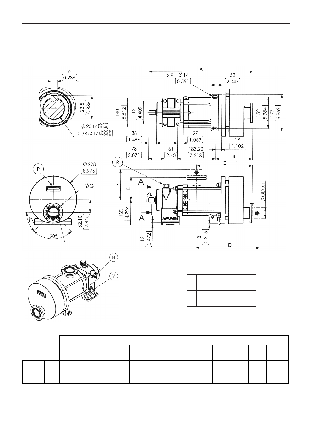
2. OVERALL DIMENSIONS
Pump plate
Filling / Breather
Draining
Oil level
P
R
V
N
SLS4 i - SLS8 i
with connections
Connections
Weight
kg [lb]
CAUTION : When welding the connections, the bellows should be protected.
SECTION A-A
SMS 1145
Clamp
ASME BPE
2009
DIN 11851
SLS4
SLS8
SLS4
SLS8
SLS4
SLS8
DN A B C D E F
499 177 267 287 49
51 [19.646][6.969][10.512][11.299] 109 129 51 x
[2.008] 516 194 284 304 [4.291][5.079][2.008 x
[20.315] [7.638][11.181][11.969][113]
499 177 267 287 49
51 [19.646][6.969][10.512][11.299
[2.008] 516 194 284 304 [4.291][5.079][2.047x
[20.315] [7.638][11.181][11.969][113]
499 177 267 287 49
50 [19.646][6.969][10.512][11.299] 109 129 55 x
[1.969] 516 194 284 304 [4.291][5.079
[20.315] [7.638][11.181][11.969][113]
] 109 129 52 x
OD x T
][2.165 x
1,25
0.049]
2
0.079]
2,5
0.098]
[109]
51
[109]
51
[109]
51
5/31
NT 1004-E00 02 18 SLS4 i - SLS8 i e
2. OVERALL DIMENSIONS (continued)
Pump plate
Filling / Breather
Draining
Oil level
P
R
V
N
SLS4 i - SLS8 i
with flanges
Flanges
Weight
kg [lb]
CAUTION : When welding the connections, the bellows should be protected.
SECTION A-A
4 x Ø L on Ø K
DIN11864
BFͲA
DN A B C D E F ØG ØL ØK
SLS4
SLS8
50 [19.646][6.969][10.512][11.299] 109 129 53 x
[1.969] 516 194 284 304 [4.291][5.079][2.087x
499 177 267 287 49,5
[20.315] [7.638][11.181][11.969][114]
xT
OD
1,5
0.059]
94 9 77 [110]
[3.701][0.354][3.031] 51,5
6/31
NT 1004-E00 02 18 SLS4 i - SLS8 i e
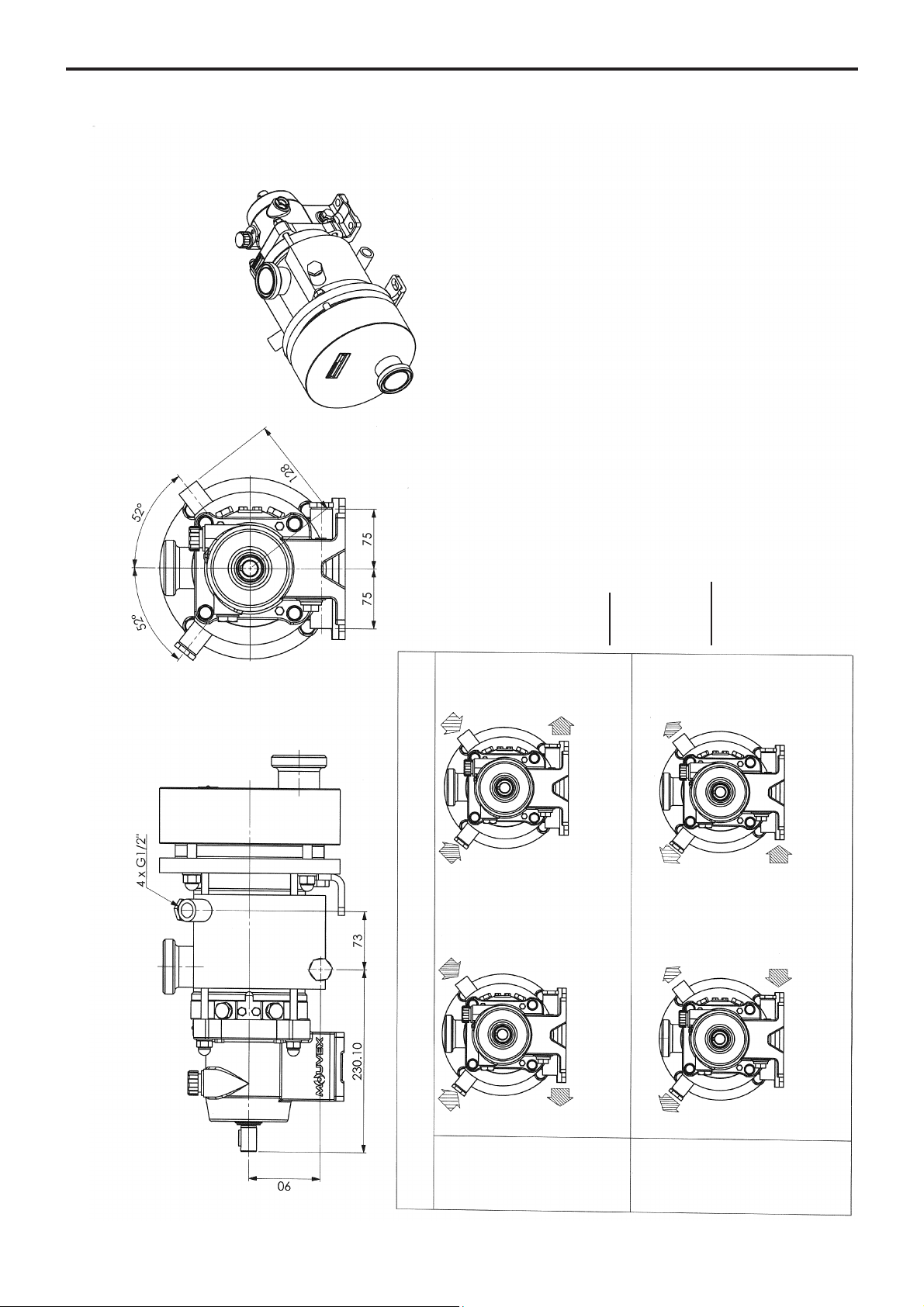
2. OVERALL DIMENSIONS (continued)
SLS4 i - SLS8 i
with heating jacket
JACKET CONNECTION
The entry connection may be connected to one or two points.
NOTICE :
For the other sides, see the specific overall dimension plan for the connection.
Maximum jacket temperature : FKM and FEP encapsulated FKM seals : 180°C
Maximum pressure jacket : see TECHNICAL CHARACTERISTICS.
CAUTION
:
The pumped product must not exceed the temperature of 100°C.
On jacketed pumps, suction port can only be in position 2 (top).
Positions 1 and 3 (sides) are not possible.
FOR ATEX PUMPS, SEE INSTRUCTIONS NR 1071.
STEAM
LIQUID
The outlet connection may be connected to one or two points.
If it is done at 1 point, purge the air at the second point.
OR
OR
7/31
NT 1004-E00 02 18 SLS4 i - SLS8 i e
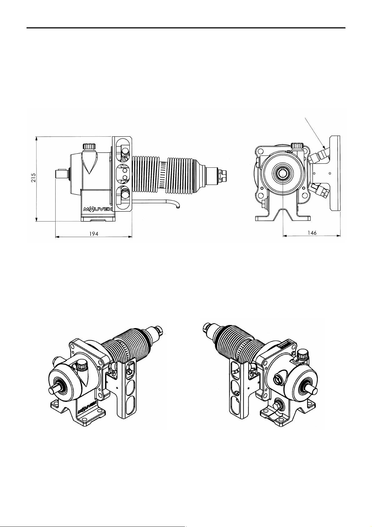
2. OVERALL DIMENSIONS (continued)
NOTA :
The monitoring system is mounted on the right in standard version but can be mounted on the left if the suction port
of the pump is on the same side.
Setting of detection levels is done in factory and do not have to be modified.
For other dimensions, report to pump dimensional drawing.
The dismantling of the transmission could be done only in factory.
Transmission SL 4 i - SL 8 i
with BMS (Bellows Monitoring System)
Connector M15
5 pins
BMS right mounted BMS left mounted
8/31
NT 1004-E00 02 18 SLS4 i - SLS8 i e
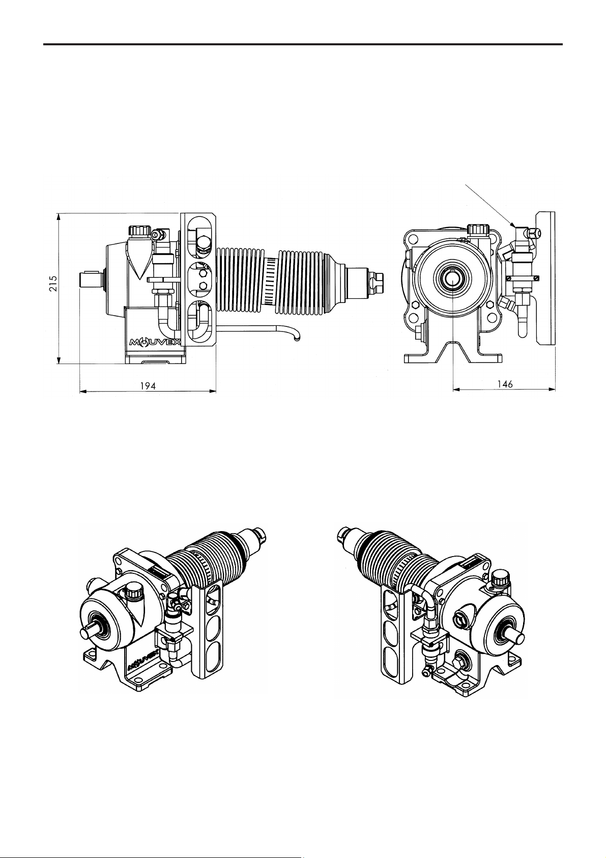
2. OVERALL DIMENSIONS (continued)
NOTA :
The monitoring system is mounted on the right in standard version but can be mounted on the left if the suction port
of the pump is on the same side.
Setting of detection levels is done in factory and do not have to be modified.
For other dimensions, report to pump dimensional drawing.
The dismantling of the transmission could be done only in factory.
Connector M15
5 pins
Transmission SL 4 i - SL 8 i
with ATEX BMS (Bellows Monitoring System)
BMS right mounted BMS left mounted

9/31
NT 1004-E00 02 18 SLS4 i - SLS8 i e
3.1 Installation design
3.1.1 Pump
To obtain the service expected from a MOUVEX pump,
regarding both performance and longevity, it is vital that
the type of pump, its speed and the materials used for its
construction are determined as a function of the pump
output, its installation and operating conditions.
You can contact our Technical Services at any time to
ask for the information you require.
3.1.2 Pipe
Suction pipe length
Length should be as short as possible.
Suction pipe diameter
Diameter must be at least equal to pump port diameter
and even more if required by pumping conditions.
Suction pipe configuration
Check tightness to avoid accidental air intake.
--------------------------------------------------------------------
Pipe alignment and supporting
Pump must not support piping nor endure stress resulting from piping weight or dilatation effects. For latters,
expansion loops should be included.
Not recommended
To be avoided if possible
Recommended
3. INSTALLATION
R=3xDminimum
L=10xDminimum
10/31
NT 1004-E00 02 18 SLS4 i - SLS8 i e
Pipe equipment
• Place valves close to the pump to avoid draining pipe
during maintenance operations. Preferably select full
bore ball or butterfly valves.
Pressure connections on pump suction and discharge
are recommended for settings and controls.
Make sure piping, vessels valves and other installation
devices are carefully cleaned before mounting.
• MOUVEX pumps are self priming. However, if line
emptying should be avoided and/or if suction lift is high,
a foot valve can be added.
• If pumped liquid presents a risk of in pipe solidification
and potential dilatation, low points on the pipe should
be avoided or equipped with drain valve.
• If installation is heated, it must be designed so that fluid
dilatation can evacuate through piping. Therefore fluid
contained in piping must be heated before fluid contained
in the pump. Also check that a heated pump is not isolated by closed valves.
The SL Series pump is a selfpriming volumetric PD
pump. Therefore, the pump must not run on a circuit with
a closed valve. This is valid both for the suction circuit
and for the discharge circuit.
3.2 Orientation of the pump ports
The suction and discharge ports may be oriented in
various positions.
If the ports positions needs to be changed at any time,
see the corresponding paragraph.
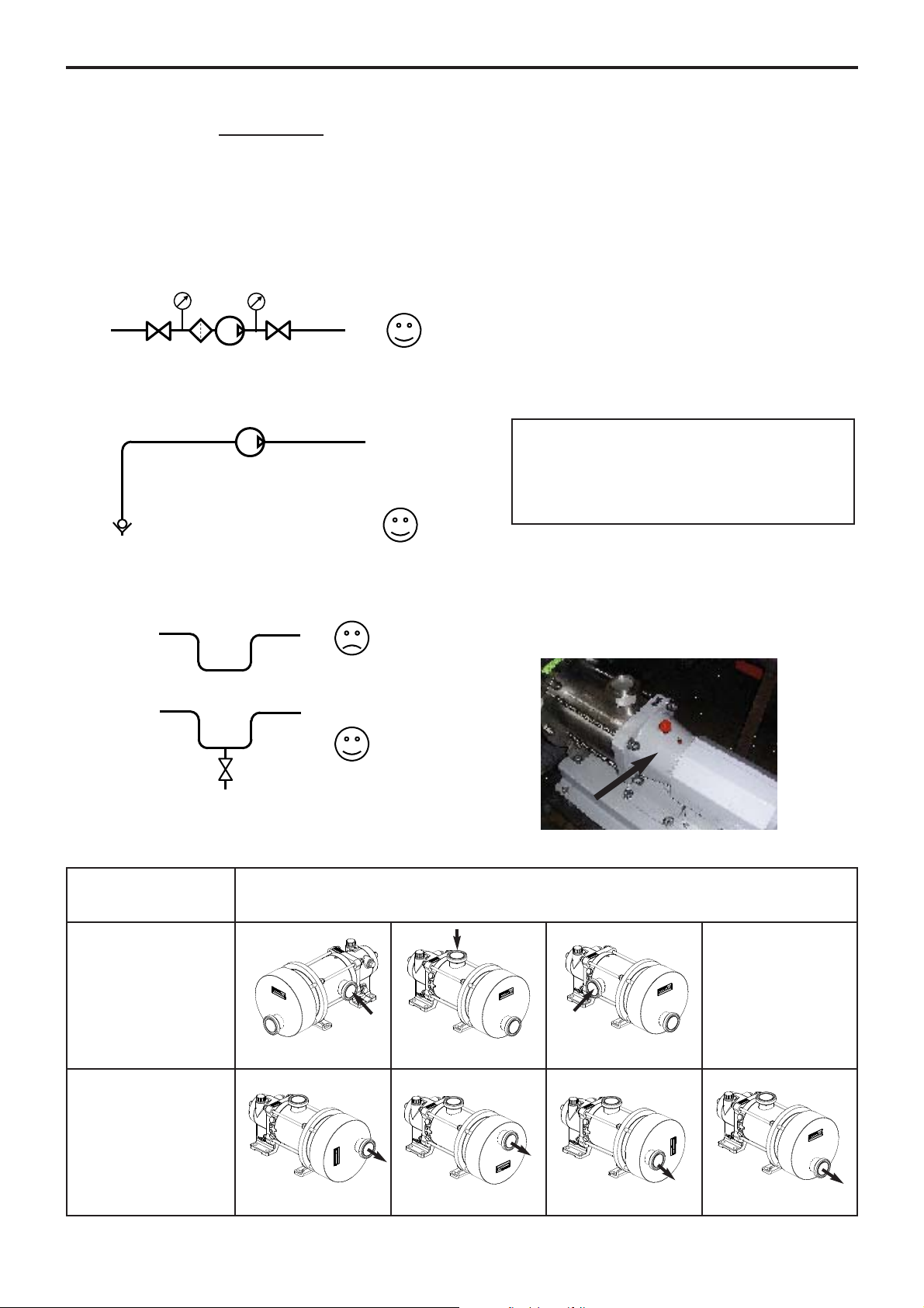
3.3 Direction of rotation
When looking at the shaft, the rotation will be clockwise.
When looking at the front cover, the direction of rotation
will be anti-clockwise. An arrow situated on the bearing
housing indicates the correct direction of rotation.
NOTICE
SL Series pumps remains drainable whatever
position is chosen for the inlet port, but the
outlet port must be at the bottom (position 4) to
keep the self-draining capability.
3. INSTALLATION (continued)
POSSIBLE POSITIONS
Pumps with heating jacket : see § OVERALL DIMENSIONS - Heating jacket
SUCTION
1 2 STANDARD 3 4
DISCHARGE
1 2 3 4 STANDARD
 Loading...