

Mouvex SLS24 i, SLS36 i, C4 A, C4 A HT, C8 A Maintance Manual
...
SLS24 i - SLS36 i
PUMPS
INSTALLATION
OPERATION
MAINTENANCE
INSTRUCTIONS 1004-H00 e
Section 1004
Effective October 2016
Replaces June 2016
Original instructions
Дистрибутор:
България, София 1528, ул."Поручик Неделчо Бончев" 3, eт.5

2/29
NT 1004-H00 10 16 SLS24 i - SLS36 i e
ECCENTRIC PISTON PUMP
MOUVEX PRINCIPLE
SAFETY INSTRUCTIONS, STORAGE, INSTALLATION AND MAINTENANCE
SLS24 i - SLS36 i MODELS
TECHNICAL CHARACTERISTICS
- Maximum pump speed : 460 rpm
- Running temperatures :
• ambient .........................................................-15°C → + 40°C
• continuous pomped product .........................-15°C → +100°C
• washing / rinsing / sterilisation product......... 0°C → +121°C
• heating fluid (jacket) .....................................-15°C → +180°C
- Maximum suction pressure :
• In normal use, the suction pressure must be higher than the required
NPSH and less than 2 barg (29 psig).
• During CIP/SIP of the pump, the suction pressure must not exceed
3 barg (43,5 psig).
• Pump stopped, the pressure must not exceed 6 barg (87 psig).
- Acceptable maximal differential pressure :
• SLS24 i . . . . .9 bar (130,5 psi)*
• SLS36 i . . . . .6 bar (87 psi)*
- Maximum pressure jacket : 5 barg (72,50 psig)
- Cylinder capacity :
• SLS24 i . . . . .0,946 litre
• SLS36 i . . . . .1,420 litre
* When the pump works with an inlet gauge pressure less than zero, the
maximum outlet pressure will be calculated as if the inlet pressure is
equal to zero.
USED PRESSURE UNITS
Unit without suffix :
Differential pressure, for example, pressure difference between
equipment suction and discharge.
Unit with suffix
"a" :
Absolute pressure.
Unit with suffix
"g" :
Gauge pressure, given regarding to atmospheric pressure
(~101325 Pa, taken at 1 bar / 14,5 psi in this IOM).
Pompe
P
asp
P
re
f
Psuc
Pdis
Pump
Example :
Psuc = -0,2 barg = 0,8 bara
Pdis = 8,8 barg = 9,8 bara
∆P = Pdis - Psuc = 9 bar
TABLE OF CONTENTS Page
1. OVERALL DIMENSIONS . . . . . . . . . . . . . . . . . . . . . . . . . .3
2. INSTALLATION . . . . . . . . . . . . . . . . . . . . . . . . . . . . . . . . .8
2.1 Installation design . . . . . . . . . . . . . . . . . . . . . . . . . . . . .8
2.2 Orientation of the pump ports . . . . . . . . . . . . . . . . . . . .9
2.3 Direction of rotation . . . . . . . . . . . . . . . . . . . . . . . . . . . .9
2.4 Protection of the pump installation . . . . . . . . . . . . . . . .9
2.5 Hoisting devices . . . . . . . . . . . . . . . . . . . . . . . . . . . . .10
2.6 Unit Assembly . . . . . . . . . . . . . . . . . . . . . . . . . . . . . . .10
3. UTILISATION . . . . . . . . . . . . . . . . . . . . . . . . . . . . . . . . .13
3.1 Noise level . . . . . . . . . . . . . . . . . . . . . . . . . . . . . . . . .13
3.2 Commissioning . . . . . . . . . . . . . . . . . . . . . . . . . . . . . .13
3.3 Dry running . . . . . . . . . . . . . . . . . . . . . . . . . . . . . . . . .13
3.4 Pump stop . . . . . . . . . . . . . . . . . . . . . . . . . . . . . . . . . .13
3.5 Scrapping . . . . . . . . . . . . . . . . . . . . . . . . . . . . . . . . . .13
4. CLEAN IN PLACE (CIP) & STERILISATION IN PLACE
(SIP) . . . . . . . . . . . . . . . . . . . . . . . . . . . . . . . . . . . . . . . .14
4.1 General . . . . . . . . . . . . . . . . . . . . . . . . . . . . . . . . . . . .14
4.2 CIP circuit recommended . . . . . . . . . . . . . . . . . . . . . .14
4.3 Pumps arranged in series . . . . . . . . . . . . . . . . . . . . . .14
4.4 Pumps arranged in parallel . . . . . . . . . . . . . . . . . . . . .15
4.5 Successive cycles . . . . . . . . . . . . . . . . . . . . . . . . . . . .16
4.6 Sterilisation In Place (SIP) . . . . . . . . . . . . . . . . . . . . .16
5. MAINTENANCE . . . . . . . . . . . . . . . . . . . . . . . . . . . . . . . .16
5.1 Necessary tools . . . . . . . . . . . . . . . . . . . . . . . . . . . . .16
6. OPENING OF THE PUMP . . . . . . . . . . . . . . . . . . . . . . . .17
6.1 Assembly / Dismantling . . . . . . . . . . . . . . . . . . . . . . . .17
6.2 Checking of parts . . . . . . . . . . . . . . . . . . . . . . . . . . . .18
7. ASSEMBLY OF CYLINDER/PISTON . . . . . . . . . . . . . . . .20
8. PROTECTION OF THE BELLOWS . . . . . . . . . . . . . . . . . .21
9. CHANGING THE LIP SEAL . . . . . . . . . . . . . . . . . . . . . . .23
10. CHANGING THE ORIENTATION OF THE PORTS . . . . .24
10.1 Discharge port . . . . . . . . . . . . . . . . . . . . . . . . . . . . . .24
10.2 Suction port . . . . . . . . . . . . . . . . . . . . . . . . . . . . . . . .24
11. DRAINING OF BEARING . . . . . . . . . . . . . . . . . . . . . . . .25
12. OPTIONS . . . . . . . . . . . . . . . . . . . . . . . . . . . . . . . . . . .25
12.1 Bellows monitoring system . . . . . . . . . . . . . . . . . . . .25
13. STORAGE . . . . . . . . . . . . . . . . . . . . . . . . . . . . . . . . . . .26
13.1 Short duration (≤ 1 month) . . . . . . . . . . . . . . . . . . . .26
13.2 Long duration (> 1 month) . . . . . . . . . . . . . . . . . . . .26
13.3 Restarting . . . . . . . . . . . . . . . . . . . . . . . . . . . . . . . . .26
14. TROUBLESHOOTING . . . . . . . . . . . . . . . . . . . . . . . . . .27
15. CERTIFICATE OF CONFORMITY . . . . . . . . . . . . . . . . .29
Definition of safety symbols
This is a SAFETY ALERT SYMBOL.
When you see this symbol on the product, or in the manual,
look for one of the following signal words and be alert to the
potential for personal injury, death or major property damage.
Warns of hazards that WILL cause serious personal injury,
death or major property damage.
Warns of hazards that CAN cause serious personal injury,
death or major property damage.
Warns of hazards that CAN cause personal injury or property
damage.
NOTICE
Indicates special instructions which are very important and
must be followed.
DANGER
WARNING
CAUTION
3/29
NT 1004-H00 10 16 SLS24 i - SLS36 i e
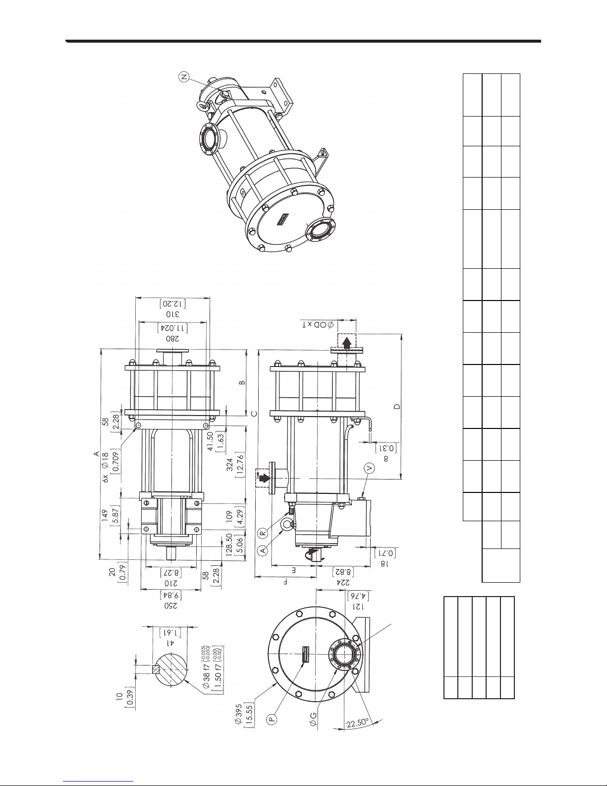
1. OVERALL DIMENSIONS
SLS24 i - SLS36 i
with flanges
M x ØL on ØK
Lifting ring
Pump plate
Filling / Breather
Draining
Oil level
A
P
R
V
N
DN A B C
ØG
EF
D
ØOD x T
M
(no unit)
ØL ØK
Masse -kg-
(Weight -lb-)
80 879 276 533,5 133 187 214,5 561 85 x 2,00 8 11 112 185
[3,15] [34,606] [10,866] [21,004] [5,236] [7,362] [8,445] [22,087] [3,346 x 0,079] - [0,433] [4,409] [408]
80 905,5 302,5 560 133 187 214,5 577,5 85 x 2,00 8 11 112 200
[3,15] [35,65] [11,909] [22,047] [5,236] [7,362] [8,445] [22,736] [3,346 x 0,079] - [0,433] [4,409] [441]
DIN 11864
BF-A
SLS24i
SLS36i

1. OVERALL DIMENSIONS (continued)
4/29
NT 1004-H00 10 16 SLS24 i - SLS36 i e
DN A B C D E F
Masse -kg-
(Weight -lb-)
76 879 276 533,5 566,5 187 220 76,1 x
1,6
185
[2,992] [34,606] [10,866] [21,004] [22,303] [7,362] [8,661] [2,996 x
0,063]
[408]
76 905,5 302,5 560 593 187 220 76,1 x
1,6
200
[2,992] [35,65] [11,909] [22,047] [23,346] [7,362] [8,661] [2,996 x
0,063]
[441]
76 879 276 533,5 566,5 187 220 76,7 x
1,9
185
[2,992] [34,606] [10,866] [21,004] [22,303] [7,362] [8,661] [3,02 x
0,075]
[408]
76 905,5 302,5 560 593 187 220 76,7 x
1,9
200
[2,992] [35,65] [11,909] [22,047] [23,346] [7,362] [8,661] [3,02 x
0,075]
[441]
76 879 276 533,5 566,5 187 197 76,20 x
1,651
185
[2,992] [34,606] [10,866] [21,004] [22,303] [7,362] [7,756] [3 x
0,065]
[408]
76 905,5 302,5 560 593 187 197 76,20 x
1,651
200
[2,992] [35,65] [11,909] [22,047] [23,346] [7,362] [7,756] [3 x
0,065]
[441]
80 879 276 533,5 566,5 187 220 87 x
3
185
[3,15] [34,606] [10,866] [21,004] [22,303] [7,362] [8,661] [3,425 x
0,118]
[408]
80 905,5 302,5 560 593 187 220 87 x
3
200
[3,15] [35,65] [11,909] [22,047] [23,346] [7,362] [8,661] [3,425 x
0,118]
[441]
Clamp
ASME-BPE
(2009)
SLS24i
SLS36i
DIN 11851
SLS24i
SLS36i
SMS 1145
SLS24i
SLS36i
Clamp
ISO 2852
SLS24i
SLS36i
ØOD x T
Lifting ring
Pump plate
Filling / Breather
Draining
Oil level
A
P
R
V
N
SLS24 i - SLS36 i
with connections
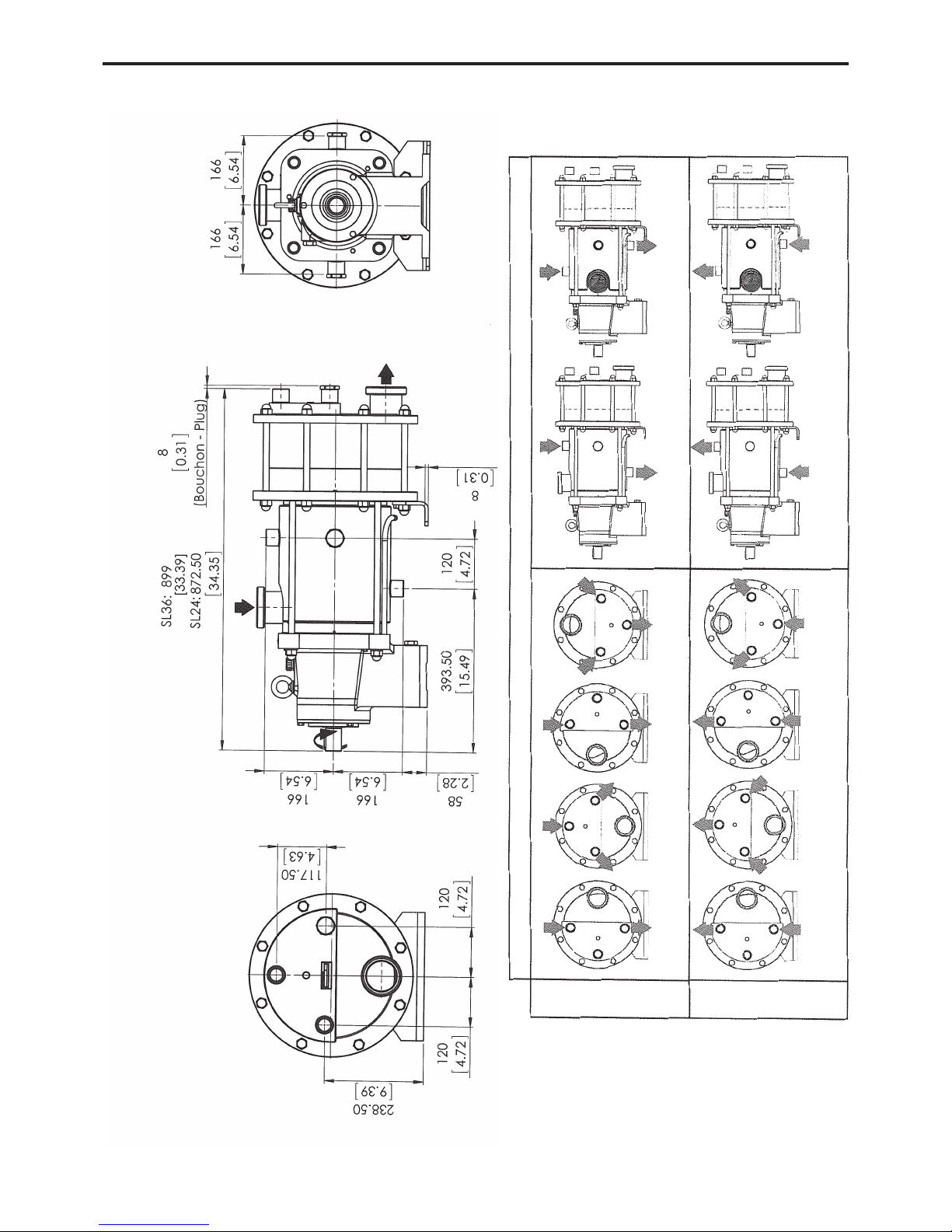
1. OVERALL DIMENSIONS (continued)
5/29
NT 1004-H00 10 16 SLS24 i - SLS36 i e
SLS24 i - SLS36 i
with heating jacket
FOR ATEX PUMPS, SEE INSTRUCTIONS NR 1071.
For the other sides, see the overall dimensions plan ‘SLS24 i - SLS36 i with
flanges/connections’.
Weight : + 8 kg
JACKET CONNECTION 1" B.S.P.F
LIQUID
STEAM
The entry connection may be connected to one or two points.
The outlet connection may be connected to one or two points.
If it is done at 1 point, purge the air at the second point.
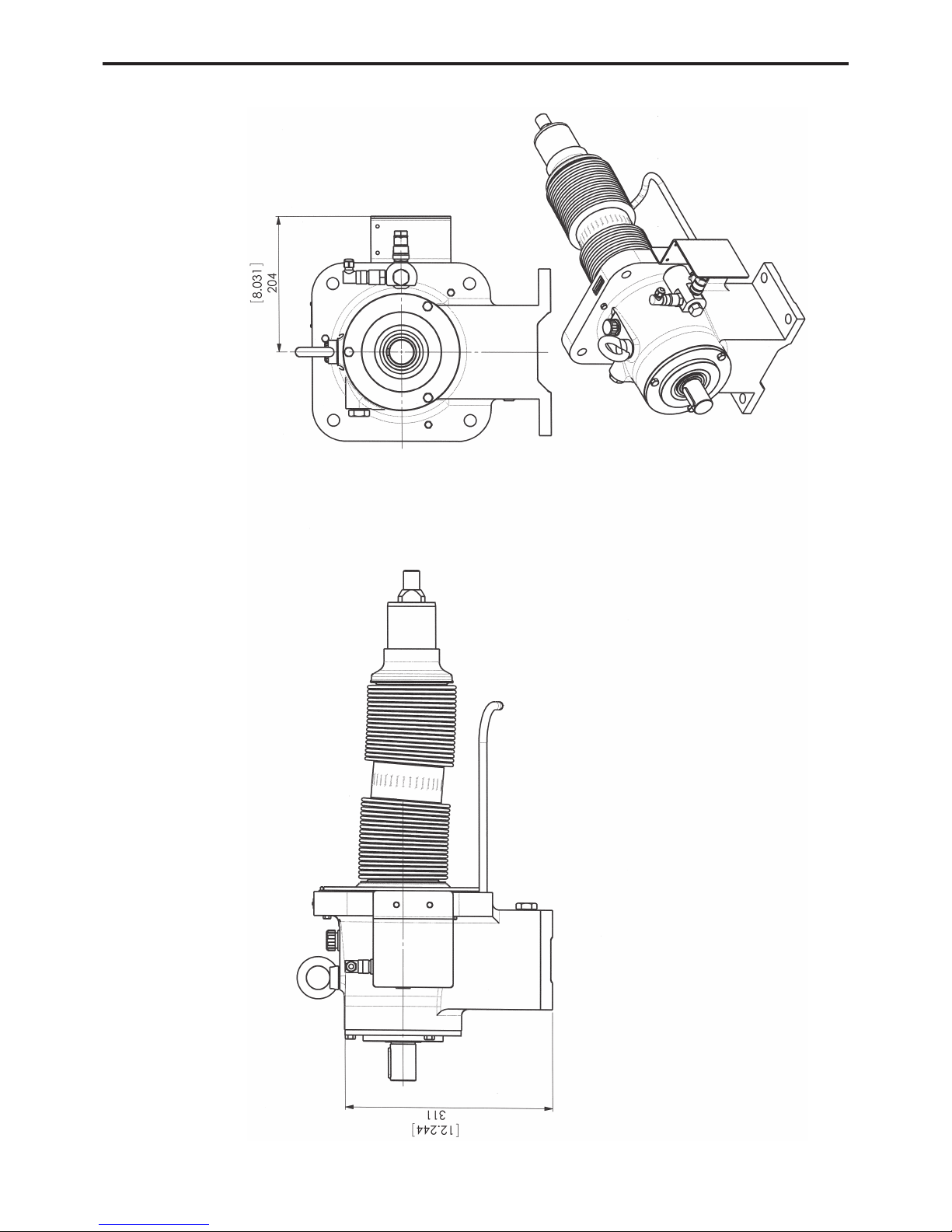
1. OVERALL DIMENSIONS (continued)
6/29
NT 1004-H00 10 16 SLS24 i - SLS36 i e
Bellows monitoring system
SLS24 i - SLS36 i
NOTA :
Setting of detection levels is done in factory and do not have to be modified.
For other dimensions, report to pump dimensional drawing.
The dismantling of the transmission could be done only in factory.
7/29
NT 1004-H00 10 16 SLS24 i - SLS36 i e
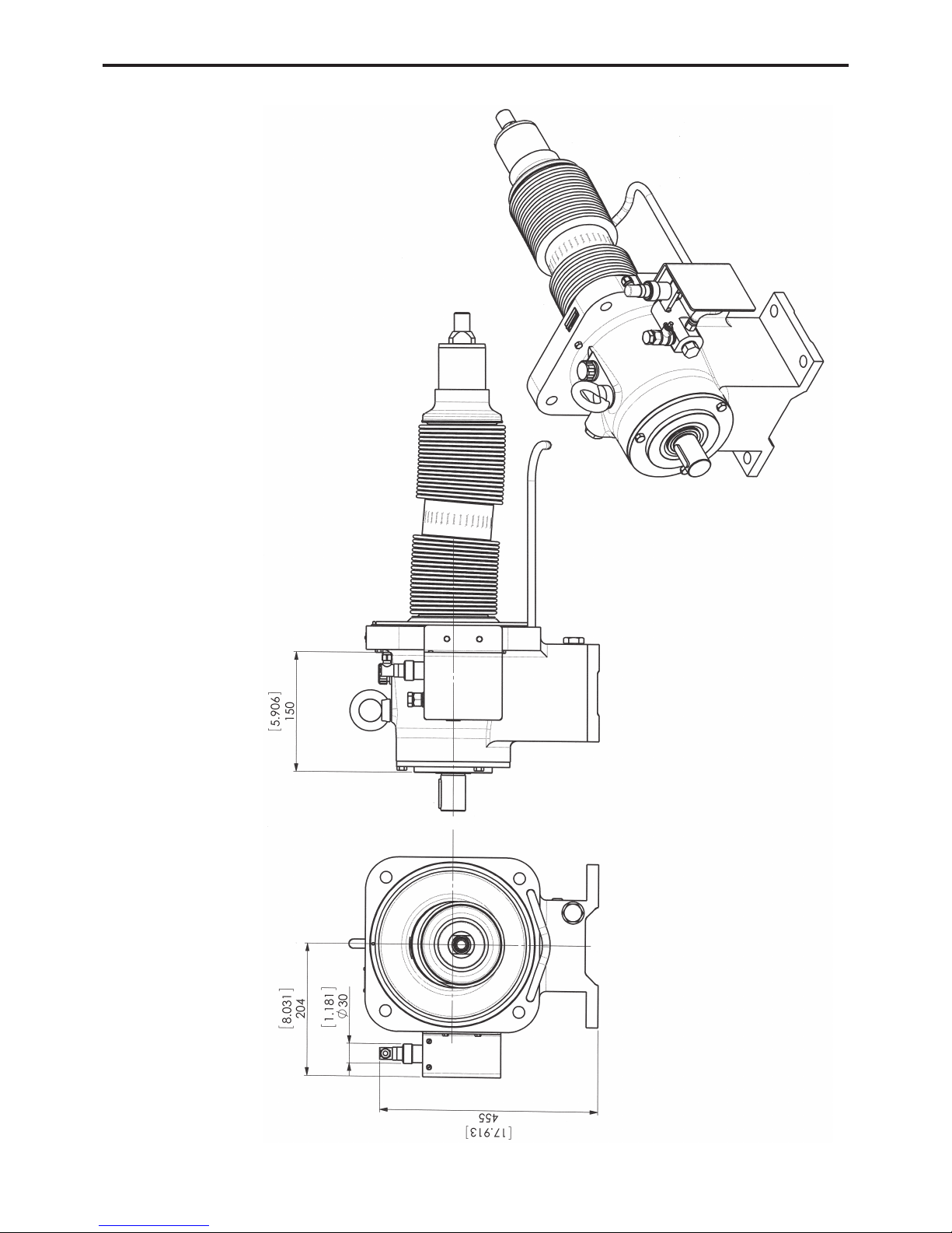
1. OVERALL DIMENSIONS (continued)
Bellows monitoring system ATEX
SLS24 i - SLS36 i
NOTA :
Setting of detection levels is done in factory and do not have to be modified.
For other dimensions, report to pump dimensional drawing.
The dismantling of the transmission could be done only in factory.

8/29
NT 1004-H00 10 16 SLS24 i - SLS36 i e
2.1 Installation design
2.1.1 Pump
To obtain the service expected from a MOUVEX pump,
regarding both performance and longevity, it is vital that
the type of pump, its speed and the materials used for its
construction are determined as a function of the pump
output, its installation and operating conditions.
You can contact our Technical Services at any time to
ask for the information you require.
2.1.2 Pipe
Suction pipe length
Length should be as short as possible.
Suction pipe diameter
Diameter must be at least equal to pump port diameter
and even more if required by pumping conditions.
Suction pipe configuration
Check tightness to avoid accidental air intake.
--------------------------------------------------------------------
L=10xDminimum
R=3xDminimum
Not recommended
To be avoided if possible
Recommended
2. INSTALLATION
POSSIBLE POSITIONS (pumps with heating jacket : see § OVERALL DIMENSIONS - Heating jacket)
ASPIRATION
DISCHARGE
STANDARD
STANDARD

9/29
NT 1004-H00 10 16 SLS24 i - SLS36 i e
Pipe alignment and supporting
Pump must not support piping nor endure stress resulting from piping weight or dilatation effects. For latters,
expansion loops should be included.
Pipe equipment
• Place valves close to the pump to avoid draining pipe
during maintenance operations. Preferably select full
bore ball or butterfly valves.
Pressure connections on pump suction and discharge
are recommended for settings and controls.
Make sure piping, vessels valves and other installation
devices are carefully cleaned before mounting.
• MOUVEX pumps are self priming. However, if line
emptying should be avoided and/or if suction lift is high,
a foot valve can be added.
• If pumped liquid presents a risk of in pipe solidification
and potential dilatation, low points on the pipe should
be avoided or equipped with drain valve.
• If installation is heated, it must be designed so that fluid
dilatation can evacuate through piping. Therefore fluid
contained in piping must be heated before fluid contained
in the pump. Also check that a heated pump is not isolated by closed valves.
The SLS Series pump is a selfpriming volumetric PD
pump. Therefore, the pump must not run on a circuit with a
closed valve. This is valid both for the suction circuit and
for the discharge circuit.
2.2 Orientation of the pump ports
The suction and discharge ports may be oriented in
various positions.
If the ports positions needs to be changed at any time,
see the corresponding paragraph.
2.3 Direction of rotation
An arrow situated on the bearing housing indicates the
correct direction of rotation.
When looking at the shaft, the rotation will be clockwise.
When looking at the front cover, the direction of rotation
will be anti-clockwise.
Verification of the correct rotation direction : Turn the
pump the wrong way is not dangerous for the pump.
2.4 Protection of the pump installation
• Before any start-up, during operation or complete stopping of the pump, make sure the valves are open
.
• During stop periods, with the pump full of product,
either the suction or discharge circuit must be left open
to enable expansion or contraction of the pumped product through reheating or cooling. If this instruction is
not complied with, The bellows may be damaged and
lead to premate failure.
• The bearing must be ventilate at all times, therefore the
breather mounted on the bearing must be re-used.
Never put the plug on.
NOTICE
SLS-Series pumps remains drainable whatever
position is chosen for the inlet port, but the
outlet port must be at the bottom (position 4)
to keep the self-draining capability.
2. INSTALLATION (continued)
 Loading...