

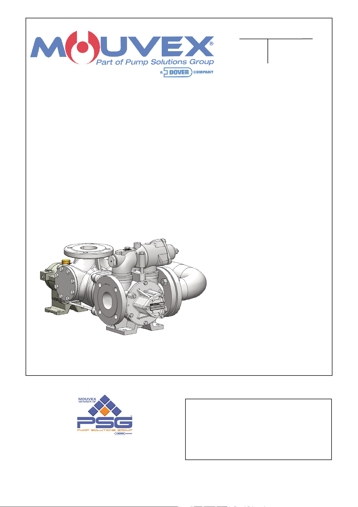
Mouvex SLP25 i Maintance Manual
PUMPS
INSTRUCTIONS 1007-A00 e
Section 1007
Effective November 2011
Replaces March 2011
Original instructions
INSTALLATION
OPERATION
MAINTENANCE
Your distributor :
Z.I. La Plaine des Isles - F 89000 AUXERRE - FRANCE
Tel. : +33 (0)3.86.49.86.30 - Fax : +33 (0)3.86.49.87.17
contact@mouvex.com - www.mouvex.com
SLP25 i S
ERIES
(manufactured from 2010 to 2013)

2/33
NT 1007-A00 11.11 SLP25 i series pumps e
VANE PUMPS
SAFETY, STORAGE, INSTALLATION AND MAINTENANCE INSTRUCTIONS
MODELS : SLP SERIES
SLP25 i
1. OVERALL DIMENSIONS . . . . . . . . . . . . . . . . . . . . . . . . . .3
2. INSTALLATION . . . . . . . . . . . . . . . . . . . . . . . . . . . . . . . . .7
2.1 Pump selection . . . . . . . . . . . . . . . . . . . . . . . . . . . . . . .7
2.2 Pipe diameter . . . . . . . . . . . . . . . . . . . . . . . . . . . . . . . .7
2.3 Piping assembly . . . . . . . . . . . . . . . . . . . . . . . . . . . . . .7
2.4 Direction of rotation . . . . . . . . . . . . . . . . . . . . . . . . . . . .8
2.5 Changing the direction of rotation . . . . . . . . . . . . . . . . .8
2.6 Protecting the installation against overpressure . . . . . .9
2.7 Cleaning . . . . . . . . . . . . . . . . . . . . . . . . . . . . . . . . . . . .9
2.8 Hoisting devices . . . . . . . . . . . . . . . . . . . . . . . . . . . . . .9
2.9 Installation of units . . . . . . . . . . . . . . . . . . . . . . . . . . .10
2.10 Alignment of motor/pump or reduction gearbox/pump
shafts . . . . . . . . . . . . . . . . . . . . . . . . . . . . . . . . . . . . .10
2.11 Electric motors . . . . . . . . . . . . . . . . . . . . . . . . . . . . . .11
2.12 Diesel engines drive . . . . . . . . . . . . . . . . . . . . . . . . .11
3. USE . . . . . . . . . . . . . . . . . . . . . . . . . . . . . . . . . . . . . . . . .12
3.1 Pumping hot or cold liquids . . . . . . . . . . . . . . . . . . . .12
3.2 Pump full of liquid when stopped . . . . . . . . . . . . . . . .12
3.3 Noise level . . . . . . . . . . . . . . . . . . . . . . . . . . . . . . . . .12
3.4 Starting-up the pump . . . . . . . . . . . . . . . . . . . . . . . . .12
3.5 Shutting down the pump . . . . . . . . . . . . . . . . . . . . . . .12
3.6 Storage . . . . . . . . . . . . . . . . . . . . . . . . . . . . . . . . . . . .13
3.7 Scrapping . . . . . . . . . . . . . . . . . . . . . . . . . . . . . . . . . .13
4. REQUIRED TOOLS AND TIGHTENING TORQUES . . . . .13
4.1 Necessary tools . . . . . . . . . . . . . . . . . . . . . . . . . . . . .13
4.2 Assembly torques . . . . . . . . . . . . . . . . . . . . . . . . . . . .13
5. OPENING AND CLOSING THE NON-DRIVE SIDE OF PUMP .14
5.1 Opening the base on the non-drive side . . . . . . . . .15
5.2 Checking the vanes . . . . . . . . . . . . . . . . . . . . . . . . . .15
5.3 Changing the bushing . . . . . . . . . . . . . . . . . . . . . . . . .16
5.4 Closing the non-drive side base . . . . . . . . . . . . . . . . .16
6. OPENING AND CLOSING THE DRIVE SIDE BASE . . . . .17
6.1 Dismantling / reassembling connection manifold . . . .18
6.2 Dismantling / reassembling transmission . . . . . . . . . .18
6.3 Dismantling the adaptation unit base . . . . . . . . . . . . .19
6.4 Changing the bushing in the adaptation base . . . . . .20
6.5 Dismantling inlet manifold . . . . . . . . . . . . . . . . . . . . . .21
6.6 Dismantling / reassembling transmission square driver .21
6.7 Changing the transmission and/or hub nose seal . . .22
6.8 Reassembly of vanes and pushrods . . . . . . . . . . . . .22
7. BYPASS . . . . . . . . . . . . . . . . . . . . . . . . . . . . . . . . . . . . .23
7.1 Bypass operation . . . . . . . . . . . . . . . . . . . . . . . . . . . .24
7.2 Bypass orientation . . . . . . . . . . . . . . . . . . . . . . . . . . .24
7.3 Bypass inversion . . . . . . . . . . . . . . . . . . . . . . . . . . . . .24
7.4 Bypass adjustment . . . . . . . . . . . . . . . . . . . . . . . . . . .25
7.5 Obtaining the flow . . . . . . . . . . . . . . . . . . . . . . . . . . . .25
7.6 Energy consumption . . . . . . . . . . . . . . . . . . . . . . . . . .25
7.7 Replacing the spring . . . . . . . . . . . . . . . . . . . . . . . . . .25
8. TRANSMISSION . . . . . . . . . . . . . . . . . . . . . . . . . . . . . . .26
8.1 Checking the bellows . . . . . . . . . . . . . . . . . . . . . . . . .27
8.2 Draining the bearing . . . . . . . . . . . . . . . . . . . . . . . . . .27
8.3 Transmission oil level control . . . . . . . . . . . . . . . . . . .27
8.4 Changing lip seals . . . . . . . . . . . . . . . . . . . . . . . . . . .28
9. MAINTENANCE . . . . . . . . . . . . . . . . . . . . . . . . . . . . . . . .29
9.1 Checking the condition of vanes and the pushrods . .29
9.2 Checking the condition of friction bushings . . . . . . . .29
10. TROUBLESHOOTING . . . . . . . . . . . . . . . . . . . . . . . . . .30
11. CERTIFICATE OF CONFORMITY . . . . . . . . . . . . . . . . .33
SUMMARY Page
TECHNICAL SPECIFICATIONS
•
Construction I : Stainless steel
• Non-food grade pump
• Maximum pump speed : 1000 rpm
• Maximum differential pressure : 12 bar relative
• Maximum suction pressure : 1,5 bar relative
• Max admissible transmission torque : 135 Nm
Pump n° :
Date of bringing into service :
This is a SAFETY ALERT SYMBOL
When you see this symbol on the product, or in the manual, look
for one of the following signal words and be alert to the potential for
personal injury, death or major property damage.
Warns of hazards that WILL cause serious personal injury,
death or major property damage
Warns of hazards that CAN cause serious personal injury,
death or major property damage.
Warns of hazards that CAN cause personal injury or property
damage.
NOTICE
Indicates special instructions which are very important and
must be followed.
SAFETY INFORMATIONS
WARNING
CAUTION
DANGER
3/33
NT 1007-A00 11.11 SLP25 i series pumps e
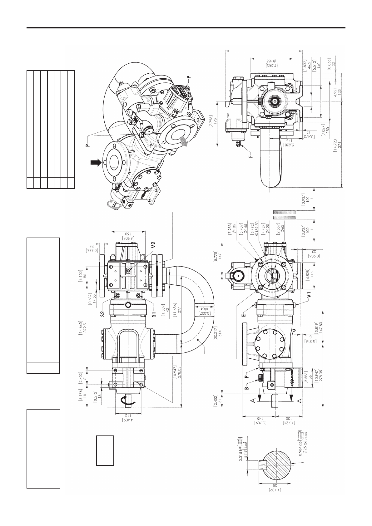
1. OVERALL DIMENSIONS
S1
S2
Temperature limiter device position
- Drilling Ø 8
- Always side of connecting manifold
S1 : outlet to the right*
S2 : outlet to the left*
4 holes Ø 13.5 [0.531]
Weight :
84 kg
2 x 4 holes Ø 18 [0.709]
at 90° (PN 16/20)
SLP25 i
4 holes Ø 14 [0.551]
335 with bypass
282 without bypass
Connecting manifold
* View from motor side
B
Plug (filling, breather)
E
Inlet tube vent
F
Bypass setting
J
Space for dismantling
P
Pump plate
V1
Inlet tube drain
V2
Pump drain
4/33
NT 1007-A00 11.11 SLP25 i series pumps e
1. OVERALL DIMENSIONS (continued)
NOTA :
Adjustments of the detection levels are made in the factory and must not be modified.
For other dimensions, refer to pump overall dimension drawing.
The transmission may only be dismantled in the factory.
CAUTION :
WRONG CONNECTION MAY
DESTROY THE SENSOR.
Connection diagram
Connector
Do not use S2
Normal operation
Rupture detection
Bellows monitoring system (pressure switch)
SL MECH D 135
5/33
NT 1007-A00 11.11 SLP25 i series pumps e
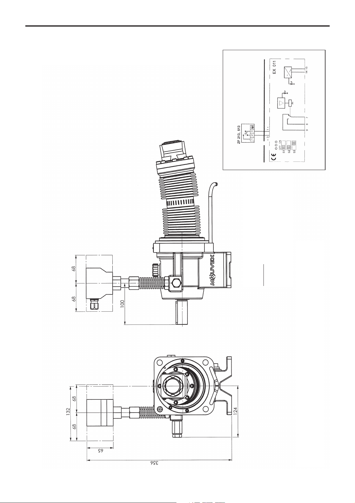
1. OVERALL DIMENSIONS (continued)
NOTA :
Adjustments of the detection levels are made in the factory and must not be modified.
For other dimensions, refer to pump overall dimension drawing.
The transmission may only be dismantled in the factory.
Bellows monitoring system (ATEX pressure switch)
SL MECH D 135
When the pressure drops, 3-2 opens.
CAUTION :
Wrong connection may :
- create a fire risk,
- make monitoring ineffective
- damage the sensor
Connection diagram
Ex-free Zone
Ex-Zone 1 or 2, 21 or 22
Supply
voltage
Outlet
Yellow
Green
Microswitch

6/33
NT 1007-A00 11.11 SLP25 i series pumps e
1. OVERALL DIMENSIONS (continued)
NOTA :
Adjustments of the detection levels are made in the factory and must not be modified.
For other dimensions, refer to pump overall dimension drawing.
The transmission may only be dismantled in the factory.
Double wall transmission with pressure gauge
SL MECH D 135

2.1 Pump selection
To obtain expected performance from MOUVEX series
SLP pump, regarding both performance and durability, it
is essential that the type of pump, its rotation speed and
the materials used in its construction are suitably determined in accordance with the pumped liquid and the installation and operating conditions.
OOur technical departments are at your disposal any
time for all necessary informations.
2.2 Pipe diameter
To obtain optimum conditions of use, it is important to check
the following recommendations regarding the sizing of
pipes :
• The pipe diameter will be determined depending on
their length and the flow and viscosity of liquid pumped,
so that pressure losses stay within the admissible limits
for the motor-driven pump unit. It is therefore difficult to
give general and precise instructions. However, it is
never a disadvantage to over-dimension pipe diameters, especially for the section on the inlet side.
• In the case of thin liquids and the piping on the discharge
side,one can generally allow a diameter equal to the
pump ports and a larger diameter for the piping on the
inlet side, if the value for the inlet power of the pump is
negative or especially high.
• For viscous liquids, special attention should be paid to
determining the pipe diameters. Indeed, the variation in
pressure loss is proportional to the viscosity and inversely proportional to the diameter exponent 4. A slight
reduction in the pipe diameter could therefore have
serious consequences on the pump’s operating conditions.
Our Technical Services are always available to provide you
with precise data if you give them accurate information
or, even better, the installation drawings.
2.3 Piping assembly
In order to achieve the best operating conditions, it is
important to take account of the following recommendations regarding piping assembly :
• The positioning of the pump in the transfer or recycling
circuit should always be chosen so as to reduce the
height and length of the piping as much as possible.
• Wherever possible, siphons and reverse slopes shouldbe avoided in the inlet piping.
• Particular care needs to be taken with the sealing on
the inlet side to prevent air entering.
• Pipe elbows must always have a large radius (more
than 3 times the diameter of the pipes) and must not be
mounted too close to the pump flanges (min. recommended distance : 10 times the pipe diameter), on both
the inlet and discharge sides.
• The pipes are supported and aligned with the pump so
as to avoid generating stress on the pump flanges.
Non-compliance with this instruction can lead to deformation of pump parts, misalignment of bearings and
accelerated material wear, even causing parts to break.
• For ease of any adjustments and checks, it is recommended that pressure tapping ports to which pressure/vacuum gauges may be fitted, are provided as close
as possible to the pump’s suction and discharge ports
(preferably at a distance of less than 5 times the pipe
diameter).
• If the suction head is especially high or if you want to
prevent the pipes emptying at shutdown, you can install
a foot valve. This should have a large diameter so as
not to generate additional pressure loss.
• We recommend placing valves as close as possible to
the pump ports to avoid having to drain the entire system
each time maintenance is carried out. These valves
should have the same diameter as the pipes and preferably be full bore models.
• All steps should be taken to prevent foreign bodies
from entering the pump (the use of a filter at the pump
intake is therefore strongly recommended).
• Before installing new pipes or tanks, check that they
are carefully cleaned to remove waste from welding,
rust, etc. which when carried through by the liquid
could cause deterioration to the pump.
• The pipes should be designed to allow thermal expansion/contraction (the use of flexible couplings or expansion loops is therefore recommended).
• If there is danger of the liquid freezing or solidifying, it
must be possible to drain the piping by installing taps
at the low points and air vents at the high points.
7/33
2. INSTALLATION
NT 1007-A00 11.11 SLP25 i series pumps e
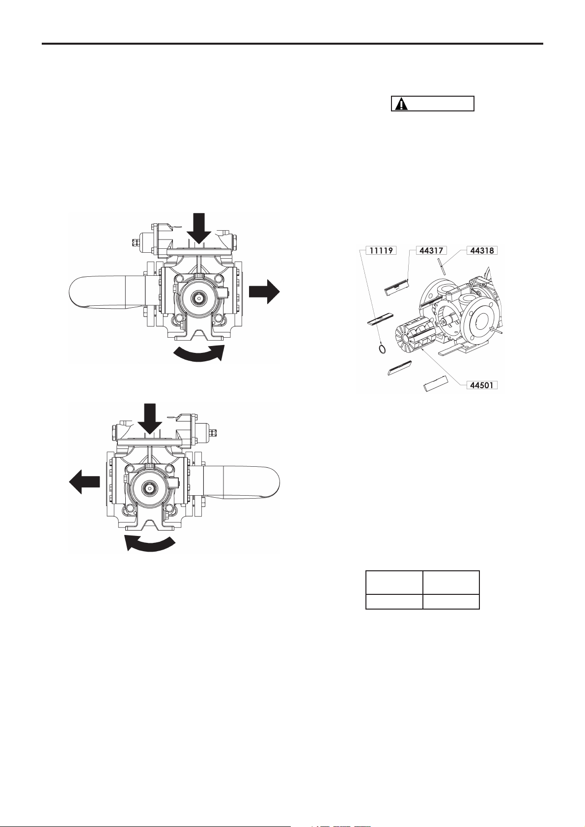
2.4 Direction of rotation
• In its standard configuration, the SLP series MOUVEX
pump is supplied as non reversible and with anticlockwise rotation.
NOTE :
ALL VIEWS IN THIS INSTRUCTION MANUALSHOW PARTS IN
THE STANDARD DIRECTION OF ROTATION.
The rule for the discharge side and the direction of rotation is as follows :
• For anticlockwise rotation (standard), the discharge
should be on the right side of the pump.
• For clockwise rotation, the discharge should be on the
left side of the pump.
In all cases, suction is from the top.
Operation in the opposite direction from that designed
for the pump is authorised nonetheless for a maximum
duration of 5 minutes as long as it remains below the
pressure limits (1,5 bar at the bellows).
The direction of rotation may be reversed :
• On request at the time the order is placed. In this case
the pump will be supplied with clockwise rotation.
• Or manually, referring to the following §.
2.5 Changing the direction of rotation
REGARDLESS OF THE INTERNAL DESIGN OF THE PUMP, THE
DIRECTION OF ROTATION SHOULD NOT BE CHANGED UNTIL
THE PUMP HAS COME TO A COMPLETE STOP, HAS COOLED
DOWN AND HAS BEEN DRAINED.
• Dismantle the connection manifold (see § DISMANTLING
/ASSEMBLING THE CONNECTION MANIFOLD).
• Dismantle the relief valve (see § ORIENTATION OF
BYPASS).
• Change the position of the rotor, the vanes and the
pushrods (for a pump with pushrods) : see § OPENING
AND CLOSING THE PUMP ON THE NON-DRIVE SIDE.
• Remove the vanes 44317 and the pushrods 44318.
• This may be carried out by removing the vanes 44317
horizontally and then the pushrods 44318 using a
screwdriver and pushing them to one of the pump outlet
ports.
• Follow the same procedure for the other vanes 44317.
• Remove the circlips 11119 (BE CAREFUL not to
scratch the shaft).
• Remove the rotor 44301, turn it over and re-assemble
it so that the rotor pushrods 44301 match up with the
holes in the shaft 44501.
• Place a suitable screw at the end of the shaft to pull it
and reveal the circlip groove.
• Replace the circlips 11119 taking care not to scratch the
shaft 44501.
• Re-assemble the vanes 44317 and the pushrods 44318
facing the correct direction (see § VANE CHECKS).
• Re-assemble the bypass facing the correct direction
(see § DIRECTION OF BYPASS).
• Re-assemble the connection manifold on the correct
side (see § DIRECTION OF ROTATION).
Screw
SLP25 M8
CAUTION
8/33
2. INSTALLATION (continued)
NT 1007-A00 11.11 SLP25 i series pumps e
2.6 Protecting the installation against overpressure
To protect the installation from any overpressure, the
use of a pressure relief safety device is recommended.
The standard pump is supplied fitted with a single internal relief valve to protect the system in one operating
direction. Its orientation therefore depends on the operating direction of the pump (refer to § RELIEF VALVE).
It is also possible to order the following option :
• Without relief valve
: the pump then has no other inbuilt
safety device. In this case, the pump must be protected
(for example with a pressure switch) to reduce any
overpressure.
If the rotation of the pump is to be used in both directions, (whatever the operating conditions), it is recommended to use a device that protects the pump from
overpressure when rotating in both directions (pressure
switch, etc.).
2.7 Cleaning
As the pumps are well-greased when supplied, it may be
necessary to clean them before starting them up.
They may be cleaned either by circulating an appropriate liquid or by dismantling the pump and carefully cleaning the internal parts (in which case, refer to § relating
to pump maintenance).
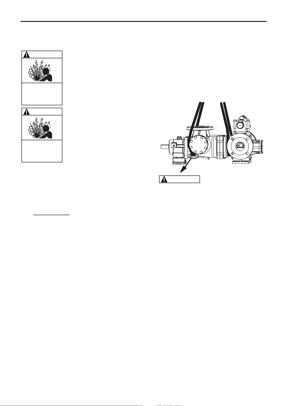
2.8 Hoisting devices
Hoisting points :
The strap must pass between the cradle and the
manifold.
• Use straps designed for the weight of the pump (see
overall dimension drawing).
WARNING
FAILURE TO INSTALL ADEQUATELY
SIZED PRESSURE RELIEF VALVE(S)
CAN CAUSE PROPERTY DAMAGE, PERSONAL INJURY OR DEATH.
WARNING
Hazardous pressure
can cause
personal injury
or property damage.
INCORRECT SETTINGS OF THE PRESSURE
RELIEF VALVE CAN CAUSE PUMP
COMPONENT FAILURE, PERSONAL
INJURY, AND PROPERTY DAMAGE.
WARNING
Hazardous pressure
can cause
personal injury
or property damage.
9/33
2. INSTALLATION (continued)
NT 1007-A00 11.11 SLP25 i series pumps e
10/33
2. INSTALLATION (continued)
2.9 Installation of units
The correct seating of a unit is essential for ensuring
smooth operation and longevity. The base must be flat,
level and sufficiently resistant to absorb stresses caused
by the motor-driven pump without being distorted
(concrete blocks must conform to the BAEL 91 standard).
Where the unit is fastened using anchor lugs or bolts, it
must be wedged carefully to prevent any distortion of the
chassis when tightening the bolts. Distortion of the chassis could cause prejudicial stress to the pump and the
drive device and put the coupling out of alignment, causing vibrations, noise and premature wear. Check that
the chassis is clear of the floor and off the support
plates.
Where the chassis is a one-piece unit in folded sheet
metal, it is recommended to leave a clear horizontal
space of around 50 cm between one end of the chassis
and the other to allow access to the locking nuts on the
pump, the reduction gearbox and the motor. In all cases,
the space around the pump unit should allow enough
room for dismantling the pump (refer to the overall
dimension drawing at the beginning for details of these
distances).
The chassis is equipped with an earth connection that
must be used to protect personnel and equipment.
The mounting base of the vane pump body and the
pump bearing are not on the same level (see § OVERALL DIMENSIONS). Different wedging must therefore
be used for these two bases.
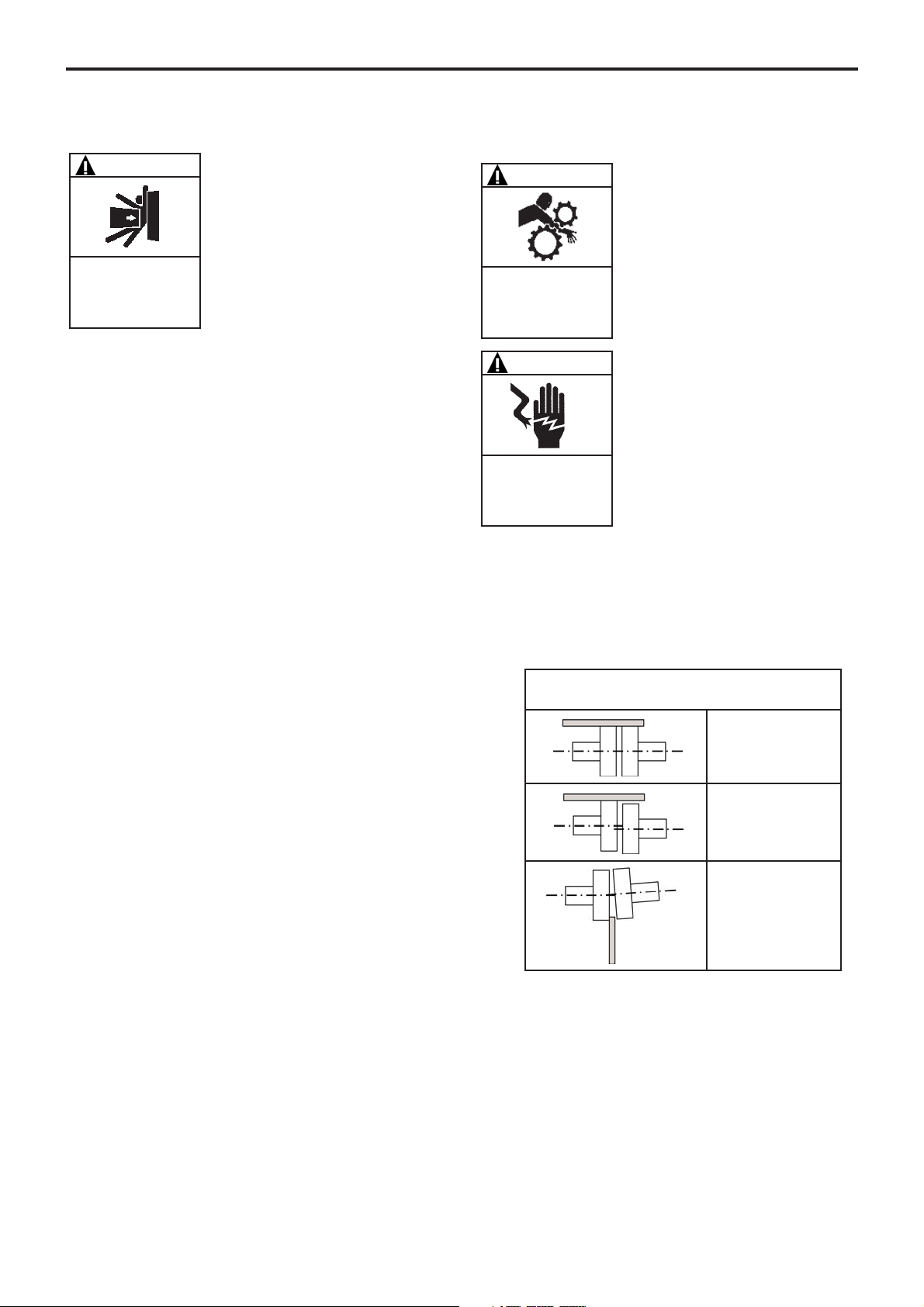
2.10 Alignment of motor/pump or reduction
gearbox/pump shafts
The motor and pump shafts are accurately aligned in the
factory before dispatch, but they must be checked automatically upon arrival and realigned if necessary. To align
the coupling and the shaft, use a straight edge to check
the offset and thickness gauges for angular misalignment.
The 3 figures below illustrate the operation and show the
admissible deviations :
It is important to check the alignment at each stage of
installation to ensure that no stresses are caused to the
unit or the pump :
• after fixing to the base.
• after attaching piping.
• after pump has operated at normal operating temperature.
Reminder :
The coupling must not be relied on to compensate for a
misalignment.
NEVER START A UNIT IF THE COUPLING ALIGNMENT IS
INCORRECT. THIS WILL INVALIDATE OUR WARRANTY.
Make this check for 4 points :
up - down - left - right
Correct
Out-of-parallelism
Angular defect
(maximum : 1°)
DISCONNECT THE ELECTRICITY SUPPLY
BEFORE ANY MAINTENANCE OPERATION.
WARNING
Dangerous voltage.
Can cause
injury and death.
OPERATION WITHOUT THE SHAFT
PROTECTOR CAN CAUSE SERIOUS
PERSONAL INJURY, MAJOR PROPERTY
DAMAGE, OR DEATH.
WARNING
Do not operate
without guard
in place.
BE CAREFUL WITH THE WEIGHT OF
THE PARTS WHEN THEY ARE BEING
REMOVED.
WARNING
The weight ot the parts can
be dangerous and may
provoke bodily injuries or
material damages.
NT 1007-A00 11.11 SLP25 i series pumps e
 Loading...