

Mouvex SLC1, SLC2, SLC3 Maintance Manual
SLC1 - SLC2 - SLC3
PUMPS
INSTRUCTIONS 1004-A00 e
Section 1004
Effective February 2013
Replaces January 2013
INSTALLATION
OPERATION
MAINTENANCE
Original instructions
Your distributor :
Z.I. La Plaine des Isles - F 89000 AUXERRE - FRANCE
Tel. : +33 (0)3.86.49.86.30 - Fax : +33 (0)3.86.49.87.17
contact@mouvex.com - www.mouvex.com
3, Poruchik Nedelcho Bonchev Str., . 5,1528 Soa, Bulgaria
tel: +359 2 973 27 67
e-mail: oce@daisglobal.eu
2/32
T 1004-A00 02.13 Pumps SLC1 - SLC2 - SLC3 e
1. OVERALL DIMENSIONS . . . . . . . . . . . . . . . . . . . . . . . . . .3
2. INSTALLATION . . . . . . . . . . . . . . . . . . . . . . . . . . . . . . . .17
2.1 Orientation of the pump ports . . . . . . . . . . . . . . . . . . .17
2.2 Direction of rotation . . . . . . . . . . . . . . . . . . . . . . . . . .17
2.3 Protection of the installation and the pump . . . . . . . .17
2.4 Unit Assembly . . . . . . . . . . . . . . . . . . . . . . . . . . . . . . .18
3. USE . . . . . . . . . . . . . . . . . . . . . . . . . . . . . . . . . . . . . . . . .20
3.1 Noise level . . . . . . . . . . . . . . . . . . . . . . . . . . . . . . . . .20
3.2 Commissioning . . . . . . . . . . . . . . . . . . . . . . . . . . . . . .20
3.3 Dry running . . . . . . . . . . . . . . . . . . . . . . . . . . . . . . . . .20
3.4 Stopping the pump . . . . . . . . . . . . . . . . . . . . . . . . . . .20
3.5 Bellows monitoring . . . . . . . . . . . . . . . . . . . . . . . . . . .20
3.6 Scrapping . . . . . . . . . . . . . . . . . . . . . . . . . . . . . . . . . .20
4. CLEAN IN PLACE (CIP) & STERILISATION IN PLACE
(SIP) . . . . . . . . . . . . . . . . . . . . . . . . . . . . . . . . . . . . . . .21
4.1 General . . . . . . . . . . . . . . . . . . . . . . . . . . . . . . . . . . . .21
4.2 CIP circuit recommended . . . . . . . . . . . . . . . . . . . . . .21
4.3 Pumps arranged in series . . . . . . . . . . . . . . . . . . . . . .21
4.4 Pumps arranged in parallel . . . . . . . . . . . . . . . . . . . . .22
4.5 Successive cycles . . . . . . . . . . . . . . . . . . . . . . . . . . .23
4.6 Sterilisation In Place (SIP) . . . . . . . . . . . . . . . . . . . . .23
5. MAINTENANCE . . . . . . . . . . . . . . . . . . . . . . . . . . . . . . . .24
5.1 Necessary tools . . . . . . . . . . . . . . . . . . . . . . . . . . . . .24
5.2 Pump disassembly . . . . . . . . . . . . . . . . . . . . . . . . . . .24
5.3 Checking the cylinder/piston couple . . . . . . . . . . . . . .26
5.4 Reassembling the pump . . . . . . . . . . . . . . . . . . . . . . .26
5.5 Transmission disassembly/reassembly . . . . . . . . . . . .28
6. CHECKING THE BELLOWS . . . . . . . . . . . . . . . . . . . . . . .28
7. DRAINING THE BEARING . . . . . . . . . . . . . . . . . . . . . . .29
8. OPTIONS . . . . . . . . . . . . . . . . . . . . . . . . . . . . . . . . . . . .30
8.1 Bellows monitoring system . . . . . . . . . . . . . . . . . . . . .30
8.2 Bellows monitoring system ATEX . . . . . . . . . . . . . . . .30
9. STORAGE . . . . . . . . . . . . . . . . . . . . . . . . . . . . . . . . . . . .31
9.1 Short duration (≤ 1 month) . . . . . . . . . . . . . . . . . . . . .31
9.2 Long duration (> 1 month) . . . . . . . . . . . . . . . . . . . . .31
9.3 Restarting . . . . . . . . . . . . . . . . . . . . . . . . . . . . . . . . . .31
10. CERTIFICATE OF CONFORMITY . . . . . . . . . . . . . . . . .32
TABLE OF CONTENTS Page
ECCENTRIC DISC PUMP
MOUVEX PRINCIPLE
SAFETY INSTRUCTIONS, STORAGE, INSTALLATION AND MAINTENANCE
MODELS : SLC1 - SLC2 - SLC3
TECHNICAL CHARACTERISTICS
- Maximum pump speed : 1000 rpm
- Maximum running temperature :
* continuous . . . . . . . . . . . . . . . . . . . . . . . . . .110°C
* washing/rinsing/sterilisation . . . . . . . . . . . . .121°C
- Maximum suction pressure :
• In normal use, the suction pressure must be higher than the
required NPSH and less than 1,5 barg (21,7 psig).
• During pump CIP/SIP, the suction pressure must not
exceed 3 barg (43,5 psig).
• With pump stopped, the pressure must not exceed 6 barg
(87 psig).
- Acceptable maximal differential pressure :
• SLC1 . . . . . . . . . . . . . .16 bar* (232 psi)
• SLC2 . . . . . . . . . . . . . .10 bar* (145 psi)
• SLC3 . . . . . . . . . . . . . . .6 bar* (87 psi)
- Maximum pressure jacket : 5 barg (72,50 psig)
- Displacement :
• SLC1 . . . . . . . . . . . . . . .0,017 liter
• SLC2 . . . . . . . . . . . . . . .0,034 liter
• SLC3 . . . . . . . . . . . . . . .0,051 liter
- Volume :
• Suction . . . . . . . . . . . . . . .0,43 liter
• Discharge . . . . . . . . . . . . .0,16 liter
• Total . . . . . . . . . . . . . . . . .0,59 liter (0,036 US gallons)
* When the pump works with an inlet gauge pressure less than zero, the
maximum outlet pressure will be calculated as if the inlet pressure is
equal to zero.
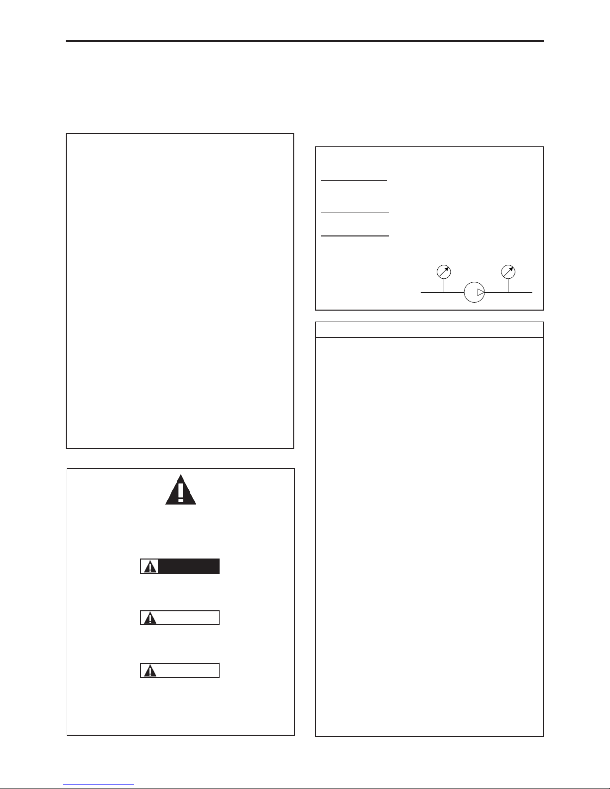
This is a SAFETY ALERT SYMBOL
When you see this symbol on the product, or in the manual, look
for one of the following signal words and be alert to the potential for
personal injury, death or major property damage.
Warns of hazards that WILL cause serious personal injury,
death or major property damage
Warns of hazards that CAN cause serious personal injury,
death or major property damage.
Warns of hazards that CAN cause personal injury or property
damage.
NOTICE
Indicates special instructions which are very important and
must be followed.
SAFETY INFORMATIONS
WARNING
CAUTION
DANGER
USED PRESSURE UNITS
Unit without suffix :
Differential pressure, for example, pressure difference between
equipment suction and discharge.
Unit with suffix
"a" :
Absolute pressure.
Unit with suffix
"g" :
Gauge pressure, given regarding to atmospheric pressure
(~101325 Pa, taken at 1 bar / 14,5 psi in this IOM).
Pompe
P
asp
P
re
f
Psuc
Pdis
Pump
Example :
Psuc = -0,2 barg = 0,8 bara
Pdis = 8,8 barg = 9,8 bara
∆P = Pdis - Psuc = 9 bar
3/32
T 1004-A00 02.13 Pumps SLC1 - SLC2 - SLC3 e
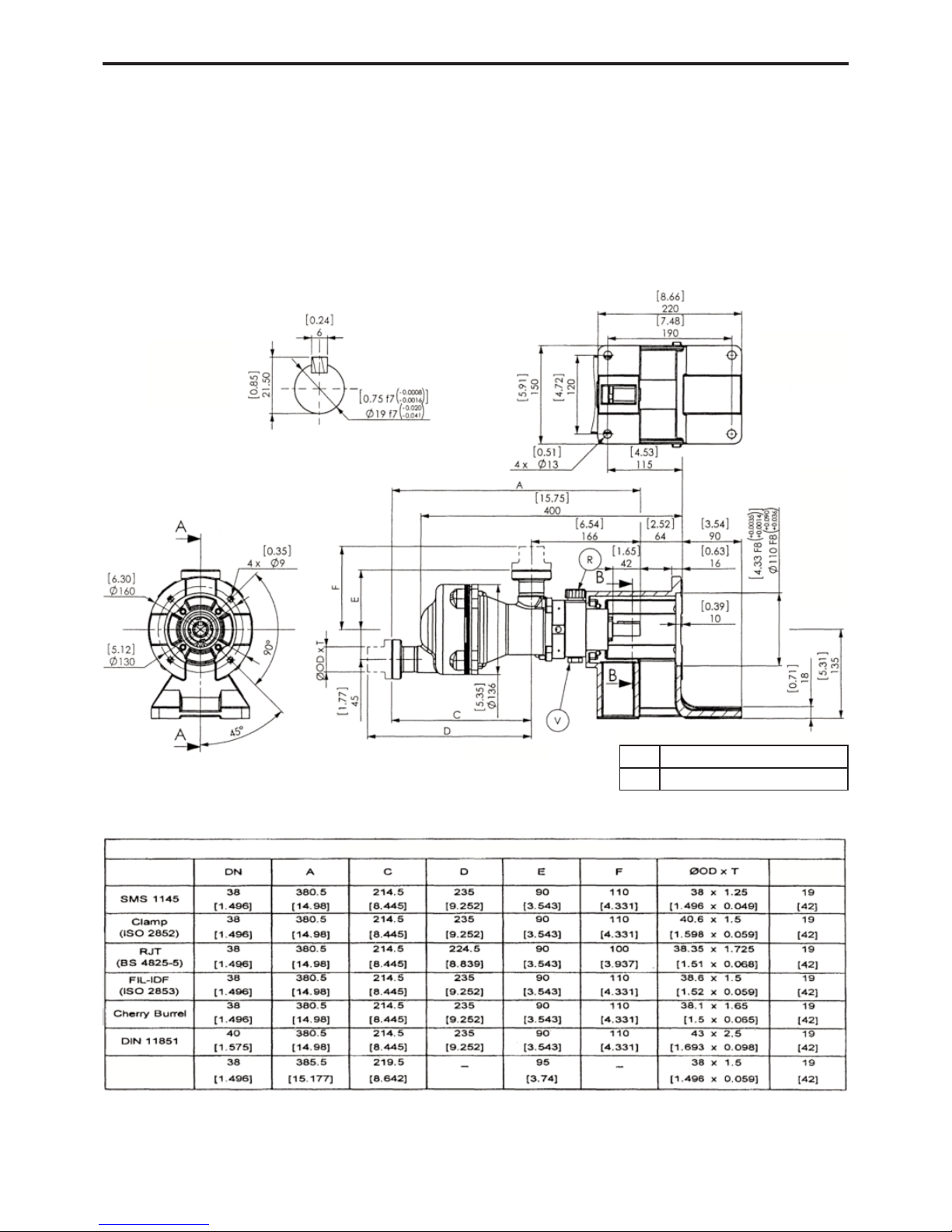
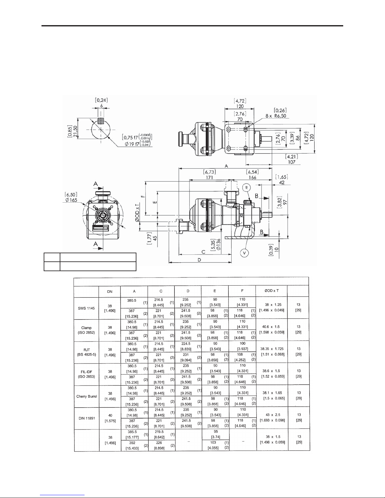
1. OVERALL DIMENSIONS
Pumps SLC1 - SLC2 - SLC3
with connections
Connections
* CAUTION : When welding the connections, the below should be protected.
Weight
kg [lb]
CROSS-SECTION A-A
CROSS-SECTION B-B
Filling / Breather
Draining
R
V
Smooth
end-fitting*
4/32
T 1004-A00 02.13 Pumps SLC1 - SLC2 - SLC3 e
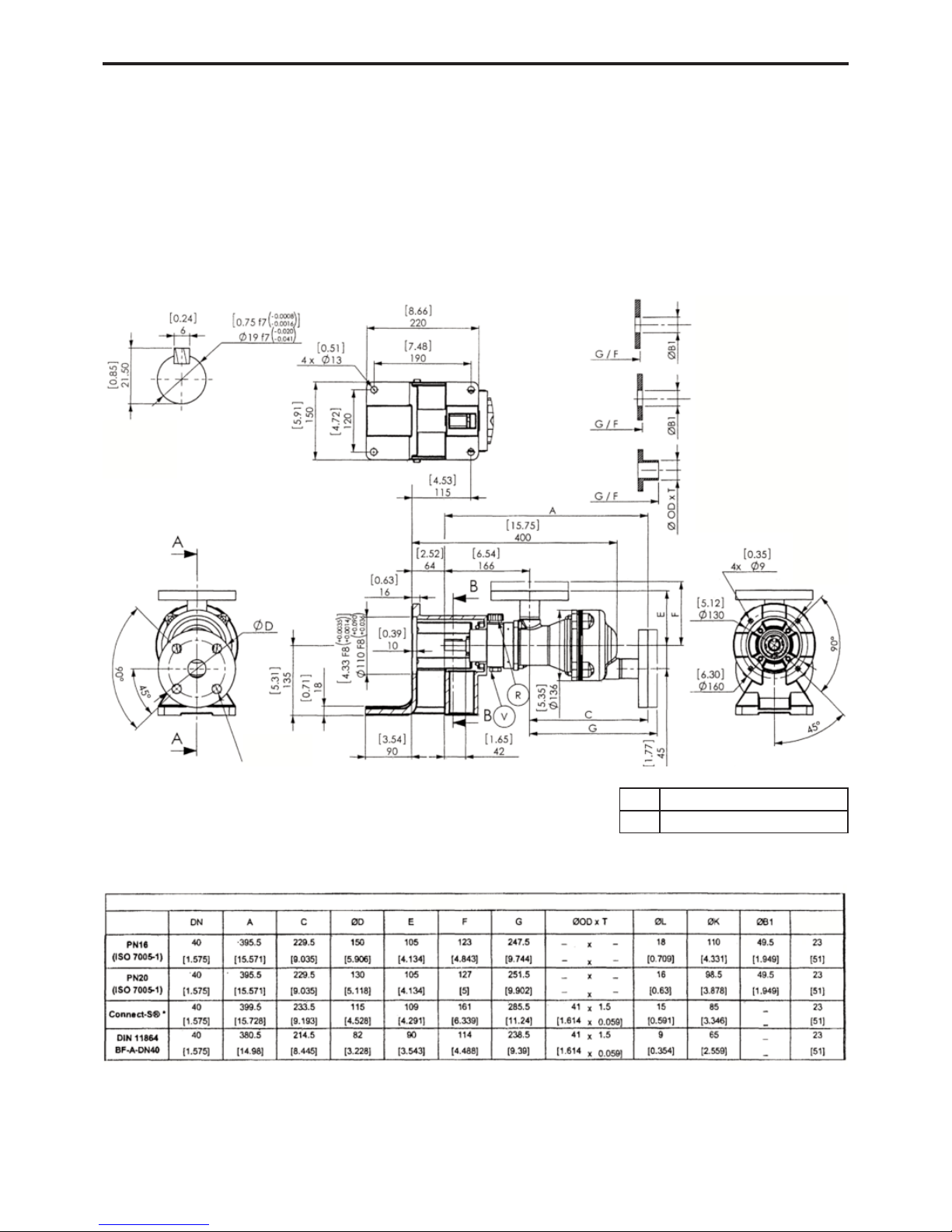
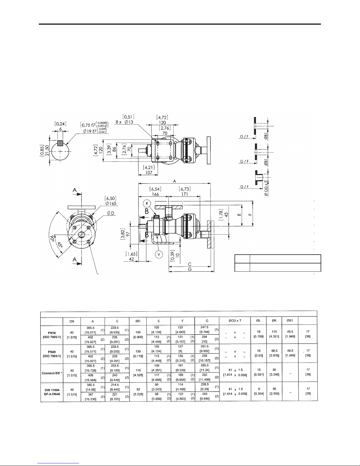
1. OVERALL DIMENSIONS (continued)
Pumps SLC1 - SLC2 - SLC3
with flanges
Flanges
PN16
Type 01
Fitted and welded pipe
PN20
Type 12B
Fitted and welded pipe
Others
Butt-welded pipe
* Connect-S®is a registered trademark owned by NEUMO.
CROSS-SECTION A-A
CROSS-SECTION B-B
4 x ØL on ØK
Weight
kg [lb]
Filling / Breather
Draining
R
V
5/32
T 1004-A00 02.13 Pumps SLC1 - SLC2 - SLC3 e
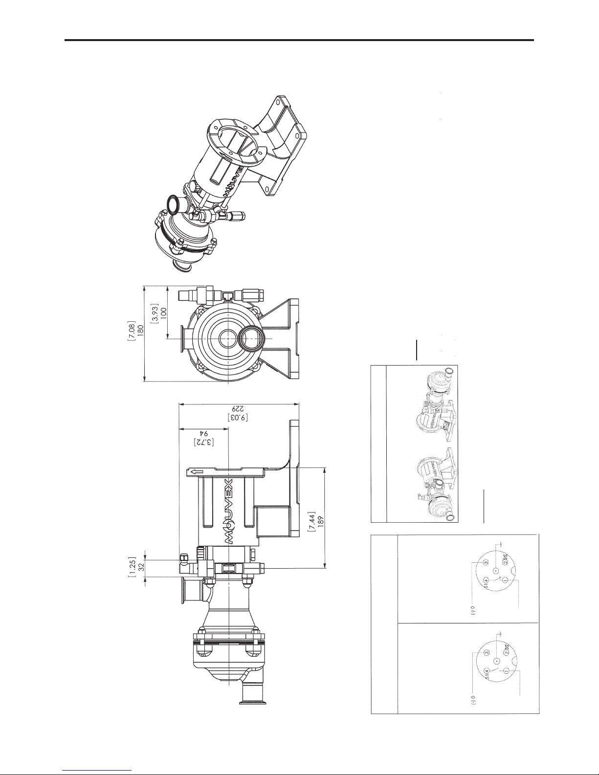
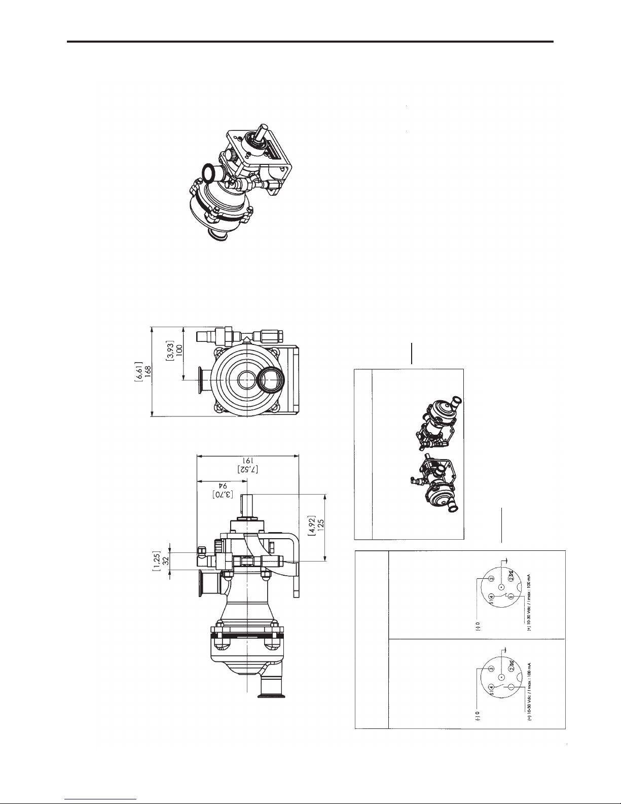
1. OVERALL DIMENSIONS (continued)
Pumps SLC1 - SLC2 - SLC3
with pressure switch
Standard pressure switch
Normal operation
Rupture detection
NOTE :
For the other dimensions, refer to the pump overall dimension drawing.
The detection bearings are adjusted in the plant and should not be modified.
The transmission may only be dismantled in the plant.
Pump weight : add 0,45 kg for the pressure switch.
CAUTION :
Incorrect connection can lead to :
- a flammability risk,
- ineffective monitoring,
- possible damage to the sensor.
lf the suction port is in position 1 :
The transmission is rotated by 180° and the detection
system is installed on the right (as seen from the shaft
end).
(+) 10-30 Vdc / I max : 100 mA
(+) 10-30 Vdc / I max : 100 mA
6/32
T 1004-A00 02.13 Pumps SLC1 - SLC2 - SLC3 e
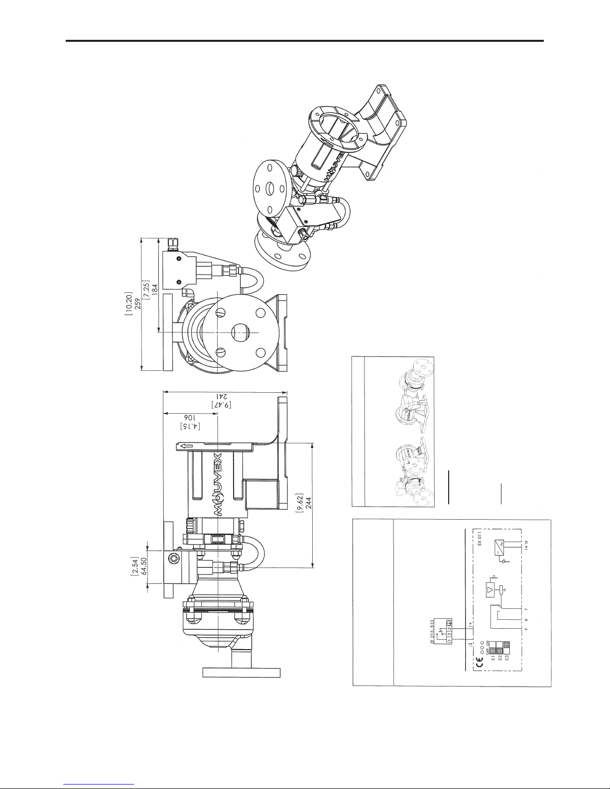
Pumps SLC1 - SLC2 - SLC3
with ATEX pressure switch
ATEX pressure switch
With falling pressure 3-2 opens.
NOTE
:
For the other dimensions, refer to the pump overall dimension drawing.
The detection bearings are adjusted in the plant and should not be modified.
The transmission may only be dismantled in the plant.
Pump weight : add 1 kg for the ATEX pressure switch.
CAUTION :
Incorrect connection can lead to :
- a flammability risk,
- ineffective monitoring,
- possible damage to the sensor.
lf the suction port is in position 1 :
The transmission is rotated by 180° and the detec-
tion system is installed on the right (as seen from
the shaft end).
Connection diagram
Ex-free Zone
Ex-Zone 1 or 2, 21 or 22
Microswitch
Supply voltageOutput
Yellow
Green
1. OVERALL DIMENSIONS (continued)
7/32
T 1004-A00 02.13 Pumps SLC1 - SLC2 - SLC3 e
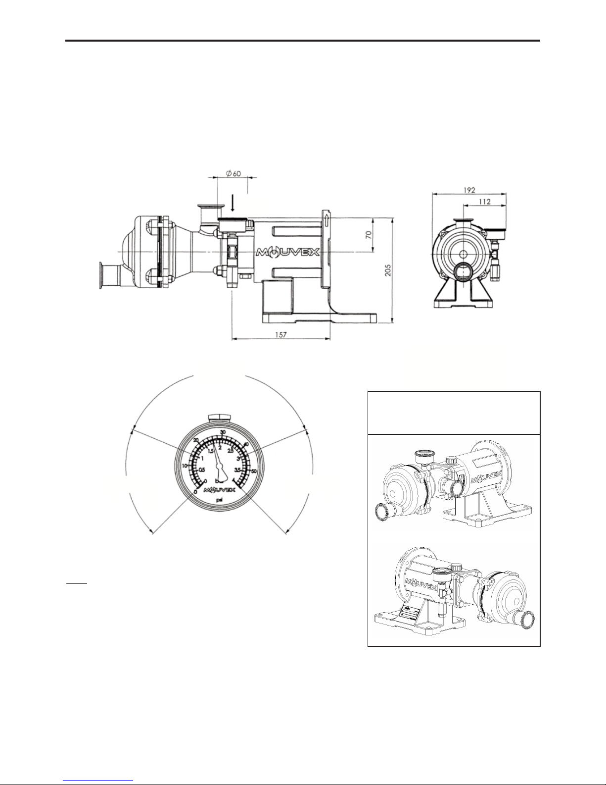
1. OVERALL DIMENSIONS (continued)
Pumps SLC1 - SLC2 - SLC3
with pressure gauge
Green zone
Red zone
Red zone
View F
NOTE :
For the other dimensions, refer to the pump overall dimension drawing.
The detection bearings are adjusted in the plant and should not be modified.
The transmission may only be dismantled in the plant.
Weight added to the pump : 0,5 kg
View F
If the suction port is in position 1 :
The transmission is rotated by 180° and the detection system
is installed on the right (as seen from the shaft end).
8/32
T 1004-A00 02.13 Pumps SLC1 - SLC2 - SLC3 e
Pumps SLC1 - SLC2 - SLC3
Bended bracket with connections
Connections
* CAUTION : When welding the connections, the below should be protected.
Weight
kg [lb]
CROSS-SECTION A-A
CROSS-SECTION B-B
Filling / Breather
Draining
R
V
Smooth
end-fitting*
(1) C1 interchangeable option
(1)+(2) C2 interchangeable option
1. OVERALL DIMENSIONS (continued)
9/32
T 1004-A00 02.13 Pumps SLC1 - SLC2 - SLC3 e
Pumps SLC1 - SLC2 - SLC3
Bended bracket with flanges
PN16
Type 01
Fitted and welded pipe
PN20
Type 12B
Fitted and welded pipe
Filling / Breather
Draining
R
V
Flanges
Others
Butt-welded pipe
* Connect-S®is a registered trademark owned by NEUMO.
CROSS-SECTION A-A
CROSS-SECTION B-B
Weight
kg [lb]
(1) C1 interchangeable option
(1)+(2) C2 interchangeable option
1. OVERALL DIMENSIONS (continued)
4 x ØL on ØK
10/32
T 1004-A00 02.13 Pumps SLC1 - SLC2 - SLC3 e
1. OVERALL DIMENSIONS (continued)
Pumps SLC1 - SLC2 - SLC3
Bended bracket with pressure switch
Standard pressure switch
Normal operation
Rupture detection
NOTE :
For the other dimensions, refer to the pump overall dimension drawing.
The detection bearings are adjusted in the plant and should not be modified.
The transmission may only be dismantled in the plant.
Pump weight : add 0,45 kg for the pressure switch.
CAUTION :
Incorrect connection can lead to :
- a flammability risk,
- ineffective monitoring,
- possible damage to the sensor.
lf the suction port is in position 1 :
The transmission is rotated by 180° and the detection
system is installed on the right (as seen from the shaft
end).
(+) 10-30 Vdc / I max : 100 mA
(+) 10-30 Vdc / I max : 100 mA
 Loading...