

Mouvex S4C Installation Operation & Maintenance
S4C PUMP
INSTALLATION
OPERATION
MAINTENANCE
INSTRUCTIONS 1002-B00 e
Section 1002
Effective July 2019
Replaces February 2018
Original instructions
Your distributor :
Z.I. La Plaine des Isles - F 89000 AUXERRE - FRANCE
Tel. : +33 (0)3.86.49.86.30 - Fax : +33 (0)3.86.49.87.17
contact.mouvex@psgdover.com - www.mouvex.com
WARRANTY :
S Series pumps are covered 24 months by warranty within the limits mentioned in our General Sales Conditions.
In case of a use other than that mentioned in the Instructions manual, and without preliminary agreement of MOUVEX,
warranty will be canceled.
2/15
NT 1002-B00 07 19 S4C Pump e
ECCENTRIC PISTON
MOUVEX PRINCIPLE
SAFETY, STORAGE, INSTALLATION AND MAINTENANCE INSTRUCTIONS
S4C MODEL
TECHNICAL CHARACTERISTICS
• Maximum speed : 750 rpm
• Range of acceptable temperature :
FKM :
* continuous.......................................0° C to 80°C
* washing / rinsing / sterilisation .....0° C to 121°C
• Acceptable pressure to the suction :
* minimum : - 0,4 barg (0,6 bara)
* maximum : 3,0 barg (4,0 bara)
• Acceptable maximal differential pressure : 6 bar*
• Cylinder capacity : 0,108 liter/rev.
* When the pump works with an inlet gauge pressure less than zero, the
maximum outlet pressure will be calculated as if the inlet pressure is
equal to zero.
1. OVERALL DIMENSIONS . . . . . . . . . . . . . . . . . . . . . . . . . .3
2. INSTALLATION . . . . . . . . . . . . . . . . . . . . . . . . . . . . . . . . .4
2.1 Installation design . . . . . . . . . . . . . . . . . . . . . . . . . . . . .4
2.2 Orientation of the pump ports . . . . . . . . . . . . . . . . . . . .5
2.3 Direction of rotation . . . . . . . . . . . . . . . . . . . . . . . . . . . .5
2.4 Protection of the installation . . . . . . . . . . . . . . . . . . . . .6
2.5 Unit assembly . . . . . . . . . . . . . . . . . . . . . . . . . . . . . . . .6
3. USE . . . . . . . . . . . . . . . . . . . . . . . . . . . . . . . . . . . . . . . . . .8
3.1 Commissioning . . . . . . . . . . . . . . . . . . . . . . . . . . . . . . .8
3.2 Dry running . . . . . . . . . . . . . . . . . . . . . . . . . . . . . . . . . .8
3.3 Scrapping . . . . . . . . . . . . . . . . . . . . . . . . . . . . . . . . . . .8
4. CLEAN IN PLACE (CIP) & STERILISATION IN PLACE
(SIP) . . . . . . . . . . . . . . . . . . . . . . . . . . . . . . . . . . . . . . . . .9
4.1 Preamble . . . . . . . . . . . . . . . . . . . . . . . . . . . . . . . . . . . .9
4.2 Cleaning Out of Place . . . . . . . . . . . . . . . . . . . . . . . . . .9
4.3 Cleaning In Place . . . . . . . . . . . . . . . . . . . . . . . . . . . . .9
4.4 Sterilisation In Place (SIP) . . . . . . . . . . . . . . . . . . . . .10
5. ASSEMBLY / DISMANTLING . . . . . . . . . . . . . . . . . . . . . .11
5.1 Necessary tools . . . . . . . . . . . . . . . . . . . . . . . . . . . . . .11
5.2 Opening the pump . . . . . . . . . . . . . . . . . . . . . . . . . . .12
5.3 Dismantling the transmission block . . . . . . . . . . . . . .12
5.4 Remounting the transmission block . . . . . . . . . . . . . .12
5.5 Remounting the pump . . . . . . . . . . . . . . . . . . . . . . . .12
6. MAINTENANCE . . . . . . . . . . . . . . . . . . . . . . . . . . . . . . . .13
6.1 Checking of parts . . . . . . . . . . . . . . . . . . . . . . . . . . . .13
6.2 Checking of seals . . . . . . . . . . . . . . . . . . . . . . . . . . . .13
7. STORAGE . . . . . . . . . . . . . . . . . . . . . . . . . . . . . . . . . . . .14
7.1 Short duration (≤ 1 month) . . . . . . . . . . . . . . . . . . . . .14
7.2 Long duration (> 1 month) . . . . . . . . . . . . . . . . . . . . .14
7.3 Restarting . . . . . . . . . . . . . . . . . . . . . . . . . . . . . . . . . .14
8. CERTIFICATE OF CONFORMITY . . . . . . . . . . . . . . . . . .15
TABLE OF CONTENTS Page
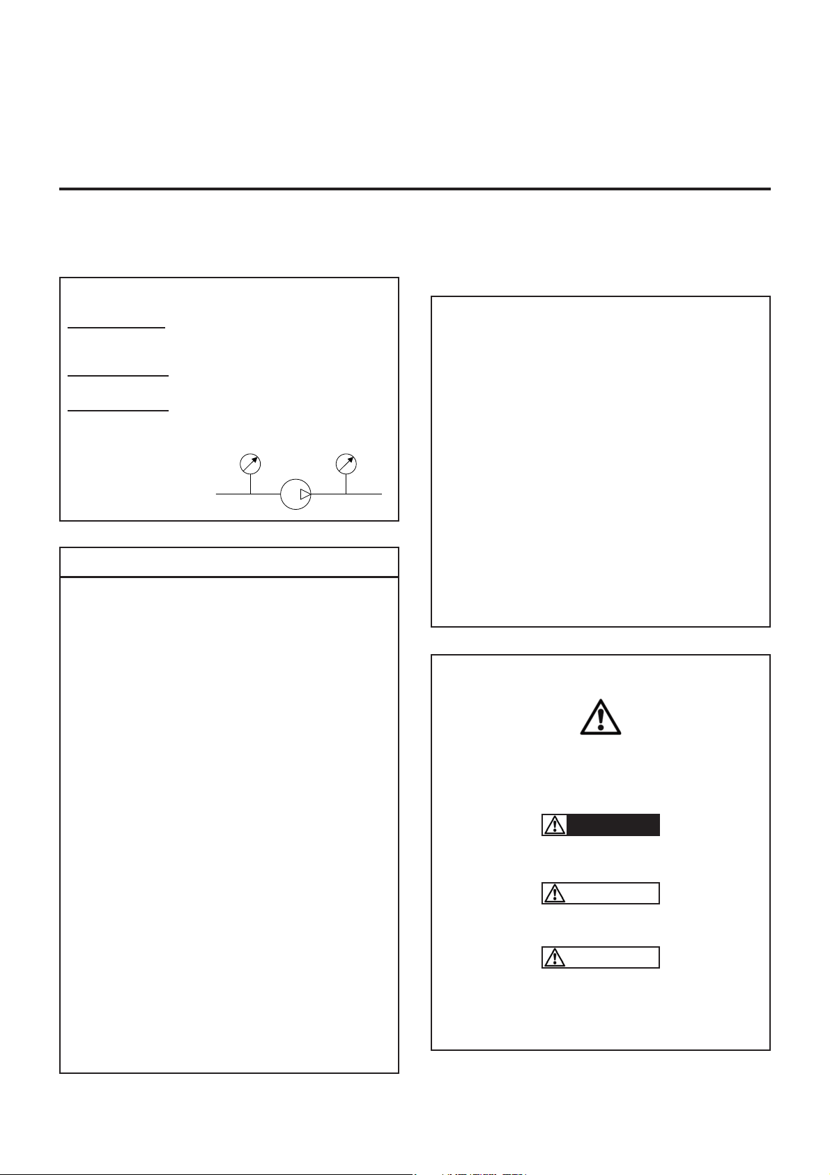
USED PRESSURE UNITS
Unit without suffix :
Differential pressure, for example, pressure difference between
equipment suction and discharge.
Unit with suffix
"a" :
Absolute pressure.
Unit with suffix
"g" :
Gauge pressure, given regarding to atmospheric pressure
(~101325 Pa, taken at 1 bar / 14,5 psi in this IOM).
P
P
f
Psuc
Pdis
Pump
Example :
Psuc = -0,2 barg = 0,8 bara
Pdis = 8,8 barg = 9,8 bara
∆P = Pdis - Psuc = 9 bar
Definition of safety symbols
This is a SAFETY ALERT SYMBOL.
When you see this symbol on the product, or in the manual,
look for one of the following signal words and be alert to the
potential for personal injury, death or major property damage.
Warns of hazards that WILL cause serious personal injury,
death or major property damage.
Warns of hazards that CAN cause serious personal injury,
death or major property damage.
Warns of hazards that CAN cause personal injury or property
damage.
NOTICE
Indicates special instructions which are very important and
must be followed.
DANGER
WARNING
CAUTION
asp
Pompe
re
3/15
NT 1002-B00 07 19 S4C Pump e
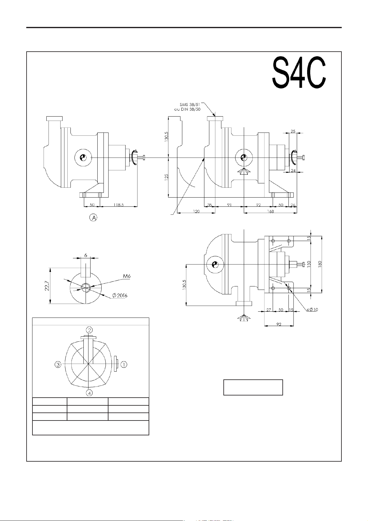
1. OVERALL DIMENSIONS
Pump plate
POSITION OF THE ORIFICES
Dimensions in millimetres
Weight : 23,5 kg
Orifices Connection Standards
Suction 1 - 2 - 3 - 4 1
Discharge 1 - 2 - 3 - 4 2
This position of the mounting bracket does not permit
orientation of the discharge in position 4.
4/15
NT 1002-B00 07 19 S4C Pump e
2.1 Installation design
2.1.1 Pump
To obtain the service expected from a MOUVEX pump,
regarding both performance and longevity, it is vital that
the type of pump, its speed and the materials used for its
construction are determined as a function of the pump
output, its installation and operating conditions.
You can contact our Technical Services at any time to
ask for the information you require.
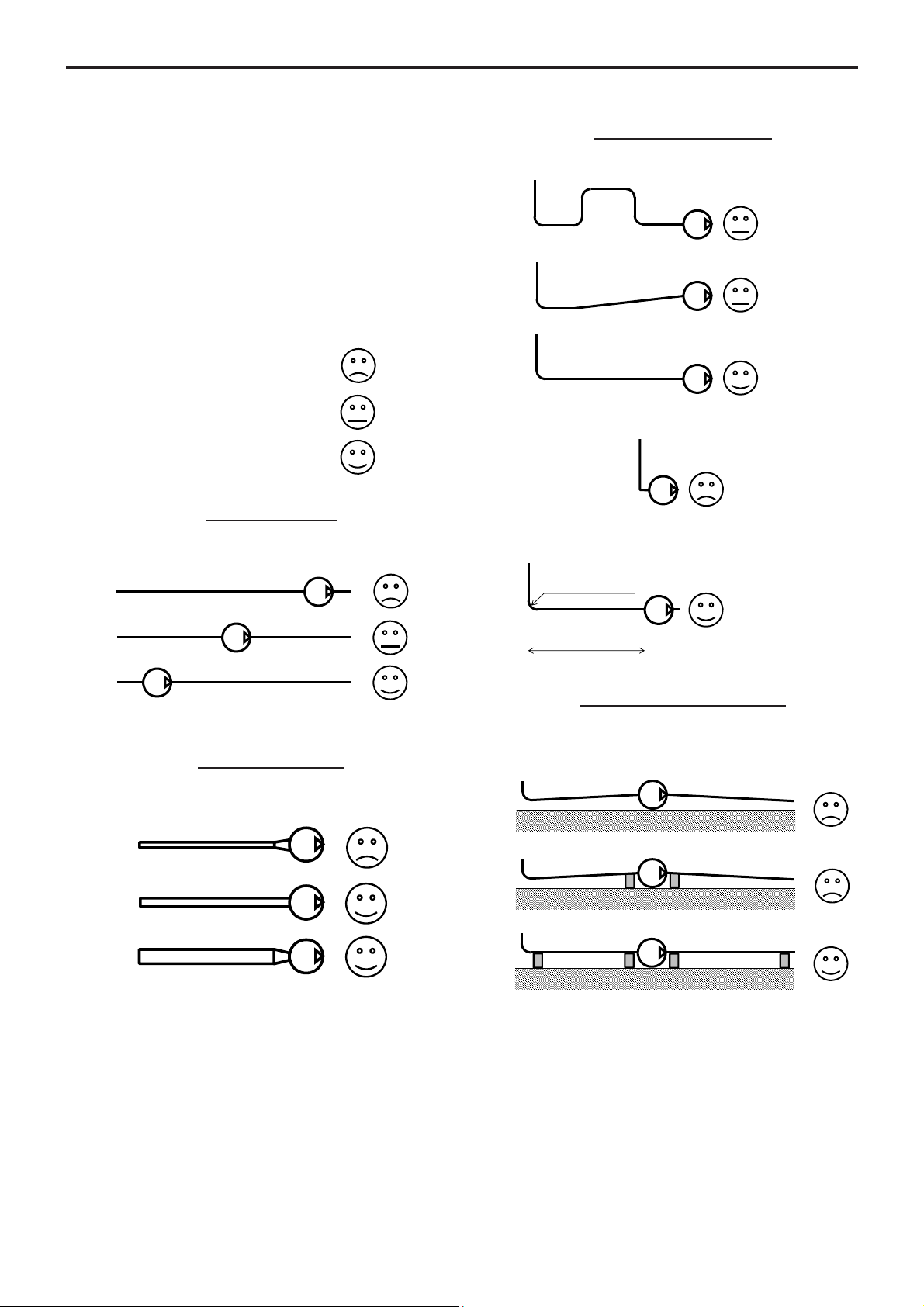
2.1.2 Pipe
Suction pipe length
Length should be as short as possible.
Suction pipe diameter
Diameter must be at least equal to pump port diameter
and even more if required by pumping conditions.
Suction pipe configuration
Check tightness to avoid accidental air intake.
--------------------------------------------------------------------
Pipe alignment and supporting
Pump must not support piping nor endure stress resulting from piping weight or dilatation effects. For latters,
expansion loops should be included.
Not recommended
To be avoided if possible
Recommended
2. INSTALLATION
R=3xDminimum
L=10xDminimum
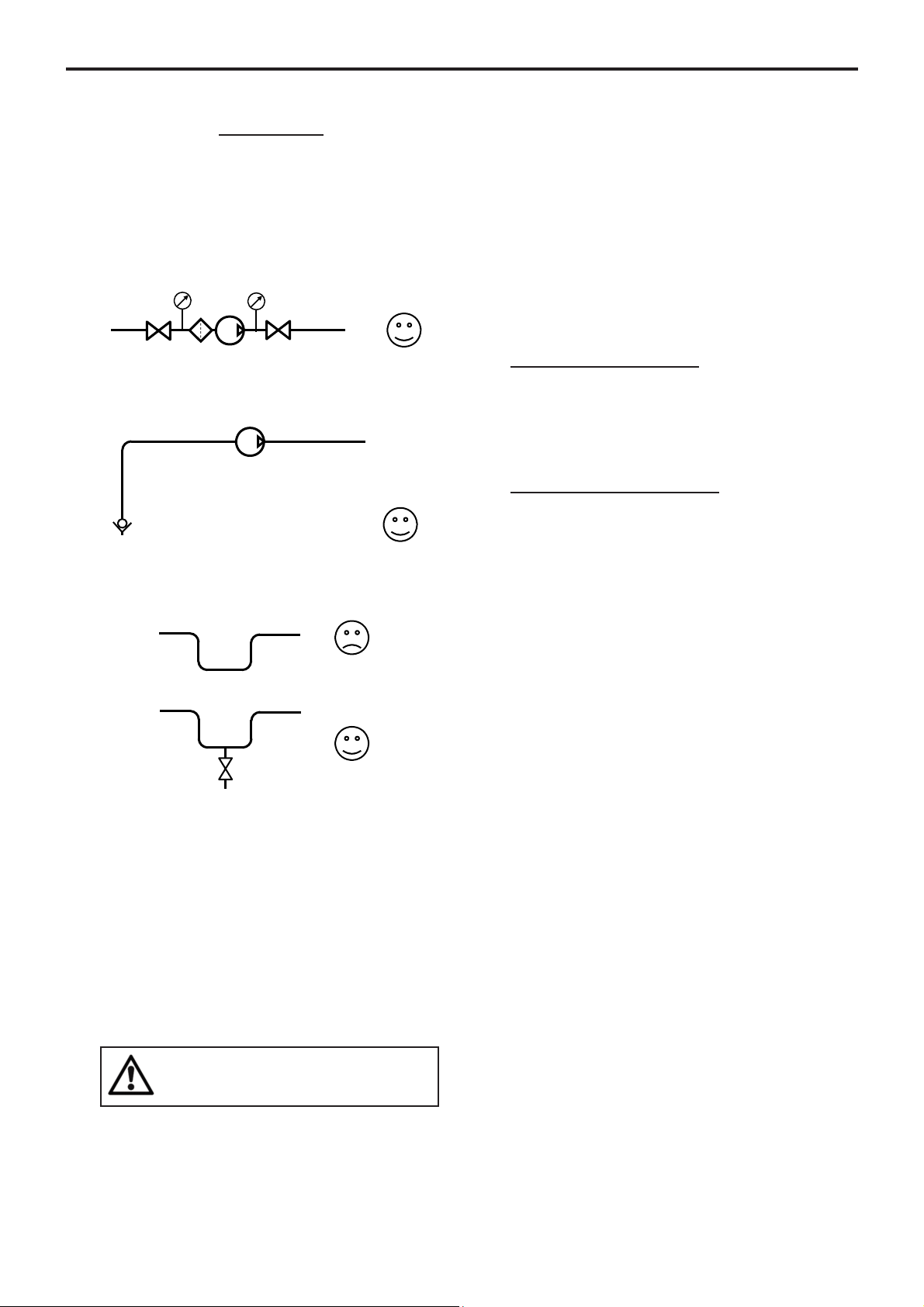
Pipe equipment
• Place valves close to the pump to avoid draining pipe
during maintenance operations. Preferably select full
bore ball or butterfly valves.
Pressure connections on pump suction and discharge
are recommended for settings and controls.
Make sure piping, vessels valves and other installation
devices are carefully cleaned before mounting.
• MOUVEX pumps are self priming. However, if line
emptying should be avoided and/or if suction lift is high,
a foot valve can be added.
• If pumped liquid presents a risk of in pipe solidification
and potential dilatation, low points on the pipe should
be avoided or equipped with drain valve.
• If installation is heated, it must be designed so that fluid
dilatation can evacuate through piping. Therefore fluid
contained in piping must be heated before fluid contained
in the pump. Also check that a heated pump is not isolated by closed valves.
The S Series pump is a selfpriming volumetric PD pump.
Therefore, the pump must not run on a circuit with a closed
valve. This is valid both for the suction circuit and for the
discharge circuit.
For hoses fitting on pump suction or discharge, a hose
whip restrain device must be installed to limit the whip or
travel of the pressurized hose at start up, or in case the
hose breaks free.
2.2 Orientation of the pump ports
The suction port and the discharge port may be oriented
in various positions (see overall dimensions plan).
If the port positions need to be changed at the time of
installation, see the corresponding §.
The suction port may be oriented the top, the right or the
left. Unless otherwise specified, the equipment is delivered with the suction port the right (for an observer facing
the back of the pump).
The discharge port may be oriented at any angle around
the pump's horizontal axis.
To orient the suction port
(cf. § DISMANTLING THE PUMP) :
Unscrew the 4 screws 002 at the back of the pump
mounting braket 001. Orient the pumps’ suction port
101 to the desired position. Screw back the 4 screws
002 at the back of the pump mounting braket 001.
To orient the discharge port :
Unscrew the 4 nuts 106 then remove the base 401.
Orient the base 401 to the desired position. Tighten the
nuts 106.
2.3 Direction of rotation
The S4C pump only has one rotation direction (the pump
not being reversible), clockwise (observer facing the
back of the pump).
When connecting the motor, make sure, by observing the
shaft, that the motor is turning in the correct direction.
An incorrect rotation direction will not damage the pump
but it will not allow the unit to pump product.
WARNING: SEVERE PERSONAL INJURY OR
PROPERTY DAMAGE CAN CAUSE FROM
WHIPPING HOSES.
2. INSTALLATION (continued)
5/15
NT 1002-B00 07 19 S4C Pump e
 Loading...