

Mouvex HYDRIVE 2010A, HYDRIVE 2020A Instructions Manual
HYDRIVE 2010A - 2020A
INSTRUCTIONS 206-A00 e
Section 206
Effective October 2011
Replaces March 2011
INSTALLATION
OPERATION
MAINTENANCE
SAFETY
STORAGE
Original instructions
Your distributor :
Z.I. La Plaine des Isles - F 89000 AUXERRE - FRANCE
Tel. : +33 (0)3.86.49.86.30 - Fax : +33 (0)3.86.49.87.17
contact@mouvex.com - www.mouvex.com
2/16
NT 206-A00 10.11 Hydrive e
1. OVERALL DIMENSIONS . . . . . . . . . . . . . . . . . . . . . . . . . .3
2. TECHNICAL DATA . . . . . . . . . . . . . . . . . . . . . . . . . . . . . . .4
3. INSTALLATION . . . . . . . . . . . . . . . . . . . . . . . . . . . . . . . . .4
3.1 Hydraulic circuits . . . . . . . . . . . . . . . . . . . . . . . . . . . . . .4
3.2 Mounting the HYDRIVE . . . . . . . . . . . . . . . . . . . . . . . .6
3.3 Hydraulic oil . . . . . . . . . . . . . . . . . . . . . . . . . . . . . . . . .9
3.4 Priming the system . . . . . . . . . . . . . . . . . . . . . . . . . . . .9
3.5 Engaging Hydraulic Motor . . . . . . . . . . . . . . . . . . . . .10
3.6 Adjusting the relief valve . . . . . . . . . . . . . . . . . . . . . . .10
3.7 Setting HYDRIVE fan speed . . . . . . . . . . . . . . . . . . . .11
4. OPERATION . . . . . . . . . . . . . . . . . . . . . . . . . . . . . . . . . .12
4.1 HYDRIVE pre-start up check list . . . . . . . . . . . . . . . .12
4.2 HYDRIVE operation . . . . . . . . . . . . . . . . . . . . . . . . . .12
5. MAINTENANCE . . . . . . . . . . . . . . . . . . . . . . . . . . . . . . . .13
5.1 Maintenance schedule . . . . . . . . . . . . . . . . . . . . . . . .13
5.2 Return filter replacement . . . . . . . . . . . . . . . . . . . . . .13
5.3 Fan replacement . . . . . . . . . . . . . . . . . . . . . . . . . . . . .13
6. TROUBLESHOOTING . . . . . . . . . . . . . . . . . . . . . . . . . . .14
7. STORAGE CONDITIONS . . . . . . . . . . . . . . . . . . . . . . . . .15
8. SCRAPPING . . . . . . . . . . . . . . . . . . . . . . . . . . . . . . . . . .15
9. CERTIFICATE OF CONFORMITY . . . . . . . . . . . . . . . . . .16
TABLE OF CONTENTS Page
HYDRAULICS COOLERS
SAFETY, STORAGE, INSTALLATION, OPERATION AND MAINTENANCE INSTRUCTIONS
MODELS : HYDRIVE 2010A & 2020A
Cooler N° :
Date of bringing into service :
NOTE :
Numbers in parentheses following individual parts indicate
reference numbers on the corresponding Parts Lists.
NOTICE :
The HYDRIVE MUST only be installed in systems which have been
designed by qualified engineering personnel. The system MUST
conform to all applicable local and national regulations and safety
standards.
This manual is intended to assist in the installation and operation of
the HYDRIVE and MUST be kept with the HYDRIVE.
HYDRIVE service shall be performed by qualified technicians ONLY.
Service shall conform to all applicable local and national regulations
and safety standards.
Thoroughly review this manual, all instructions and hazard warnings,
BEFORE performing any work on the HYDRIVE
Gloves shall be worn when handling sheet metal to avoid any risk of
injury.
Maintain ALL system and HYDRIVE operation and hazard warning
decals.
This is a SAFETY ALERT SYMBOL
When you see this symbol on the product, or in the manual, look
for one of the following signal words and be alert to the potential for
personal injury, death or major property damage.
Warns of hazards that WILL cause serious personal injury,
death or major property damage
Warns of hazards that CAN cause serious personal injury,
death or major property damage.
Warns of hazards that CAN cause personal injury or property
damage.
NOTICE
Indicates special instructions which are very important and
must be followed.
SAFETY INFORMATIONS
WARNING
CAUTION
DANGER
3/16
NT 206-A00 10.11 Hydrive e
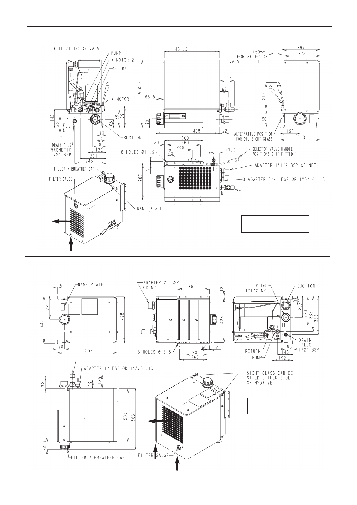
1. OVERALL DIMENSIONS
HYDRIVE 2010
HYDRIVE 2020
DISCHARGE
SUCTION
DISCHARGE
SUCTION
REVOLVING T 1”1/16 JIC M/F/M
REVOLVING T 1”5/16 JIC M/F/M
4/16
NT 206-A00 10.11 Hydrive e
2. TECHNICAL DATA
3. INSTALLATION
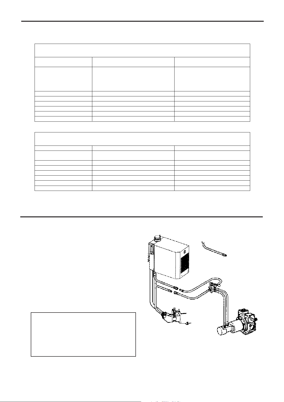
3.1 Hydraulic circuits
Figure 1 shows the hydraulic circuit for a single motor
drive system (without selector valve). If driving a motor
in both directions, install a directional control valve in the
circuit as shown (figure1).
The HYDRIVE is NOT suitable for use for systems using
tipping rams (hydraulic cylinders).
NOTE
Use bulkhead fittings to prevent any overstressing of the
hoses and connections between the tractor and trailer.
Figure 1
System layout without selector valve
HYDRIVE
PTO
Pump
Hydraulic
pump
Non-spill couplings
Directional
control valve
“T” connector
fitting
NOTICE :
The HYDRIVE must only be installed in systems designed by qualified engineering personnel. System design must conform with all
applicable regulations and codes and must
provide warning of all system hazards.
HYDRIVE 2010A
Oil Flow Rate
Circuit pressure
2 possible versions :
170 bar
270 bar
Maximum pressure allowed
Fan speed 2800 rpm 2800 rpm
Return pressure 15 - 75 PSI 1 - 5 bar
Heat Dissipation 13.5 HP for 70°F temperature rise 10 kw for 40 °C Temperature rise
Fan Motor Flow 1.5 U.S GPM 5.5 l / min
Weight (Dry) 53 lbs 24 kg
Oil Tank Capacity 2.5 US Gallons 10 liters
15 - 32 US GPM 55 - 120 l / min
RV set @ :
2465 PSI
5639 PSI
3983 PSI
RV set @ :
170 bar
270 bar
280 bar
HYDRIVE 2020A
Oil Flow Rate 15 - 50 US GPM 55 - 190 l / min
Circuit pressure
Maximum pressure allowed
Fan speed 2800 rpm 2800 rpm
Return pressure 15 - 75 PSI 1 - 5 bar
Heat Dissipation 26 HP for 70°F temperature rise 20 kw for 40 °C Temperature rise
Fan Motor Flow 2.2 U.S GPM 8.2 l / min
Weight (Dry) 77 lbs 35 kg
Oil Tank Capacity 4.5 US Gallons 17 liters
RV set @ 3675 PSI
4978 PSI
RV set @ 253 bar
350 bar
5/16
NT 206-A00 10.11 Hydrive e
3. INSTALLATION (continued)
There are 2 versions of the HYDRIVE 2010, standard version
and selector valve version. (NOTE : Use a remote on / off
valve on hydraulic systems using the hydrive 2010 without
the selector valve).
The selector version features a manually operated spool
valve so that the high pressure oil (from the hydraulic pump)
can be switched between two possible hydraulic motors
(Motor 1 & Motor 2). The valve can also be set to neutral position with the system unloaded, and the oil returning back to
the tank.
The selector version is designed for tanker applications
where both a compressor and pump may be installed on a
vehicle but operated separately. HYDRIVES are NOT suitable for use with hydraulic cylinders.
The selector valve is NOT available for the HYDRIVE 2020
model.
The HYDRIVE 2010 is not designed for use with 2 motors
running simultaneously unless the system is designed to
allow multi motor operation.
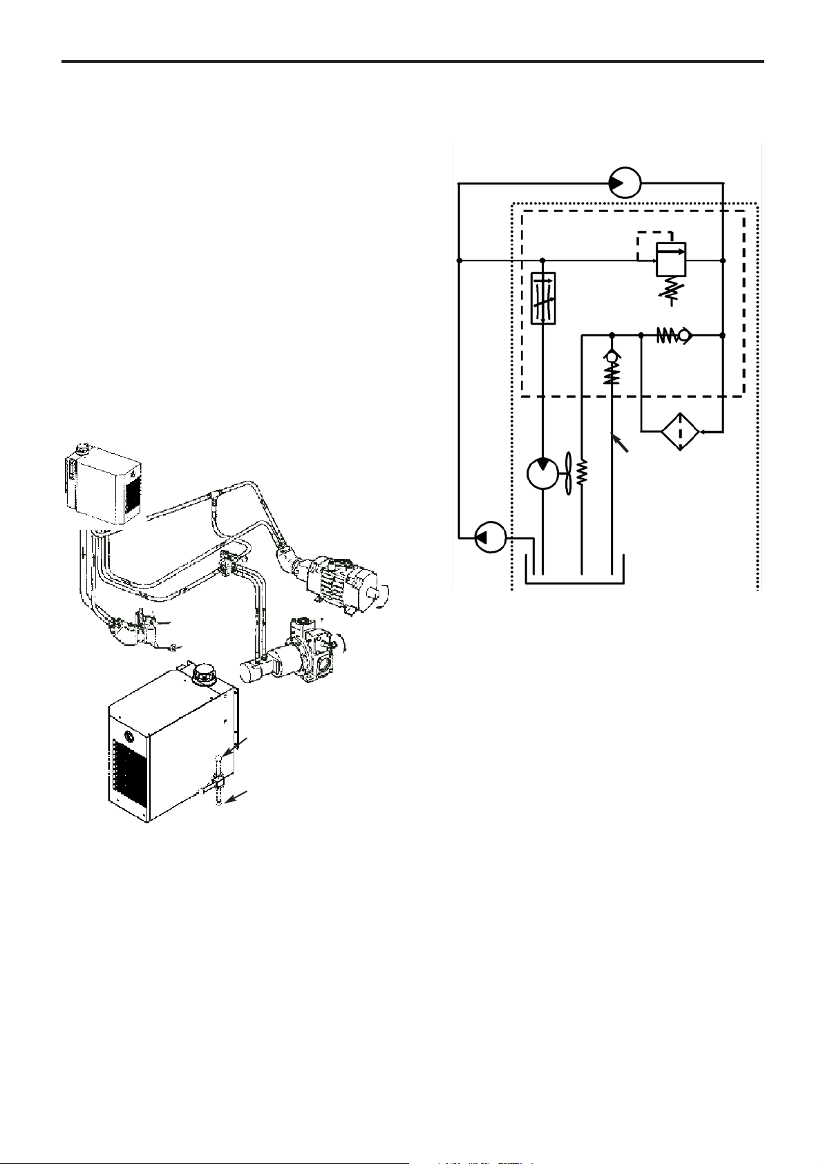
3.1.1 STANDARD HYDRIVE 2010A & 2020A
HYDRAULIC CIRCUIT
1. Adjustable relief valve
2. Fan speed control valve
3. Return line filter
4. Fan motor
5. Filter by-pass valve
6. Oil cooler radiator
7. Fan
8. System pressure gauge point
(not accessible for the 2010)
9. Return pressure gauge point
NOTES
THE DRIVEN MACHINE, PUMP OR COMPRESSOR, WILL START AUTOMATICALLY WHEN THE HYDRAULIC PUMP IS ENGAGED UNLESS A
REMOTE ON/OFF CONTROL VALVE IS INSTALLED IN THE SYSTEM.
A cold start bypass protects the cooler and quickly warms the
oil to its normal working temperature.
Direction
valve
Compressor
(Motor 1)
Pompe (Motor 2)
Figure 2
HYDRIVE 2010 with selector valve
Motor 1
Motor 2
HYDRIVE
Hydraulic
pump
Oil tank
Suction
line
High pressure line
1
3
4
5
6
7
8
9
Hydraulic
pump
Return line
Cold start
bypass
Valve block
 Loading...