

Mouvex C24 i, C36 i Maintance Manual
C24 i - C36 i
PUMPS
INSTALLATION
OPERATION
MAINTENANCE
INSTRUCTIONS 1001-C00 e
Section 1001
Effective November 2008
Replaces March 2008
Original instructions
Your distributor :
Z.I. La Plaine des Isles - F 89000 AUXERRE - FRANCE
Tel. : +33 (0)3.86.49.86.30 - Fax : +33 (0)3.86.49.87.17
contact@mouvex.com - www.mouvex.com

2/21
NT 1001-C00 11.08 C24 i - C36 i e
ECCENTRIC PISTON PUMP
MOUVEX PRINCIPLE
SAFETY INSTRUCTIONS, STORAGE, INSTALLATION AND MAINTENANCE
C24 i - C36 i MODELS
Pump N° :
Commissioning date :
TECHNICAL CHARACTERISTICS
- Maximum pump speed : 460 rpm
- Maximum running temperature :
• PTFE L seals . . . . . . . . . . . . . . . . . . . . . . . . . . 80°C
• other seals :
* continuous . . . . . . . . . . . . . . . . . . . . . . . . . .100°C
* washing/rinsing/sterilisation . . . . . . . . . . . . .121°C
- Maximum suction pressure :
• In normal use, the suction pressure must be higher than the
required NPSH and less than 2 bar (29 psi).
• During CIP/SIP of the pump, the suction pressure must not
exceed 3 bar (43,5 psi).
• Pump stopped, the pressure must not exceed 6 bar (87 psi).
- Maximum differential pressure :
• C24 i . . . . . . .9 bar (130,5 psi)*
• C36 i . . . . . . .6 bar (87 psi)*
- Cylinder capacity :
• C24 i . . . . . . .0,946 litre
• C36 i . . . . . . .1,420 litre
- Informations about PTFE L seals :
• This seal is composed of fibreglass.
• CAUTION : This seal does not accept thermal shock
and Clean In Place.
* When the pump works with an inlet pressure less than zero, the maximum
outlet pressure will be calculated as if the inlet pressure is equal to zero.
1. OVERALL DIMENSIONS . . . . . . . . . . . . . . . . . . . . . . . . . .3
2. INSTALLATION . . . . . . . . . . . . . . . . . . . . . . . . . . . . . . . . .7
2.1 Orientation of the pump ports . . . . . . . . . . . . . . . . . . . .7
2.2 Direction of rotation . . . . . . . . . . . . . . . . . . . . . . . . . . . .7
2.3 Protection of the pump installation . . . . . . . . . . . . . . . .7
2.4 Hoisting devices . . . . . . . . . . . . . . . . . . . . . . . . . . . . . .8
2.5 Unit Assembly . . . . . . . . . . . . . . . . . . . . . . . . . . . . . . . .8
3. UTILISATION . . . . . . . . . . . . . . . . . . . . . . . . . . . . . . . . .10
3.1 Noise level . . . . . . . . . . . . . . . . . . . . . . . . . . . . . . . . .10
3.2 Commissioning . . . . . . . . . . . . . . . . . . . . . . . . . . . . . .10
3.3 Dry running . . . . . . . . . . . . . . . . . . . . . . . . . . . . . . . . .10
3.4 Pump stop . . . . . . . . . . . . . . . . . . . . . . . . . . . . . . . . . .10
4. CLEAN IN PLACE (CIP) & STERILISATION IN
PLACE (SIP) . . . . . . . . . . . . . . . . . . . . . . . . . . . . . . . . . .11
4.1 General . . . . . . . . . . . . . . . . . . . . . . . . . . . . . . . . . . . .11
4.2 CIP circuit recommended . . . . . . . . . . . . . . . . . . . . . .11
4.3 Pumps arranged in series . . . . . . . . . . . . . . . . . . . . . .11
4.4 Pumps arranged in parallel . . . . . . . . . . . . . . . . . . . . .12
4.5 Successive cycles . . . . . . . . . . . . . . . . . . . . . . . . . . . .13
4.6 Sterilisation In Place (SIP) . . . . . . . . . . . . . . . . . . . . .13
5. MAINTENANCE . . . . . . . . . . . . . . . . . . . . . . . . . . . . . . . .13
5.1 Necessary tools . . . . . . . . . . . . . . . . . . . . . . . . . . . . .13
6. OPENING OF THE PUMP . . . . . . . . . . . . . . . . . . . . . . . .14
6.1 Assembly / Dismantling . . . . . . . . . . . . . . . . . . . . . . . .14
6.2 Checking of parts . . . . . . . . . . . . . . . . . . . . . . . . . . . .15
7. ASSEMBLY OF CYLINDER/PISTON . . . . . . . . . . . . . . . .16
8. PROTECTION OF THE BELLOWS . . . . . . . . . . . . . . . . . .17
9. CHANGING THE LIP SEAL . . . . . . . . . . . . . . . . . . . . . . .18
10. CHANGING THE ORIENTATION OF THE PORTS . . . . .19
10.1 Discharge port . . . . . . . . . . . . . . . . . . . . . . . . . . . . . .19
10.2 Suction port . . . . . . . . . . . . . . . . . . . . . . . . . . . . . . . .19
11. DRAINING OF BEARING . . . . . . . . . . . . . . . . . . . . . . . .20
12. OPTIONS . . . . . . . . . . . . . . . . . . . . . . . . . . . . . . . . . . .21
12.1 Liquid detector . . . . . . . . . . . . . . . . . . . . . . . . . . . . .21
12.2 Bellows monitoring system . . . . . . . . . . . . . . . . . . . .21
SUMMARY Page
This is a SAFETY ALERT SYMBOL
When you see this symbol on the product, or in the manual, look
for one of the following signal words and be alert to the potential for
personal injury, death or major property damage.
Warns of hazards that WILL cause serious personal injury,
death or major property damage
Warns of hazards that CAN cause serious personal injury,
death or major property damage.
Warns of hazards that CAN cause personal injury or property
damage.
NOTICE
Indicates special instructions which are very important and
must be followed.
SAFETY INFORMATIONS
WARNING
CAUTION
DANGER
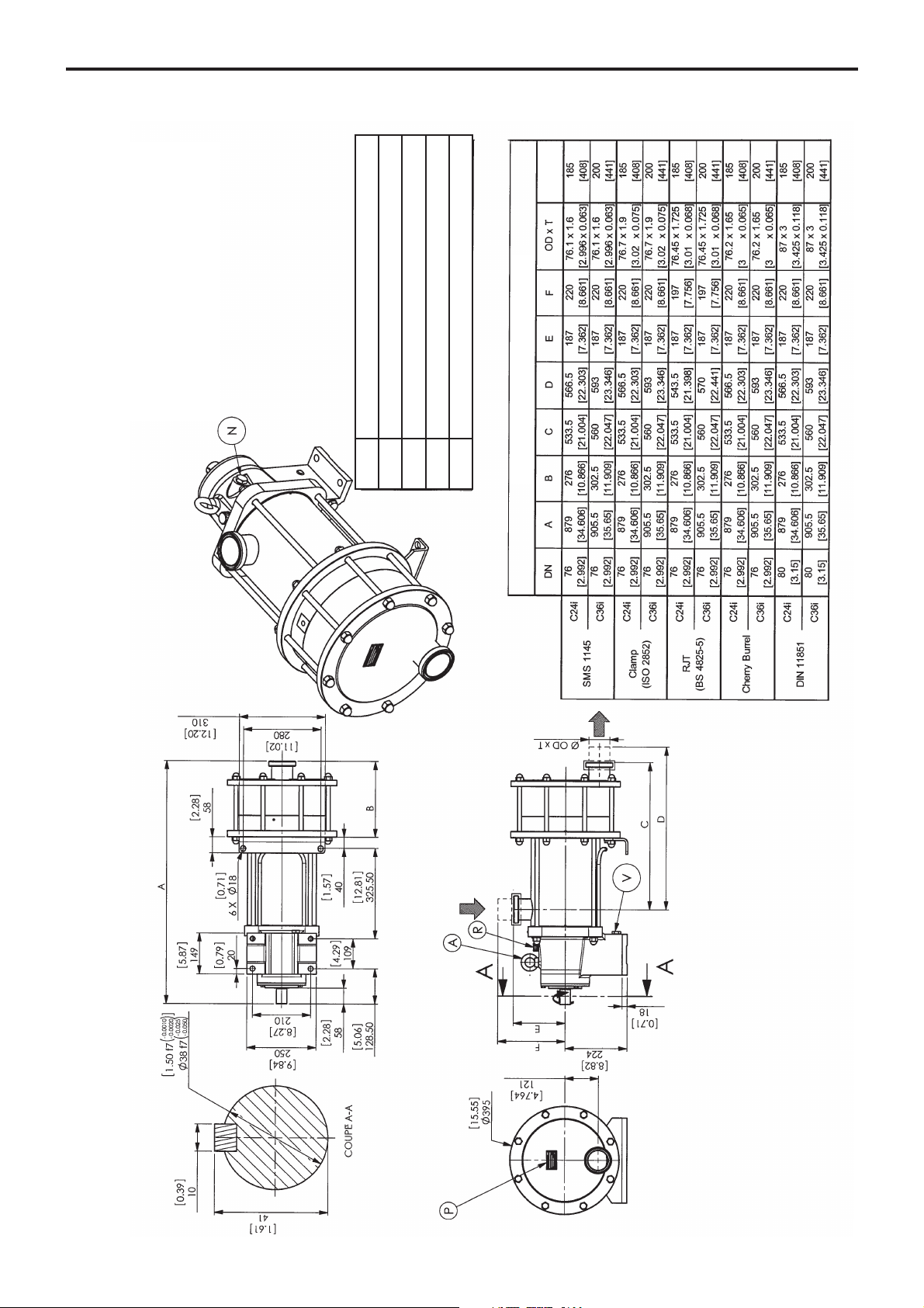
1. OVERALL DIMENSIONS
NT 1001-C00 11.08 C24 i - C36 i e
3/21
C24 i - C36 i
with connections
Lifting ring
Pump plate
Filling / Breather
Draining
Oil level
A
P
R
V
N
Weight
Connections
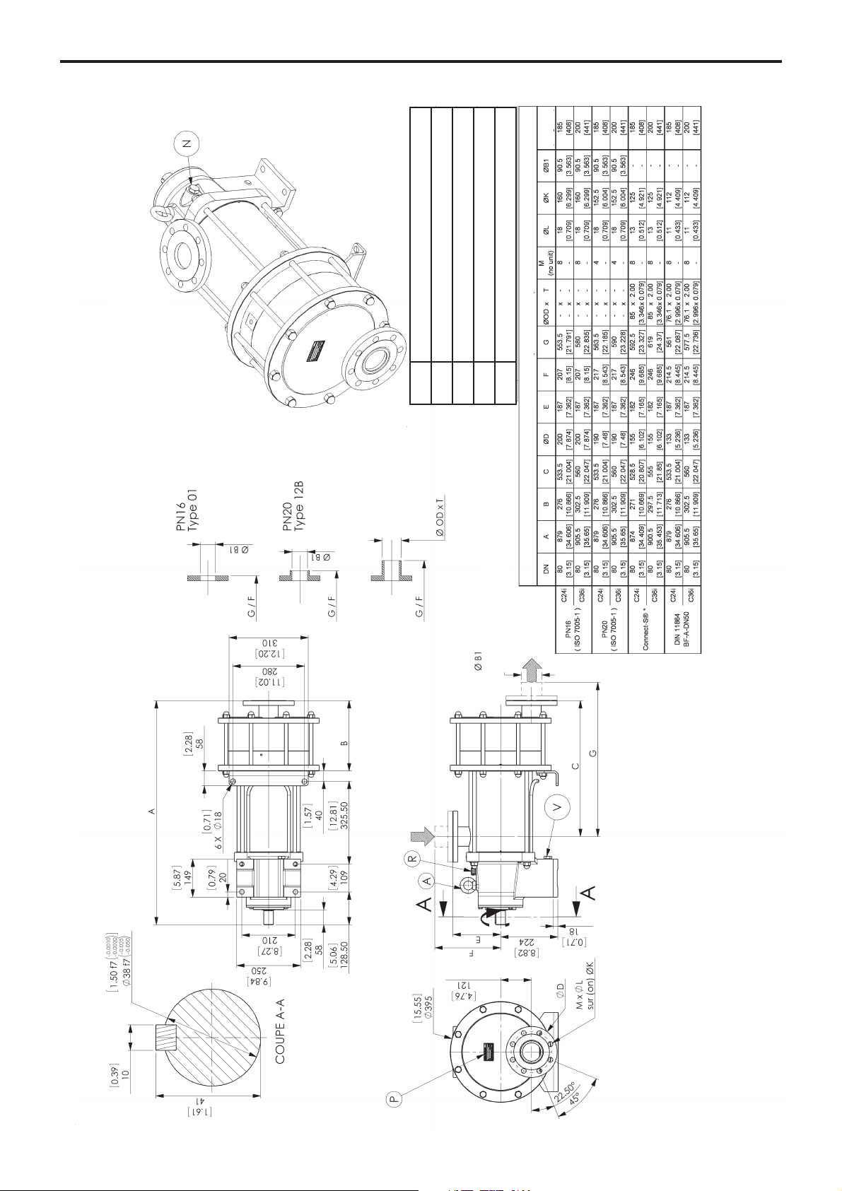
1. OVERALL DIMENSIONS (continued)
4/21
NT 1001-C00 11.08 C24 i - C36 i e
Lifting ring
Pump plate
Filling / Breather
Draining
Oil level
A
P
R
V
N
C24 i - C36 i
Flanges
Shrinked on and
welded pipe
Shrinked on and
welded pipe
Others
Butt welded piping
Companion flange drilling
Connect S-
®
is a registered trademark owned by NEUMO.
Weight

1. OVERALL DIMENSIONS (continued)
5/21
NT 1001-C00 11.08 C24 i - C36 i e
NOTE :
For the other sides, see the specific overall dimension plan for the connection.
Maximum jacket pressure : 8 bar (116 psi)
Maximum jacket temperature : FKM and FEP encapsulated FKM seals : 180°C.
JACKET CONNECTION 1" B.S.P.F
The entry connection may be connected to one or two points.
STEAMLIQUID
The outlet connection may be connected to one or two points.
If it is done at 1 point, purge the air at the second point.
CAUTION :
The pumped product must not exceed the maximum temperature of the pump.
FOR ATEX PUMPS, SEE INSTRUCTIONS NR 1050.
C24 : 867.50 - C36 : 900
8 (plug)
C24 i - C36 i
with heating jacket

1. OVERALL DIMENSIONS (continued)
6/21
NT 1001-C00 11.08 C24 i - C36 i e
Bellows monitoring system
C24 - C36
NOTA :
Setting of detecion levels is done in factory and do not have to be modified.
For other dimensions, report to pump dimensional drawing.
The dismantling of the transmission could be done only in factory.
CAUTION :
A BAD CONNECTION CAN DESTROY THE SENSOR.
Wiring diagramm
Connector
Do not use S2
Normal operation
Leakage detection

7/21
NT 1001-C00 11.08 C24 i - C36 i e
The C Series pump is a selfpriming volumetric PD pump.
Therefore, the pump must not run on a circuit with a closed
valve. This is valid both for the suction circuit and for the
discharge circuit.
2.1 ORIENTATION OF THE PUMP PORTS
The suction and discharge ports may be oriented in
various positions.
If the ports positions needs to be changed at any time,
see the corresponding paragraph.
2.2 DIRECTION OF ROTATION
An arrow situated on the bearing housing indicates the
correct direction of rotation.
When looking at the shaft, the rotation will be clockwise.
When looking at the front cover, the direction of rotation
will be anti-clockwise.
Verification of the correct rotation direction : Turn the
pump the wrong way is not dangerous for the pump.
2.3 PROTECTION OF THE PUMP INSTALLATION
• For ease of maintenance, it is a good idea to place isolation valves before and after the pump. The sizing of
these valves must correspond to the diameter of the
pipes.
• Before any start-up, during operation or complete stopping of the pump, make sure the valves are open
.
• During stop periods, with the pump full of product,
either the suction or discharge circuit must be left open
to enable expansion or contraction of the pumped product through reheating or cooling. If this instruction is
not complied with, The bellows may be damaged and
lead to premate failure.
• The bearing must be ventilate at all times, therefore the
breather mounted on the bearing must be re-used.
Never put the bung on
.
• In case of flodded suction, it is possible to install a liquid
detector in the place of the transmission breather (see
§ OPTIONS). This detector will enable the user to be
informed in the case of failure of the bellows. In the
case of detection, the installer must make sure the
pump is stopped and the isolating valves are closed.
Non compliance with this instruction can lead to the
pumped product being spilt outside the pump.
• It is possible to have a puncture detection system with
double-walled bellows : an inert gas is maintained under
pressure between the 2 walls and said pressure is permanently monitored. A signal is dispatched immediately
should a wall become punctured (see § OPTIONS).
• The stop time may lead to cooling of the product in the
pump and therefore to an increase in viscosity. If this is
the case, we recommend re-starting the pump at a
speed adapted to this new viscosity (starting pump).
Once the product arrives in the pump at the installation
definition temperature, the pump may run at the speed
specified for this application.
NOTICE
C-Series pumps remains drainable whatever
position is chosen for the inlet port, but the
outlet port must be at the bottom (position 4)
to keep the self-draining capability.
2. INSTALLATION
POSSIBLE POSITIONS
SUCTION
DISCHARGE
 Loading...