

Mouvex C12 A, C18 A Maintance Manual
C12 A - C18 A
PUMPS
INSTALLATION
OPERATION
MAINTENANCE
INSTRUCTIONS 1001-F00 e
Section 1001
Effective October 2010
Replaces August 2010
Original instructions
Your distributor :
Z.I. La Plaine des Isles - F 89000 AUXERRE - FRANCE
Tel. : +33 (0)3.86.49.86.30 - Fax : +33 (0)3.86.49.87.17
contact@mouvex.com - www.mouvex.com
2/20
NT 1001-F00 10.10 C12 A - C18 A e
TECHNICAL CHARACTERISTICS
- Maximum pump speed : 530 rpm
- Maximum running temperature : 100°C
- Maximum suction pressure :
• In normal use, the suction pressure must be higher than the
required NPSH and less than 1,5 barg (21,75 psig).
• Pump stopped, the pressure must not exceed 6 barg
(87 psig).
- Acceptable maximal differential pressure :
• C12 A...........................9 bar (130,5 psi)*
• C18 A...........................6 bar (87 psi)*
- Maximum pressure jacket : 8 barg (116 psig)
- Cylinder capacity :
• C12 A ...........................0,411 litre
• C18 A ...........................0,617 litre
* When the pump works with an inlet gauge pressure less than zero, the
maximum outlet pressure will be calculated as if the inlet pressure is
equal to zero.
1. OVERALL DIMENSIONS . . . . . . . . . . . . . . . . . . . . . . . . . .3
2. INSTALLATION . . . . . . . . . . . . . . . . . . . . . . . . . . . . . . . . .6
2.1 Orientation of the pump ports . . . . . . . . . . . . . . . . . . . .6
2.2 Direction of rotation . . . . . . . . . . . . . . . . . . . . . . . . . . . .6
2.3 Protection of the pump installation . . . . . . . . . . . . . . . .6
2.4 Hoisting devices . . . . . . . . . . . . . . . . . . . . . . . . . . . . . .7
2.5 Unit Assembly . . . . . . . . . . . . . . . . . . . . . . . . . . . . . . . .7
3. UTILISATION . . . . . . . . . . . . . . . . . . . . . . . . . . . . . . . . . .9
3.1 Noise level . . . . . . . . . . . . . . . . . . . . . . . . . . . . . . . . . .9
3.2 Commissioning . . . . . . . . . . . . . . . . . . . . . . . . . . . . . . .9
3.3 Dry running . . . . . . . . . . . . . . . . . . . . . . . . . . . . . . . . . .9
3.4 Pump stop . . . . . . . . . . . . . . . . . . . . . . . . . . . . . . . . . .10
3.5 Scrapping . . . . . . . . . . . . . . . . . . . . . . . . . . . . . . . . . .10
4. MAINTENANCE . . . . . . . . . . . . . . . . . . . . . . . . . . . . . . . .10
4.1 Necessary tools . . . . . . . . . . . . . . . . . . . . . . . . . . . . .10
5. OPENING OF THE PUMP . . . . . . . . . . . . . . . . . . . . . . . .10
5.1 Assembly / Dismantling . . . . . . . . . . . . . . . . . . . . . . . .11
5.2 Checking of parts . . . . . . . . . . . . . . . . . . . . . . . . . . . .12
6. REASSEMBLY OF CYLINDER/PISTON . . . . . . . . . . . . . .13
7. PROTECTION OF THE BELLOWS . . . . . . . . . . . . . . . . . .14
8. CHANGING THE LIP SEALS . . . . . . . . . . . . . . . . . . . . . .15
9. CHANGING THE ORIENTATION OF THE DISCHARGE
PORT . . . . . . . . . . . . . . . . . . . . . . . . . . . . . . . . . . . . . . .15
10. BYPASS . . . . . . . . . . . . . . . . . . . . . . . . . . . . . . . . . . . .16
10.1 Bypass adjustment . . . . . . . . . . . . . . . . . . . . . . . . . .16
10.2 Changing the spring . . . . . . . . . . . . . . . . . . . . . . . . .16
10.3 Replacement of the seals . . . . . . . . . . . . . . . . . . . . .16
11. HEATING JACKET (OPTION) . . . . . . . . . . . . . . . . . . . .17
11.1 Replacement of the jacket seal . . . . . . . . . . . . . . . . .17
11.2 Bleed (included with jacket option) . . . . . . . . . . . . . .17
12. DRAINING OF BEARING . . . . . . . . . . . . . . . . . . . . . . . .18
13. OPTIONS . . . . . . . . . . . . . . . . . . . . . . . . . . . . . . . . . . .19
13.1 Liquid detector . . . . . . . . . . . . . . . . . . . . . . . . . . . . .19
13.2 Bellow monitoring system . . . . . . . . . . . . . . . . . . . . .19
14. CERTIFICATE OF CONFORMITY . . . . . . . . . . . . . . . . .20
TABLE OF CONTENTS Page
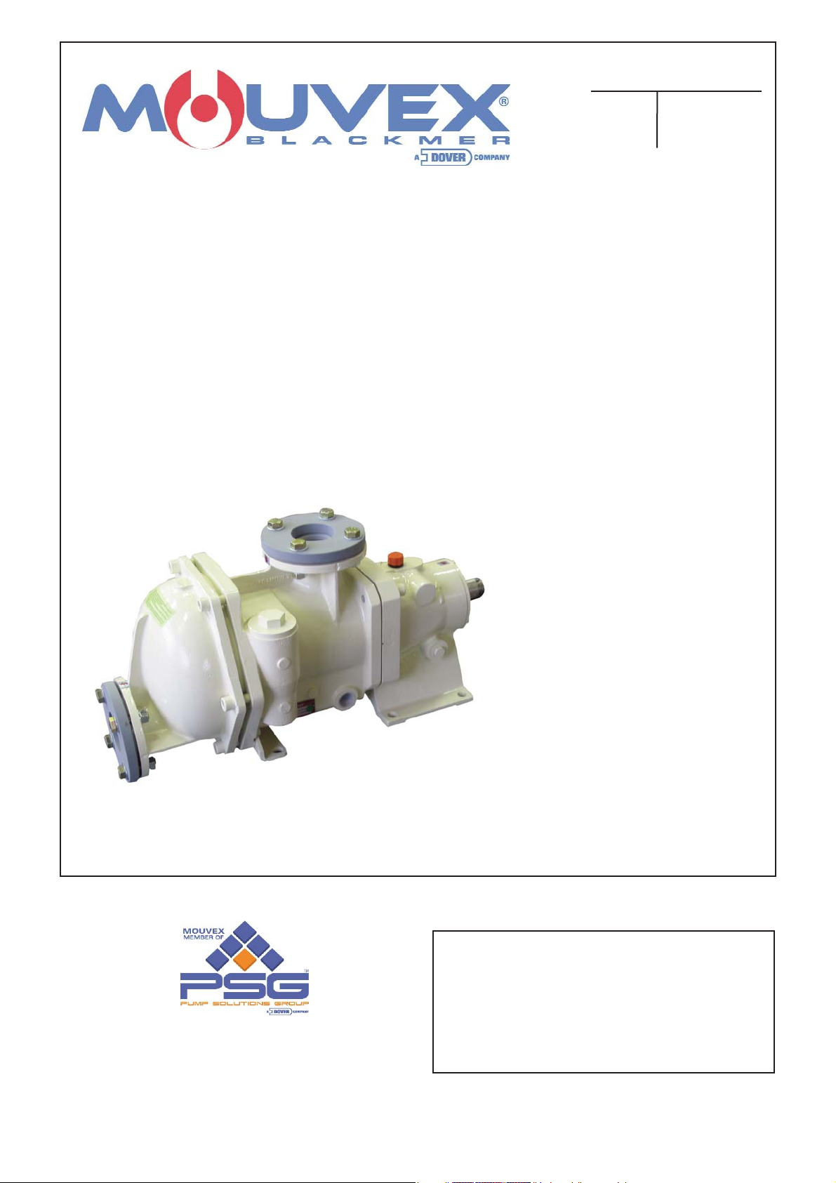
ECCENTRIC PISTON PUMP
MOUVEX PRINCIPLE
SAFETY INSTRUCTIONS, STORAGE, INSTALLATION AND MAINTENANCE
MODELS : C12 A - C18 A
This is a SAFETY ALERT SYMBOL
When you see this symbol on the product, or in the manual, look
for one of the following signal words and be alert to the potential for
personal injury, death or major property damage.
Warns of hazards that WILL cause serious personal injury,
death or major property damage
Warns of hazards that CAN cause serious personal injury,
death or major property damage.
Warns of hazards that CAN cause personal injury or property
damage.
NOTICE
Indicates special instructions which are very important and
must be followed.
SAFETY INFORMATIONS
WARNING
CAUTION
DANGER
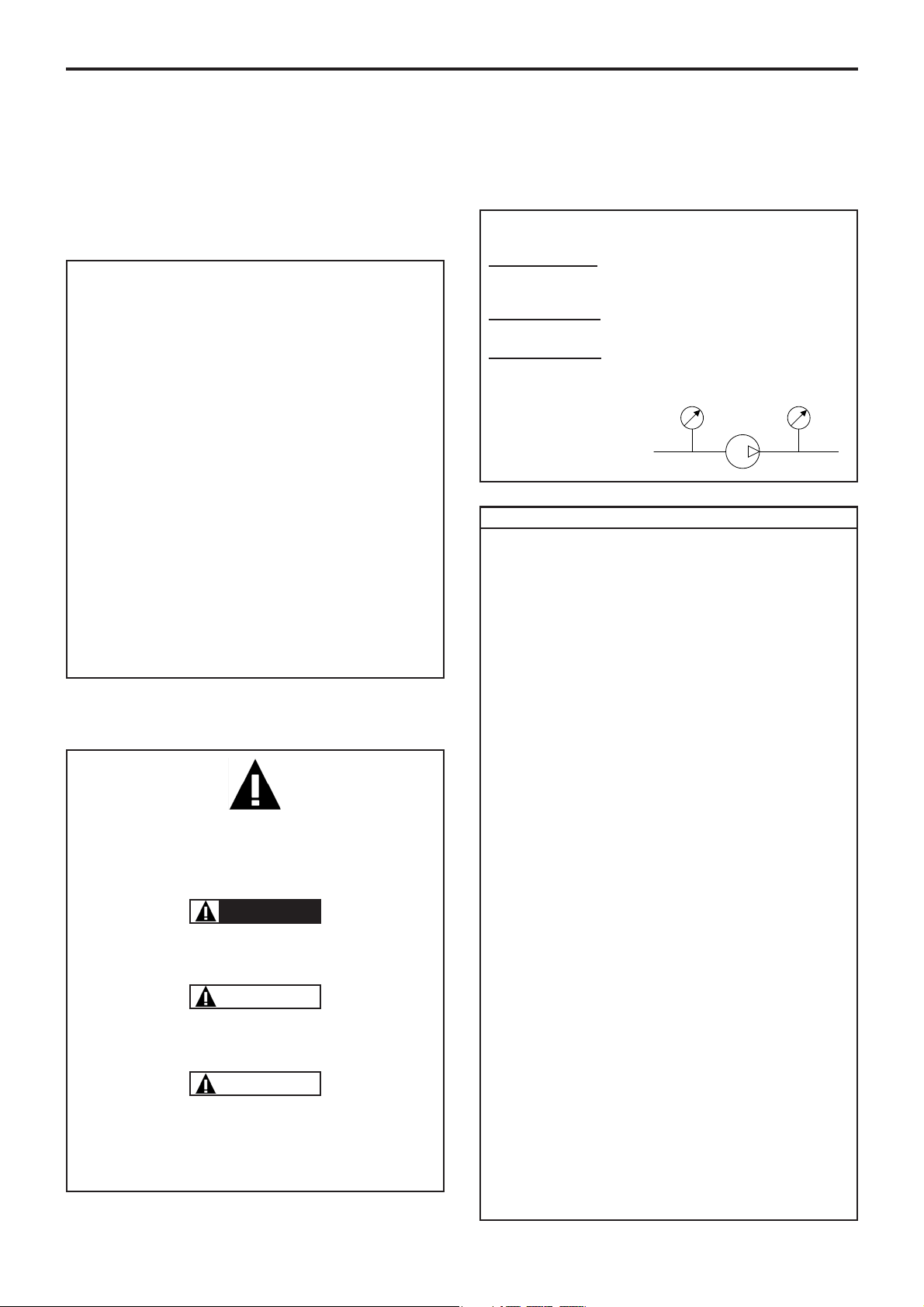
USED PRESSURE UNITS
Unit without suffix :
Differential pressure, for example, pressure difference between
equipment suction and discharge.
Unit with suffix
"a" :
Absolute pressure.
Unit with suffix
"g" :
Gauge pressure, given regarding to atmospheric pressure
(~101325 Pa, taken at 1 bar / 14,5 psi in this IOM).
P
P
f
Psuc
Pdis
Pump
Example :
Psuc = -0,2 barg = 0,8 bara
Pdis = 8,8 barg = 9,8 bara
∆P = Pdis - Psuc = 9 bar
asp
Pompe
re
3/20
NT 1001-F00 10.10 C12 A - C18 A e
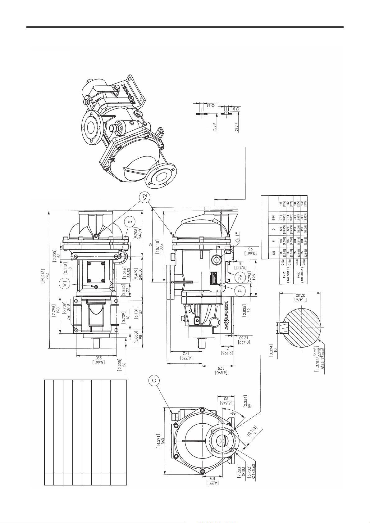
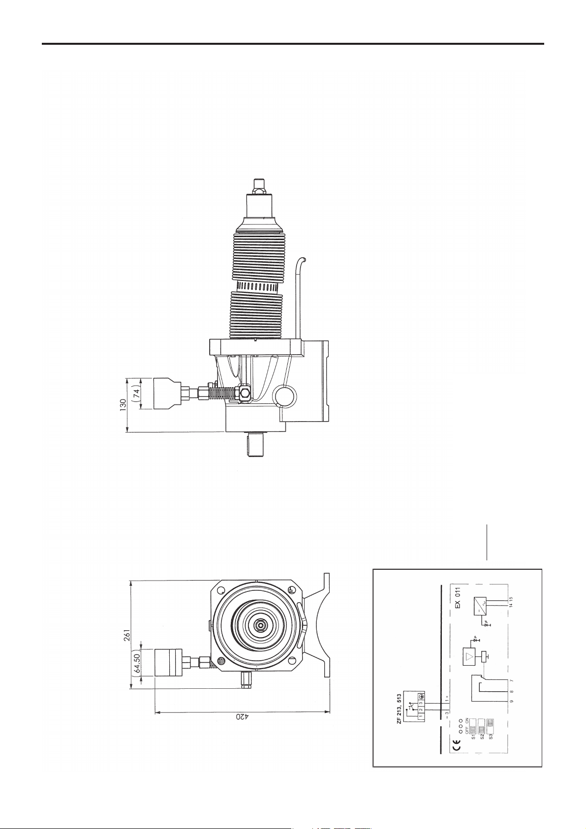
1. OVERALL DIMENSIONS
C12 A - C18 A
Ø B1
Companion flange drilling
Flanges
Bypass valve
Pump plate
Filling / Breather
Draining of transmission
Draining of main body 1/4" BSP (option)
Draining of front cover 1/4" BSP (option)
Jacket (variant)
Mounting point for probe :
M6 - threaded width : max. 8 mm.
C
P
R
V
V1
V2
EV
S
4 equidistant ablong holes
Weight
kg [lb]
PN16
Type 01
Shrinked on
and welded pipe
PN20
Type 12B
Shrinked on
and welded pipe
4/20
NT 1001-F00 10.10 C12 A - C18 A e
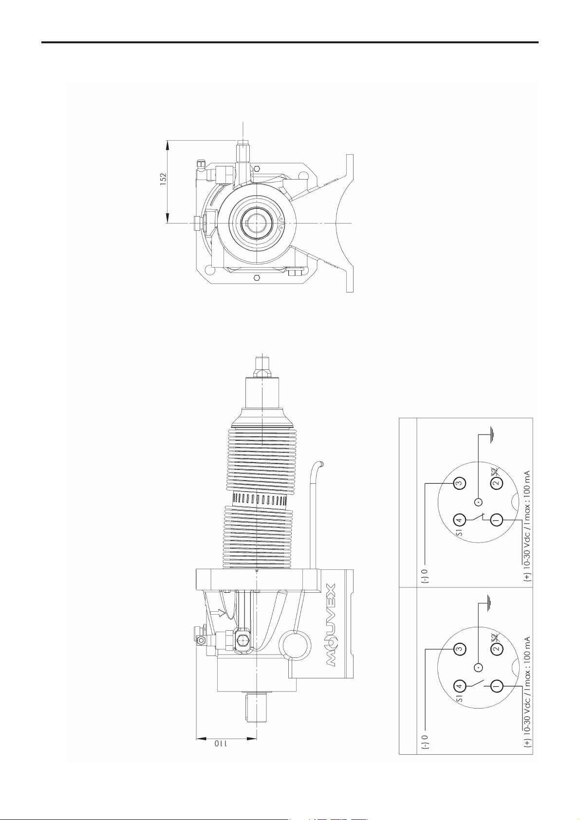
1. OVERALL DIMENSIONS (continued)
Bellows monitoring system
C12 - C18
Leakage detection
NOTA :
Setting of detecion levels is done in factory and do not have to be modified.
For other dimensions, report to pump dimensional drawing.
The dismantling of the transmission could be done only in factory.
Wiring diagramm
Connector
Do not use S2
Normal operation
CAUTION :
A BAD CONNECTION CAN
DESTROY THE SENSOR.
5/20
NT 1001-F00 10.10 C12 A - C18 A e
1. OVERALL DIMENSIONS (continued)
Bellows monitoring system ATEX
C12 - C18
NOTA :
Setting of detecion levels is done in factory and do not have to be modified.
For other dimensions, report to pump dimensional drawing.
The dismantling of the transmission could be done only in factory.
With falling pressure 3-2 opens.
CAUTION
:
Incorrect connection can lead to :
- a flammability risk,
- ineffective monitoring,
- possible damage to the sensor.
Connection diagram
Ex-free Zone
Ex-Zone 1 or 2, 21 or 22
Supply voltage
Output
Yellow
Green
Microswitch
6/20
NT 1001-F00 10.10 C12 A - C18 A e
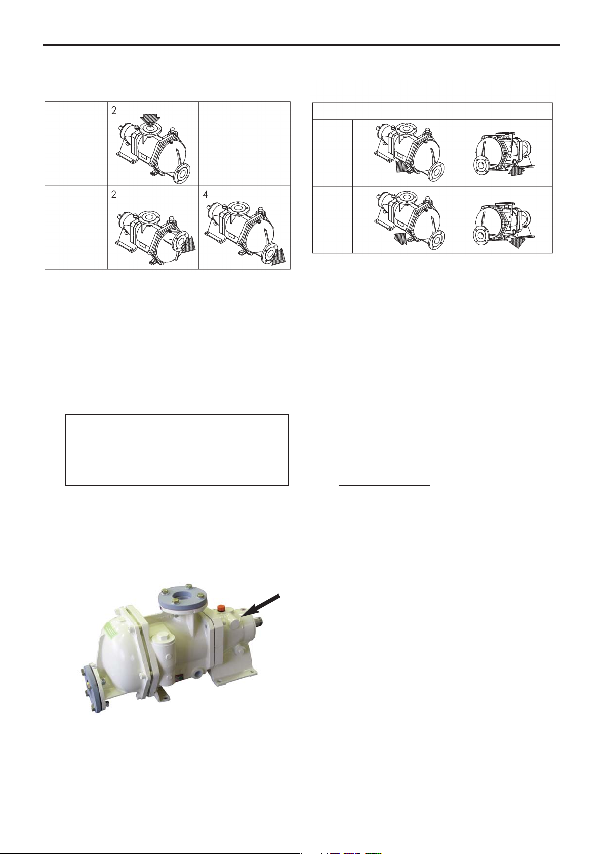
2. INSTALLATION
POSSIBLE POSITIONS
JACKET CONNECTION (variant)
1" CYLINDER GAS
LIQUID
STEAM
SUCTION
DISCHARGE
STANDARD
STANDARD
The C Series pump is a selfpriming volumetric PD pump.
Therefore, the pump must not run on a circuit with a closed
valve. This is valid both for the suction circuit and for the discharge circuit.
2.1 Orientation of the pump ports
The discharge port may be oriented in various positions.
If the port positions needs to be changed at any time,
see the corresponding paragraph.
2.2 Direction of rotation
When looking at the shaft, the rotation will be clockwise.
When looking at the front cover, the direction of rotation
will be anti-clockwise. An arrow situated on the bearing
housing indicates the correct direction of rotation.
Verification of the correct rotation direction :
Turn the pump the wrong way is not dangerous for the
pump.
2.3 Protection of the pump installation
• For ease of maintenance, it is a good idea to place isolation valves before and after the pump. The sizing of
these valves must correspond to the diameter of the
pipes.
• Before any start-up, during operation or complete stopping of the pump, make sure the valves are open.
• During stop periods, with the pump full of product,
either the suction or discharge circuit must be left open
to enable expansion or contraction of the pumped product through reheating or cooling. If this instruction is
not complied with, The bellows may be damaged and
lead to premate failure.
• The bearing must be ventilate at all times, therefore the
breather mounted on the bearing must be re-used.
Never put the bung on
.
• In case of flodded suction, it is possible to install a
liquid detector in the place of the transmission breather
(see § options). This detector will enable the user to be
informed in the case of failure of the bellows. In the
case of detection, the installer must make sure the
pump is stopped and the isolating valves are closed.
Non compliance with this instruction can lead to the
pumped product being spilt outside the pump.
• It is possible to have a puncture detection system with
double-walled bellows : an inert gas is maintained under
pressure between the 2 walls and said pressure is permanently monitored. A signal is dispatched immediately
should a wall become punctured (see § OPTIONS).
• The stop time may lead to cooling of the product in the
pump and therefore to an increase in viscosity. If this is
the case, we recommend re-starting the pump at a
speed adapted to this new viscosity (starting pump).
Once the product arrives in the pump at the installation
definition temperature, the pump may run at the speed
specified for this application.
NOTICE
C-Series pumps remains drainable whatever
position is chosen for the inlet port, but the
outlet port must be at the bottom (position 4)
to keep the self-draining capability.
 Loading...