

Mouvex AK, AK O, AK I Maintance Manual
AK PUMPS
Constructions O - I
INSTALLATION
OPERATION
MAINTENANCE
INSTRUCTIONS 1003-E00 e
Section 1003
Effective September 2012
Replaces September 2011
Original instructions
Your distributor :
Z.I. La Plaine des Isles - F 89000 AUXERRE - FRANCE
Tel. : +33 (0)3.86.49.86.30 - Fax : +33 (0)3.86.49.87.17
contact@mouvex.com - www.mouvex.com
2/19NT 1003-E00 09.12 AK O - AK I e
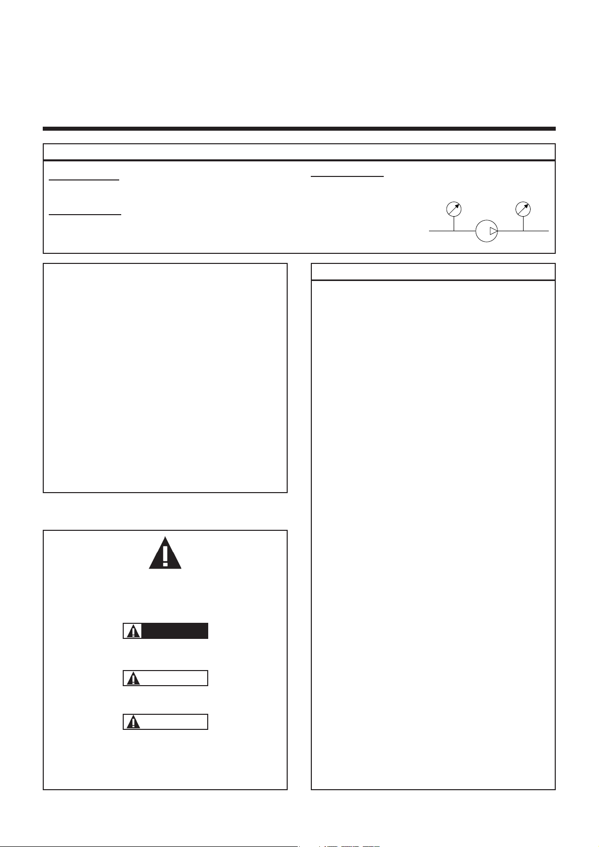
This is a SAFETY ALERT SYMBOL
When you see this symbol on the product, or in the manual, look
for one of the following signal words and be alert to the potential for
personal injury, death or major property damage.
Warns of hazards that WILL cause serious personal injury,
death or major property damage
Warns of hazards that CAN cause serious personal injury,
death or major property damage.
Warns of hazards that CAN cause personal injury or property
damage.
NOTICE
Indicates special instructions which are very important and
must be followed.
SAFETY INFORMATIONS
WARNING
CAUTION
DANGER
ECCENTRIC PISTON PUMP
MOUVEX PRINCIPLE
SAFETY, STORAGE, INSTALLATION AND MAINTENANCE INSTRUCTIONS
MODELS : AK O - AK I
TECHNICAL CHARACTERISTICS
• Constructions :
O : Cast iron and steel
i : Ni-resist iron, Kanigen coated iron and stainless
steel
• Maximum suction pressure : less than 1 barg
• Acceptable maximal differential pressure :
* Construction O : 5 bar
* Construction I : 3,5 bar
• Maximum pressure jacket : 8 barg
• Maximum pump speed : 520 rpm
• Maximum operating temperature :
* 150°C with FKM seals
• Cylinder capacity : 0,399 litre
TABLE OF CONTENTS Page
1. OVERALL DIMENSIONS . . . . . . . . . . . . . . . . . . . . . . . . . .3
2. INSTALLATION . . . . . . . . . . . . . . . . . . . . . . . . . . . . . . . . .4
2.1 Choice of pump . . . . . . . . . . . . . . . . . . . . . . . . . . . . . . .4
2.2 Piping diameters . . . . . . . . . . . . . . . . . . . . . . . . . . . . . .4
2.3 Piping assembly . . . . . . . . . . . . . . . . . . . . . . . . . . . . . .4
2.4 Direction of rotation . . . . . . . . . . . . . . . . . . . . . . . . . . . .4
2.5 Single bypass . . . . . . . . . . . . . . . . . . . . . . . . . . . . . . . .5
2.6 Double bypass . . . . . . . . . . . . . . . . . . . . . . . . . . . . . . .5
2.7 Cleaning . . . . . . . . . . . . . . . . . . . . . . . . . . . . . . . . . . . .5
2.8 Anchoring the pump units . . . . . . . . . . . . . . . . . . . . . . .5
2.9 Alignment of motor / pump and reduction gearbox /
pump shafts . . . . . . . . . . . . . . . . . . . . . . . . . . . . . . . . .5
2.10 Electric motors . . . . . . . . . . . . . . . . . . . . . . . . . . . . . .6
2.11 Diesel engine drive . . . . . . . . . . . . . . . . . . . . . . . . . . .6
3. USE . . . . . . . . . . . . . . . . . . . . . . . . . . . . . . . . . . . . . . . . . .7
3.1 Storage . . . . . . . . . . . . . . . . . . . . . . . . . . . . . . . . . . . . .7
3.2 Pumping hot products . . . . . . . . . . . . . . . . . . . . . . . . . .7
3.3 Pump with heating jacket . . . . . . . . . . . . . . . . . . . . . . .7
3.4 Pump filled with product at shutdown . . . . . . . . . . . . . .7
3.5 Starting-up the pump . . . . . . . . . . . . . . . . . . . . . . . . . .7
3.6 Shutting down the pump . . . . . . . . . . . . . . . . . . . . . . . .7
3.7 Scrapping . . . . . . . . . . . . . . . . . . . . . . . . . . . . . . . . . . .7
4. OPENING THE PUMP TO INSPECT THE CYLINDER/
PISTON AND BUSHINGS . . . . . . . . . . . . . . . . . . . . . . . . .8
4.1 Necessary tools . . . . . . . . . . . . . . . . . . . . . . . . . . . . . .9
4.2 Removing the front cover . . . . . . . . . . . . . . . . . . . . . . .9
4.3 Removing the piston and cylinder . . . . . . . . . . . . . . . .9
4.4 Assembly of the cylinder, piston and front cover . . . . .9
5. MECHANICAL SEALS . . . . . . . . . . . . . . . . . . . . . . . . . . .10
5.1 Operation . . . . . . . . . . . . . . . . . . . . . . . . . . . . . . . . . .10
5.2 Dismantling . . . . . . . . . . . . . . . . . . . . . . . . . . . . . . . . .10
5.3 Assembly . . . . . . . . . . . . . . . . . . . . . . . . . . . . . . . . . . .11
6. BYPASS . . . . . . . . . . . . . . . . . . . . . . . . . . . . . . . . . . . . .12
6.1 Operation . . . . . . . . . . . . . . . . . . . . . . . . . . . . . . . . . .12
6.2 Orientation . . . . . . . . . . . . . . . . . . . . . . . . . . . . . . . . .12
6.3 Inversion . . . . . . . . . . . . . . . . . . . . . . . . . . . . . . . . . . .13
6.4 Adjustment . . . . . . . . . . . . . . . . . . . . . . . . . . . . . . . . .13
6.5 Obtaining the flow . . . . . . . . . . . . . . . . . . . . . . . . . . . .14
6.6 Energy consumption . . . . . . . . . . . . . . . . . . . . . . . . . .14
7. MAINTENANCE . . . . . . . . . . . . . . . . . . . . . . . . . . . . . . . .14
7.1 Greasing . . . . . . . . . . . . . . . . . . . . . . . . . . . . . . . . . . .14
7.2 Checking of parts . . . . . . . . . . . . . . . . . . . . . . . . . . . .14
8. DRILLED PISTON PUMP . . . . . . . . . . . . . . . . . . . . . . . . .15
9. PUMP WITH JACKET . . . . . . . . . . . . . . . . . . . . . . . . . . .15
10. TROUBLESHOOTING . . . . . . . . . . . . . . . . . . . . . . . . . .16
11. CERTIFICATE OF CONFORMITY . . . . . . . . . . . . . . . . .19
Unit without suffix :
Differential pressure, for example, pressure difference between
equipment suction and discharge.
Unit with suffix
"a" :
Absolute pressure.
Unit with suffix
"g" :
Gauge pressure, given regarding to atmospheric pressure
(~101325 Pa, taken at 1 bar / 14,5 psi in this IOM).
P
P
f
Psuc
Pdis
Pump
Example :
Psuc = -0,2 barg = 0,8 bara
Pdis = 8,8 barg = 9,8 bara
∆P = Pdis - Psuc = 9 bar
USED PRESSURE UNITS
asp
Pompe
re
3/19NT 1003-E00 09.12 AK O - AK I e
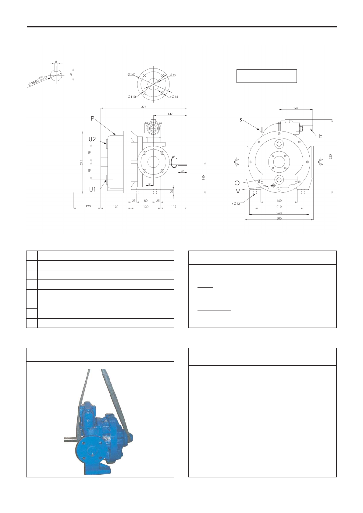
1. OVERALL DIMENSIONS
Weight : 41 kg
I
Noise level
The sound level of a pump is greatly influenced by its conditions of use. Cavitation and pumping products with high gas
contents generally increases the sound level.
Under the following pumping conditions :
• excluding cavitation
• discharge pressure : 5 bar
• speed of rotation 520 rpm
• product viscosity of 1 cSt
The sound level reached for the AK pump in good conditions
(ignoring the motor and gearbox noise) is less than 80 dB(A).
Lifting points
E
Bypass valve.
I
Space required for removing front cover.
O
Draining port for heating jacket 2 threaded holes G1” B.S.P.
P
Pump plate.
S
Mounting point for probe : M6 - threaded width : max. 8 mm.
U1
Inlet/outlet depending of heating fluid
2 threaded holes G1/2" B.S.P.
U2
V
Pump drain G1/4” B.S.P.
Connection of heating jacket
Heating fluid :
Steam
:
• Inlet ................ U2
• Outlet .............. U1
Heating liquid
:
• Inlet ................ U1
• Outlet .............. U2
4/19NT 1003-E00 09.12 AK O - AK I e
2. INSTALLATION
2.1 Choice of pump
To obtain the service expected from a MOUVEX pump,
regarding both performance and longevity, it is vital that
the type of pump, its speed and the materials used for its
construction are determined as a function of the pump
output, its installation and operating conditions.
You can contact our Technical Services at any time to
ask for the information you require.
2.2 Piping diameters
The location of the pump in the transfer or recycling circuit
should always be determined so as to reduce the suction
height and length of the piping as much as possible.
The diameter of the pipes must be determined as a function of their length on the one hand, and the flow and viscosity of the product on the other, so that head loss
remains within design limits. Therefore it is difficult to
give general and precise directions.
However, we recall that it is never prejudicial to plan for
wide piping diameters, particularly regarding the intake.
For the discharge, it is also possible to plan for a diameter equal to that of the pump's orifices, and on the intake, for a wider diameter if suction is very strong. In the
case of viscous products, the determination of this diameter is very important since the variation of head loss
is proportional to the viscosity and inversely proportional
to the power of 4th of the diameter. Therefore a small
reduction of piping diameter can have major consequences. Our Technical Services are always available to provide you with precise data if you give them accurate
information or, better still, the installation plans.
2.3 Piping assembly
Wherever possible, siphons and reverse slopes in the
suction piping must be avoided and all the gaskets must
be installed with great care to avoid air from entering the
piping.
The elbows must always have a large radius and must
not be assembled too close to the pump flanges, at the
inlet as well as the outlet side.
A straight pipe 5 diameters is recommended between
the pump flange and any pipe fitting (elbow, valve…).
The stresses exerted by the piping on the pump can
deform the pump parts, increase wear, misalign the bearings and even cause parts to break.
The pipes must be designed to allow thermal expansion
and contraction and be firmly secured (the use of flexible hoses and expansion loops is recommended).
We recommend placing isolating valves close to the
pump flanges to permit dismantling and replacement
without having to drain the installation. These valves
should have the same diameter as the pipes and, by
preference, be a full bore model.
A strainer should be fitted in the suction line to prevent
the introduction of foreign bodies into the pump.
Before installing the new piping and tanks, clean them
carefully to remove welding waste, rust, etc., which
when carried by the liquid may damage the pump.
If the liquid may freeze or solidify, prepare for draining
the piping by installing drain taps at the low points and
air vents at the high points.
In the case of a very high intake or if you wish to prevent
the piping from emptying at shutdown, you can install a
foot valve. It should have a large diameter so as not to
generate additional head loss.
Connection of heating jacket :
See § OVERALL DIMENSIONS.
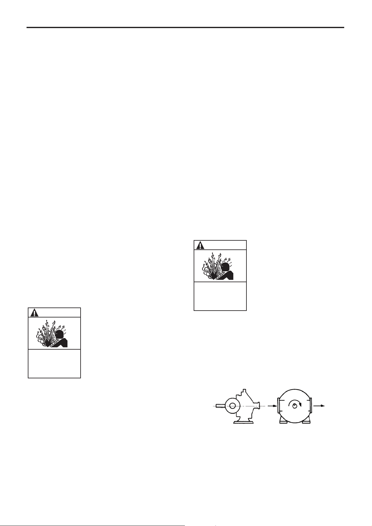
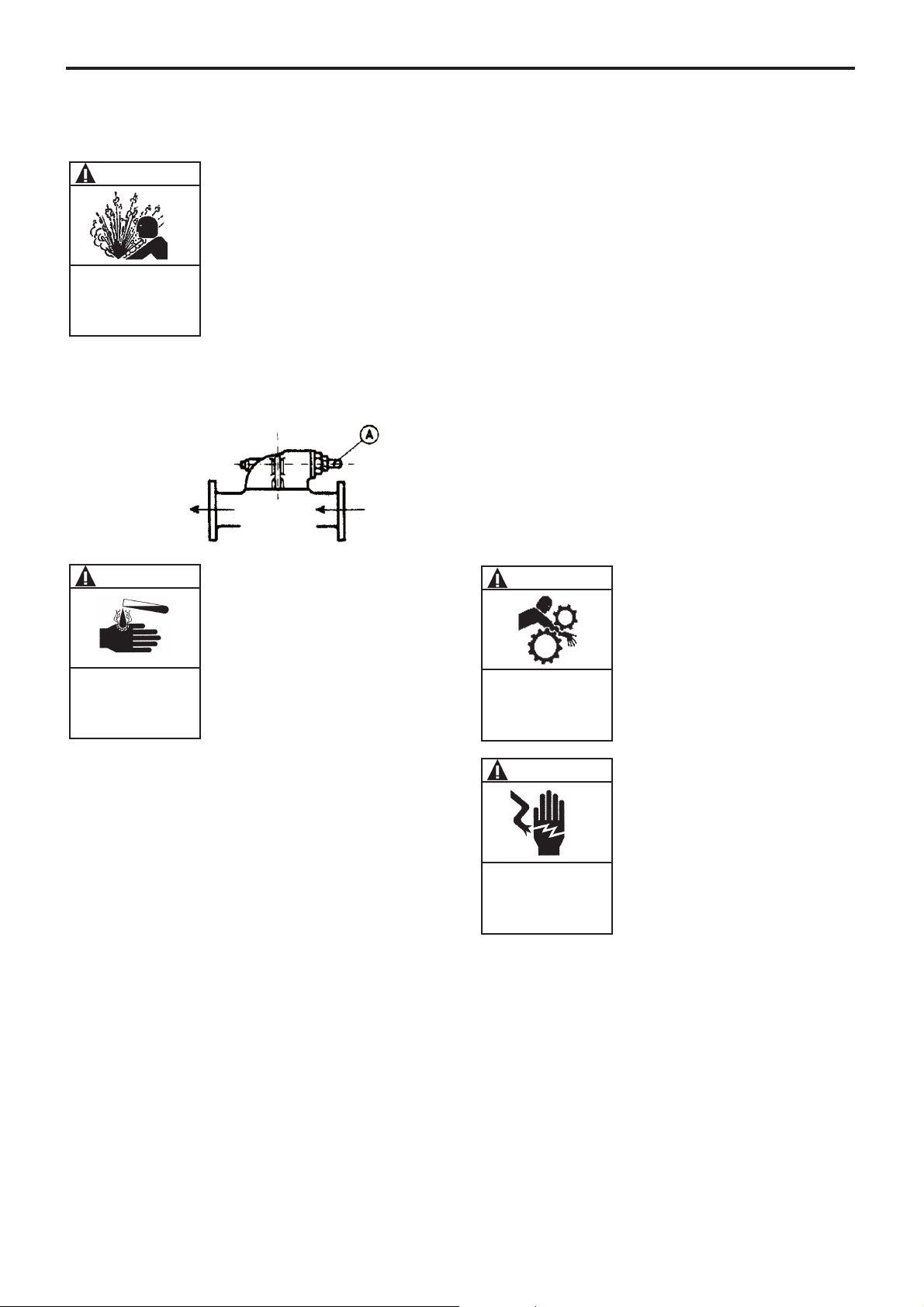
2.4 Direction of rotation
The MOUVEX pump is reversible; this allows it to always
circulate the liquid in the desired direction by choosing
the corresponding direction of rotation.
The intake and discharge sides are determined as follows :
When an observer faces the shaft, if rotation takes place
clockwise, the intake is on the left; on the contrary if the
rotation is anticlockwise, the intake is on the right.
Figure A - Clockwise rotation
Suction
Discharge
FAILURE TO RELIEVE THE SYSTEM
PRESSURE PRIOR TO PERFORMING
ANY WORK ON THE PUMP OR THE
INSTALLATION CAN CAUSE PERSONAL
INJURY OR PROPERTY DAMAGE.
WARNING
Hazardous pressure
can cause
personal injury
or property damage.
FAILURE TO RELIEVE THE SYSTEM
PRESSURE PRIOR TO PERFORMING
ANY WORK ON THE PUMP OR THE
INSTALLATION CAN CAUSE PERSONAL
INJURY OR PROPERTY DAMAGE.
WARNING
Hazardous pressure
can cause
personal injury
or property damage.
5/19NT 1003-E00 09.12 AK O - AK I e
2. INSTALLATION (continued)
2.5 Single bypass
The single bypass protects only the pump in only one direction, but it is reversible. Cap A must be on the intake side.
This must be done before the pump is started for the first time
and revalidated if the pumping circuit changes.
Once the pump is drained, the single bypass can easily
be changed to the correct direction by dismantling the
screws of the fastening pins and by turning the bypass
180° : before locking it in its new position, make sure
that you carefully install the seals beneath it.
2.6 Double bypass
Pumps equipped with a double bypass are intended to
operate in both directions in perfect safety.
However, this means substantial reserves for the maintenance of drive parts.
Changing the direction of rotation should only be done
after completely shutting down the pump.
2.7 Cleaning
Since the pumps are delivered well greased, they must be
cleaned before starting them up (especially when transferring food products, for example).
Cleaning can be done either by circulating an appropriate
liquid, or by removing the front cover of the pump and
carefully cleaning the internal parts. (cf. § OPENING THE
PUMP).
2.8 Anchoring the pump units
The correct seating of the pump is vital for its efficient
operation and its longevity.
The surface must be resistant enough to absorb the
stresses due to the pump unit without deformation.
In the case where the unit is fastened by anchor lugs or
bolts, it must be carefully wedged to prevent any deformation of the chassis when tightening the bolts.
Deformation of the chassis will cause stress prejudicial
to the pump and the drive device and put the coupling
out of true, thereby causing vibrations, noise and premature wear. Care must be taken so that the chassis is
clear of the ground, apart from the base plates.
The chassis is equipped with a ground connection that
must be used.
We recommend leaving an unoccupied space of about
50 cm, on either end of the chassis, to permit access to
the bolts fastening the pump, reduction gear and motor
together.
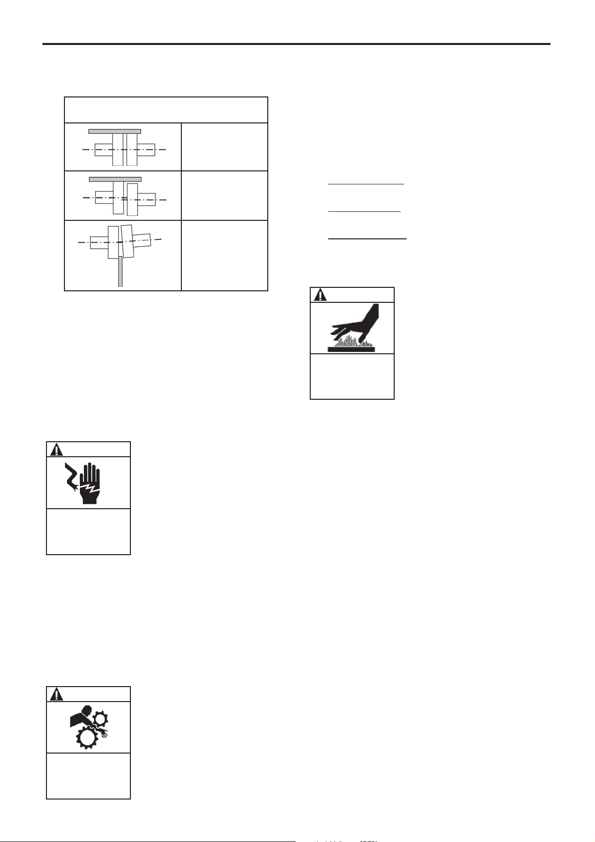
2.9 Alignment of motor / pump and reduction
gearbox / pump shafts
The motor and pump shafts are perfectly aligned in the
factory before shipment, but they must be checked and
realigned after installation if necessary.
To check the alignment and coupling, use a set square
to control the axial misalignment, and feeler gauges for
angular misalignment.
Suction
Discharge
DISCONNECT THE ELECTRICITY SUPPLY
BEFORE ANY MAINTENANCE OPERATION.
WARNING
Dangerous voltage.
Can cause
injury and death
.
OPERATION WITHOUT THE SHAFT
PROTECTOR CAN CAUSE SERIOUS
PERSONAL INJURY, MAJOR PROPERTY
DAMAGE, OR DEATH.
WARNING
Do not operate
without guard
in place.
IF PUMPING HAZARDOUS OR TOXIC
FLUIDS, THE SYSTEM MUST BE FLUSHED
PRIOR TO PERFORMING ANY SERVICE
OPERATION.
WARNING
Hazardous or toxic
fluids can cause
serious injury.
FAILURE TO RELIEVE THE SYSTEM
PRESSURE PRIOR TO PERFORMING
ANY WORK ON THE PUMP OR THE
INSTALLATION CAN CAUSE PERSONAL
INJURY OR PROPERTY DAMAGE.
WARNING
Hazardous pressure
can cause
personal injury
or property damage.
6/19NT 1003-E00 09.12 AK O - AK I e
2. INSTALLATION (continued)
The 3 figures below show the operation clearly.
It is important to control the alignment at every step of
installation in order to ensure that none of these steps
generates stress on the pump unit or the pump itself :
• after fastening on foundations
• after fastening the piping
• after the pump has operated at normal operating
temperature.
REMINDER :
Do not rely on the flexible coupling to compensate for
misalignment.
2.10 Electric motors
Check that the supply voltage matches the indications
on the motor rating plate.
Comply with the wiring diagram, make sure the wires are
rated for the power and take care with the contacts
which must be thoroughly tightened.
The motors must be protected by appropriate circuit
breakers and fuses.
Connect the regulatory ground connections.
Check the direction of rotation :
This fundamental checking of the pump must be done
without any product, with the inlet and outlet circuit open
to the air, for example, to avoid any risk of an unexpected pressure rise. Start the pump empty to check the correct operation of the connections and check that the
direction of rotation corresponds to installation's inlet
and outlet direction. Follow the instructions below if
necessary to change the direction of rotation.
Three phase motor
: switch any two wires or two phases
of the current supply.
Two phase motor
: switch the two wires of the same
phase.
Single phase motor
: comply with the instructions of the
manual supplied with the motor.
2.11 Diesel engine drive
Do not forget that these engines are not reversible. It is
therefore vital to carefully check the inlet and outlet sides
of the pump before connecting the pump unit to the
piping.
The use of diesel engines is now well known.
Nevertheless, we strongly recommend that you carefully
read the technical manuals concerning them.
DISCONNECT THE ELECTRICITY SUPPLY
BEFORE ANY MAINTENANCE OPERATION.
WARNING
Dangerous voltage.
Can cause
injury and death.
THE SURFACES CAN BE AT A TEMPERATURE LIABLE TO CAUSE INJURY
OR SEVERE DAMAGE.
CAUTION
Excessive temperature-
can cause injury or
severe damage.
OPERATION WITHOUT THE SHAFT
PROTECTOR CAN CAUSE SERIOUS
PERSONAL INJURY, MAJOR PROPERTY
DAMAGE, OR DEATH.
WARNING
Do not operate
without guard
in place.
Carry out a control on 4 points:
At the top - at the bottom - on the left - on the right
Correct
Axial alignment
out of true
Angular alignment
out of true
 Loading...