

Page 1

IB970
3rd Gen. Intel® CoreTM i7/i5
+ B75 PCH
Full Size CPU Card
USER’S MANUAL
Version 1.0
Page 2

ii
IB970 User’s Manual
Acknowledgments
AMI is a registered trademark of American Megatrends Inc.
PS/2 is a trademark of International Business Machines
Corporation.
Intel and Intel® Sandy Bridge DC/QC Processor are registered
trademarks of Intel Corporation.
Microsoft Windows is a registered trademark of Microsoft
Corporation.
Winbond a registered trademark of Winbond Electronics
Corporation.
All other product names or trademarks are properties of their
respective owners.
Page 3

IB970 User’s Manual iii
Table of Contents
Introduction ...................................................... 1
Product D escri ption ............................................................ 1
Checklist ............................................................................. 2
IB970 Specifications .......................................................... 3
Board Dimensions .............................................................. 5
Installations ...................................................... 6
Installing the CPU .............................................................. 7
Installing the Memory......................................................... 8
Setting the Jum pers............................................................. 9
Connectors on IB970 ........................................................ 14
BIOS Setup.......................................................23
Drivers Installation ......................................49
Intel Chipset Software Installation Utility ......................... 50
VGA Drivers Installation .................................................. 53
Realtek HD Audio Driver Installation .............................. 56
LAN Drivers Installation .................................................. 58
Intel® Management Engine Interface ............................... 62
Intel® USB 3.0 Drivers .................................................... 65
Appendix ...........................................................69
A. I/O Port Address Map .................................................. 69
B. Interrupt Request Lines (IRQ) ...................................... 70
C. Watchdog Timer Conf i gura ti on ................................... 71
Page 4

iv
IB970 User’s Manual
This page is intentionally left blank.
Page 5

INTRODUCTION
IB970 User’s Manual 1
Introduction
Product Description
The IB970 PICMG 1.0 full size CPU Card is based o n the latest Intel®
BD82B75 chipset. The platform supports 3rd Generation Intel® Core
i7/i5 in FCLGA1155 LGA1155 packing and features an integrated
dual-channel DDR3 m emory controller as well as a graphi cs core (4000).
Display interfaces of the CPU card include VGA CRT and DVI-D, while
24-bit dual channel LVDS is supported on IB970F and not IB970. The
edge connector s ar e for VGA CRT, USB 2.0, U SB 3 . 0 and dual Gigabit
LAN RJ45 connectors. One SATA III port and five SATA II ports are
available. Expansion slot is pro vid e d wit h a Mini PCIe socket on the
component side. Two serial ports and a parallel port are sup port ed.
Dimensions of the board are 338mm x 122mm.
IB970 FEATURES:
• Support s Intel® 3rd Generat ion Core i7/i5 DT processo rs
• Two DDR3 DIMM, 1066/1333/1600MHz, Max. 16GB
• Dual Intel
®
PCI-Expre ss Giga b it LAN
• Integrated Graphics for CRT, DVI-D, LVDS displays
• 5x SAT A 2.0, 1x SATA III, 6x USB 2.0, 3x USB 3.0
2x COM, p ara llel por t
• Mini PCI e s ocket, iSMA RT, Wa tchd og timer, Dig ital I/O
Page 6

INTRODUCTION
2
IB970 User’s Manual
Checklist
Your IB970 package should include the items listed below.
• The IB970 Full-Size CPU Card
• This User’s Manual
• 1 CD containing c hipse t drivers and flas h memory utility
Page 7
INTRODUCTION
IB970 User’s Manual 3
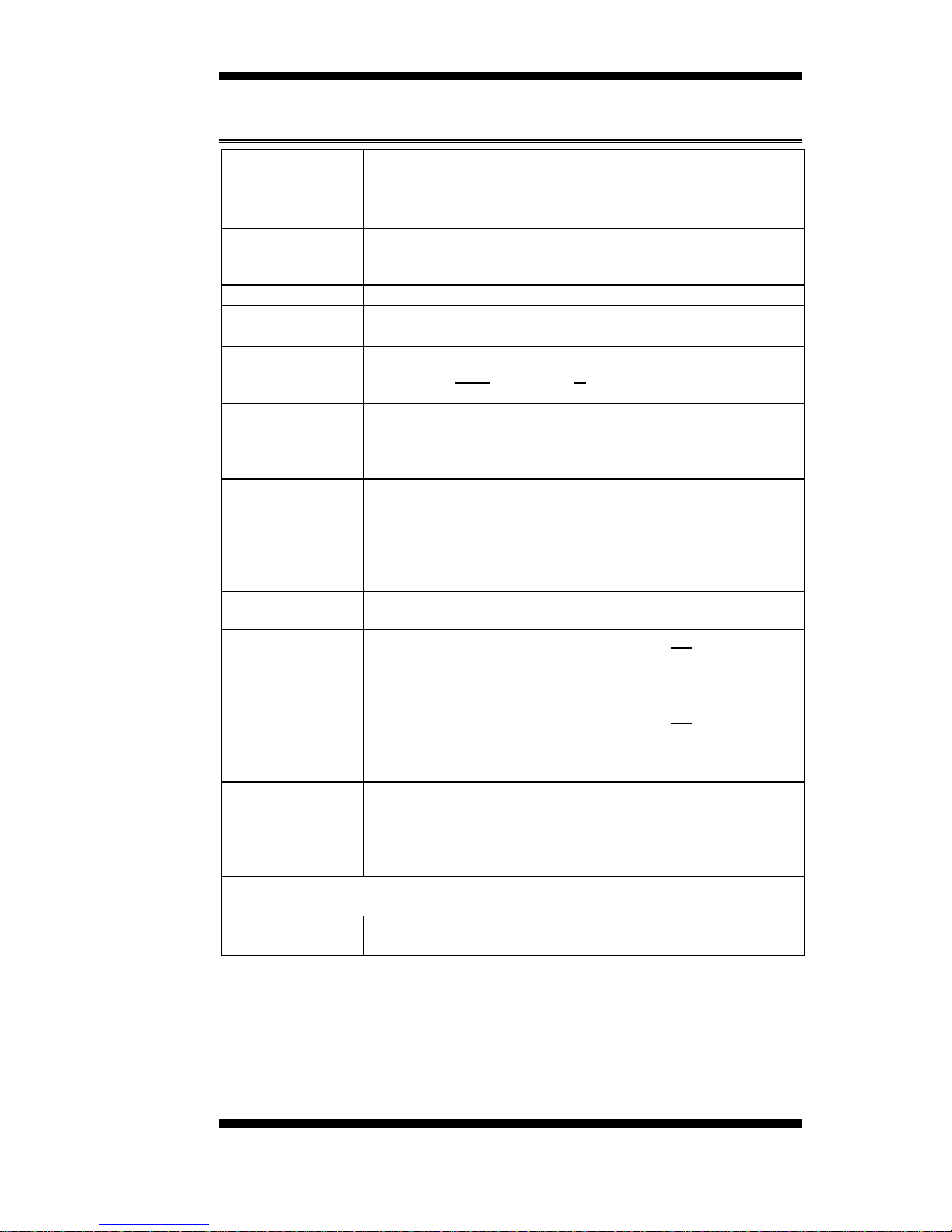
IB970 Specifications
Product Name
IB970F [with LVDS support]
IB970 [w/o LVDS , w/oTPM]
IB970RF [with LVDS support, Q77 on board]
Form Factor
PICMG 1.0 Full size CPU card
CPU Type
- 3rd Generation Intel® CoreTM i7/i5 DT processor
- FCLGA1155 package [37.5 mm x 37.5mm]
- TDP: QC= 77W/65W/45W/35W
CPU Speed
2.3GHz ~ 3.4GHz (TDP=45W~77W)
BIOS
AMI BIOS, support ACPI Function
CPU Socket
LGA1155
Chipset
Intel® BD82B75 PCH [IB970F / IB970]
Intel® BD82Q77 PCH [IB970RF]
27mm x 27mm, FCBGA942 (TDP=6.7W)
Memory
3rd Generation Intel® CoreTM i7/i5 DT processor integrated
memory controller
DDR3-1600 MHz (Non-ECC)
- DIMM x 2, M ax. 16GB
Display
interface
3rd Generation Intel® CoreTM i7/i5 DT processor integrated
HD graphics 4000
- VGA
- DVI-D (via level-shifter ASM1442, pin-header onboard)
- LVDS (Chrontel CH7511 via DP, supports 24-bit dual
channel)[IB970F only]
LAN
1. Intel® 82579V GbE PHY x1
2. Intel® 82583V PCI-e Gigabit LAN controller x 1
USB
Intel® BD82B75/Q77 PCH integrated USB 2.0 hos t control ler
- 4 ports thru onboard pin-header
- 1 port @ rear panel I/O
- 1 port via MiniPCIe @ component side
Intel® BD82B75/Q77 PCH integrated USB 3.0 host control l er
- 1 port @ rear panel I/O
- 2 ports via onboard box header [2*10 pins box header,
Blue color]
Serial ATA
Ports
Intel® BD82B75/Q77 PCH built-in SATA controller
1 x SATAIII + 5 x SATAII (one SATA II shared with
mSATA)[IB970F/IB970]
2 x SATAIII + 4 x SATAII (one SATA II shared with
mSATA)[IB970RF]
PCI-to-ISA
bridge
ITE IT8888G x1 for high dri ve ISA bus
Audio
Intel® BD82B75/Q77 PCH built-in high definition audio w/
Realtek ALC662 Codec
Page 8
INTRODUCTION
4
IB970 User’s Manual
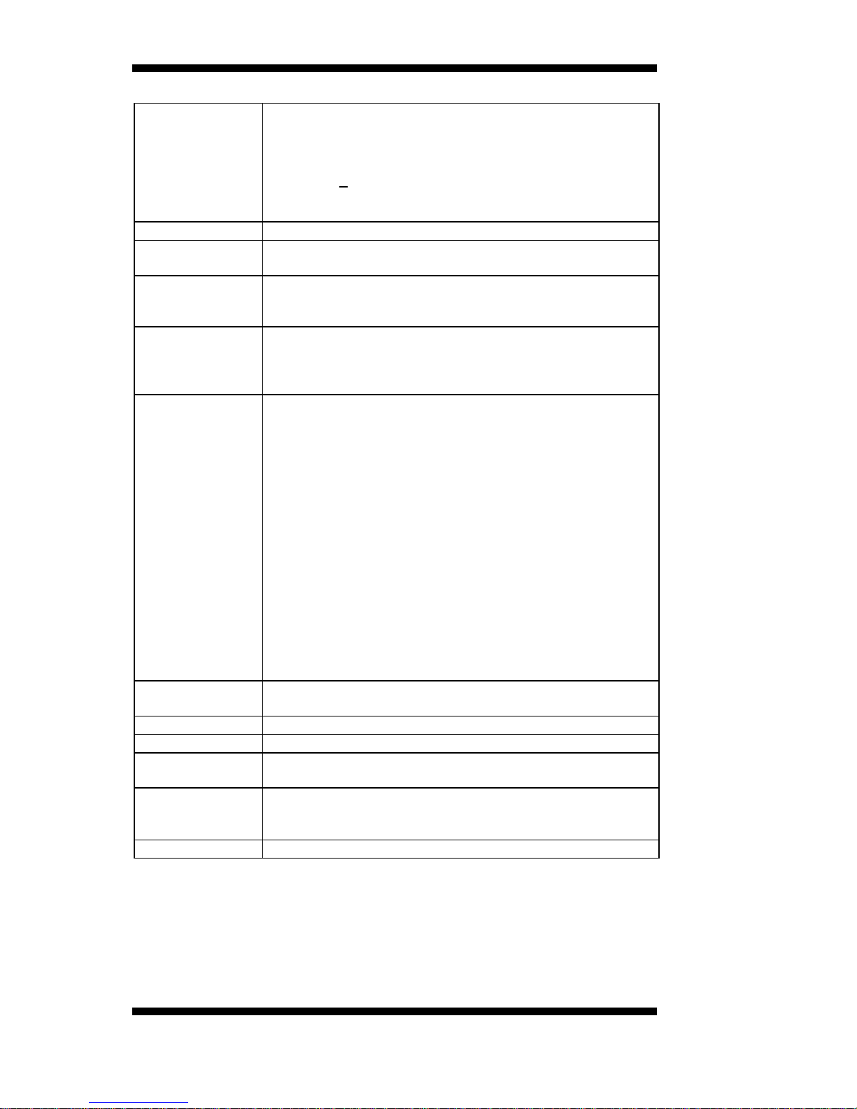
LPC I/O
Fintek F81866AD-I (128-pin LQFP [14mm x 14 mm])
- COM1 (RS232/422/485), jumperless design (SP339)
- COM2/COM3/COM4 (RS232),
- Hardware monitoring (2 thermal inputs,4 voltage monitor
inputs & 2 Fan headers, one PWM fan type = 4-pin for
CPU FAN; one DC fan type = 3-pin for SYS FAN)
- Support Parallel por t (share with one fan control)
Digital IO
4 in & 4 out
Keyboard/
Mouse
Supports PS/2 Keyboard/Mouse thru onboard pin-header
Expansion
Slots
Mini PCIe socket x1@ component side [Full-sized, reserved
one mounti ng for half-si zed card also], [Su pport USB client &
mSATA]
Edge
Connector
DB15 x1 for VGA
RJ45 x 2 for LAN 1 & 2
USB 2.0 x 1
USB 3.0 x 1
Onboard
Header/
Connector
DF11-20 pins pin-header x1 for DVI-D
DF13-20 pins pin-header x 2 for 24-bit dual channel
LVDS (IB970F/RF)
1x 4 pins bo x header x 1 fo r LCD brightness control
(IB970F/RF only)
2x13 pins bo x-header x 1 f o r Printer (IB970 only)
DF11-20 pins box-header x1 for COM1/2
DF11-20 pins box-header x1 for COM3/4
2x4 pins pin-header x 2 for USB 2.0 #1-4
2x6 pins pin-header x1 for Audio (Line-Out, Line-In & Mic)
2 x 5 pins pin-header x 1 for Digital I/O
2 x 5 pins pin-header x 1 for PS/2 KB/MS
4 pins pin-header x1 for CPU fan (PWM smart fan)
3 pins pin-header x1 for system fan
SATA x 6 (Black connectors for SATA2; Blue connectors for
SATA 3)
2X10 pins pin-header x 1 for front panel indicators
Watchdog
Timer
Yes (256 segments, 0, 1, 2…255 sec/min)
System Voltage
+5V, +3.3V, +12V, -12V & 5VSB
RoHS
Yes
iSMART
Thru MCU
Support Auto-scheduler & Power resume feature
Others
- LAN wake up
- Reserved extra mounting h o le as IB960
- TPM 1.2 supported (IB970F/ RF on board)
Board Size
338mm x 122mm
Page 9
INTRODUCTION
IB970 User’s Manual 5
[
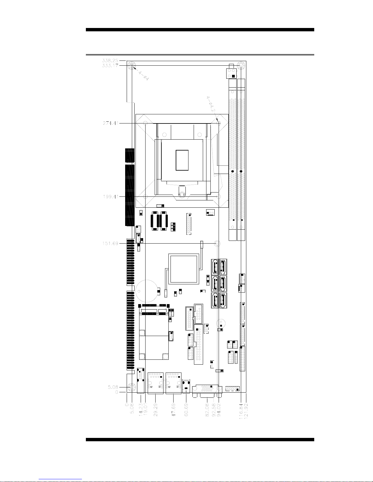
Board Dimensions
Page 10

INSTALLATIONS
6
IB970 User’s Manual
Installations
This section provides information on how to use t he ju mpe rs and
connectors on the IB970 in order to set up a workable sy stem. The topics
covered are:
Installing th e C PU................................................................................ 7
Installing th e M emory .......................................................................... 8
Sett ing the Jumpers.............................................................................. 9
Co nne ct or s on IB970 ......................................................................... 14
Page 11
INSTALLATIONS
IB970 User’s Manual 7
Installing th e CPU
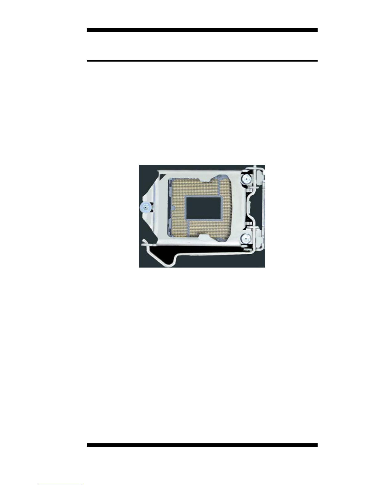
The IB970 board supports an LGA1155 Socket (shown be low) for Intel
Sandy Bridge processo r s.
To install the CPU, unlock fi rst the socket by pressin g the lever sideways,
then lift it up to a 90-degree. T hen, p os ition t he CP U abo ve the so cket
such that the CPU corner aligns with the gold triangle matching the
socket corner with a small triangle. Carefully insert the CPU into the
socket and push down the lever to secure the CPU. T hen, install the heat
sink a nd fan.
NOTE:
Ensure that the CPU heat sink and the CPU top surface are in
total contact to avoid CPU overheating problem that would
cause your system to hang or be unstable.
Page 12
INSTALLATIONS
8
IB970 User’s Manual
Installing the Memory
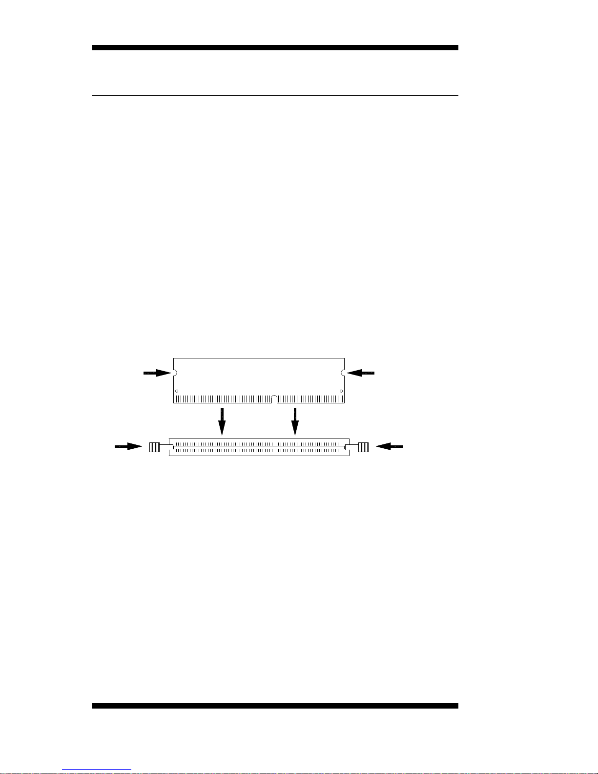
The IB970 board supports two DD R3 me mor y soc ket for a maximu m
t ota l memory of 8GB in DDR3 DIMM memory type.
Installing and Removing Memory M od ules
To install the DDR3 modules, locate the memory slot on the board and
perform the following steps:
1. Hold the DDR3 module so that the key of the DDR3 module aligned
with that on the me mory slot.
2. Gently push the DDR3 module in an upr ight position until the clips of
the slot close to ho ld the DDR3 module in place when the DDR3
module touches the bottom of the slot.
3. To remove the DDR3 mod ule, p ress the c lips with both hands .
DDR3 Module
Lock
Lock
Lock
Lock
Page 13

INSTALLATIONS
IB970 User’s Manual 9
Setting the Jumpers
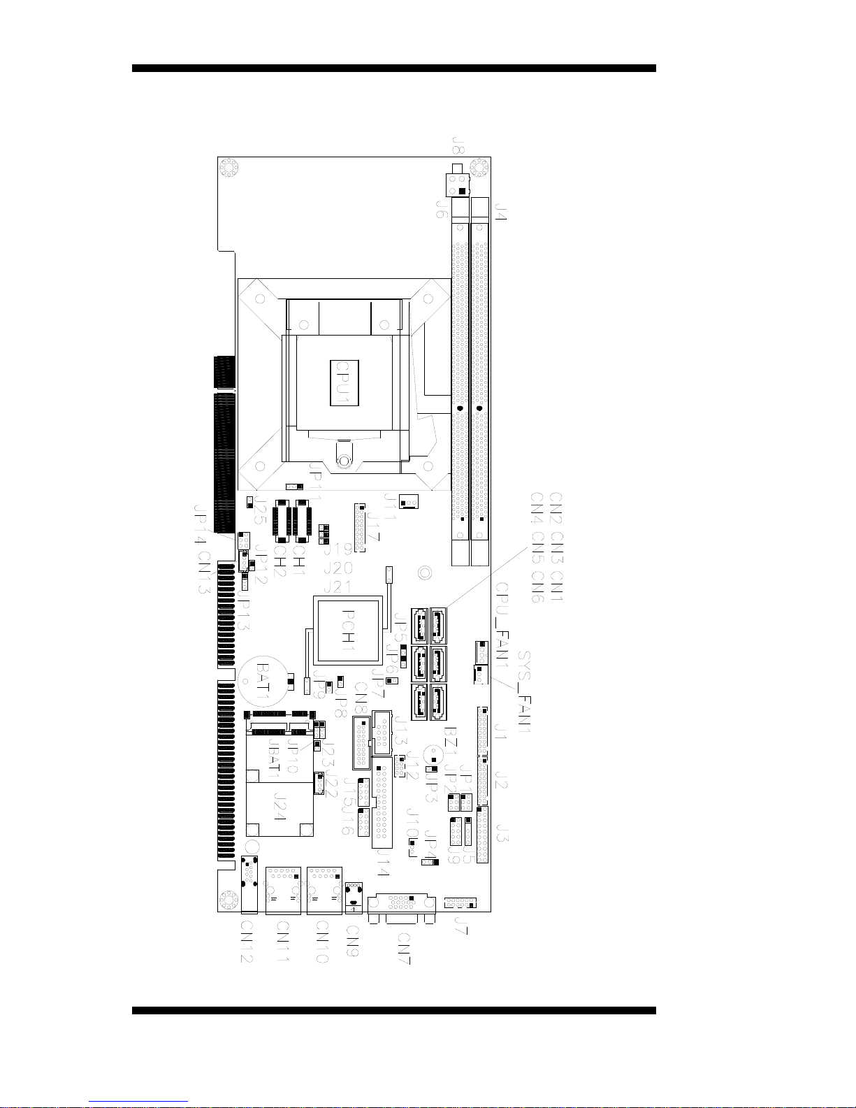
Jumpers are used on IB970 to select various settings and features
according to your needs and applications. Contact your supplier if you
have d oubts abo ut the best configurat ion for you r needs. The following
lists the connecto r s on IB970 and their respective functions.
Jumper Locations on IB970 ............................................................... 10
JP1: COM1 RS232 RI/+5V/+12V Power Setting ............................... 11
JP2: COM2 RS232 RI/+5V/+12V Power Setting ............................... 11
JP3: Power On Type .......................................................................... 11
JP8: Flash Descriptor S ecur ity Override (Factory use only) ................ 11
JP11: LVDS Panel Power Selection ................................................... 12
JP12: LVDS EEP ROM Flash Connector (facto r y use only) ................ 12
JP14: BL Voltage Setting .................................................................. 12
JP15: BL_ADJ_LEVEL Setting ......................................................... 12
JBAT1: Clear CMOS Cont e nt s .......................................................... 12
SW1: LVDS Panel Typ e Setting ........................................................ 13
Page 14
INSTALLATIONS
10
IB970 User’s Manual
Jumper Locations on IB970
Page 15
INSTALLATIONS
IB970 User’s Manual 11
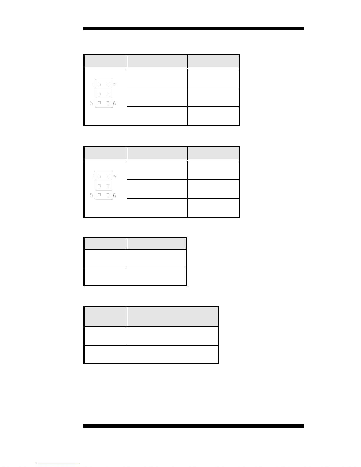
JP1: COM1 RS232 RI/+5V/+12V Power Setting
JP1 Setting Function
Pin 1-3
Short/Closed
+12V
Pin 3-4
Short/Closed
RI
Pin 3-5
Short/Closed
+5V
JP2: COM2 RS232 RI/+5V/+12V Power Setting
JP2 Setting Function
Pin 1-3
Short/Closed
+12V
Pin 3-4
Short/Closed
RI
Pin 3-5
Short/Closed
+5V
JP3: Power On Type
JP3
Function
Open
ATX Mo de
(Default)
Close AT Mod e
JP8: Flash Descriptor Security Overrid e (Factory use only)
JP8
Flas h Descriptor
Security Overri de
Open
Disabled
(Default)
Close Enabled
Page 16
INSTALLATIONS
12
IB970 User’s Manual
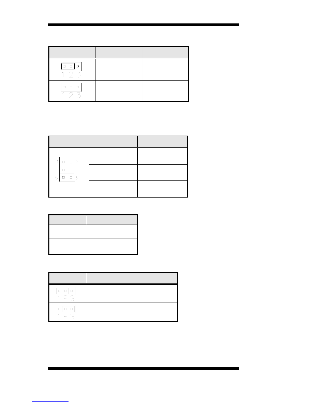
JP11: LVDS Panel Power Selection
JP11 Setting Panel Voltage
Pin 1-2
Short/Closed
3.3V (default)
Pin 2-3
Short/Closed
5V
JP12: LVDS EEPROM Flash Connector (factory use only)
JP14: BL Voltage Setting
JP14 Setting Function
Pin 1-2
Short/Closed
+3.3V
Pin 3-4
Short/Closed
+5V
Pin 5-6
Short/Closed
+12V(Default)
JP15: BL_ADJ_LEVEL Setting
JP15
Function
Open
3.3V
Close
5V (default )
JBAT1: Clear CMOS Contents
JBAT1 Setting Function
Pin 1-2
Short/Closed
Normal
Pin 2-3
Short/Closed
Clear CMOS
Page 17

INSTALLATIONS
IB970 User’s Manual 13
SW1: LVDS Panel Type Setting
SW1-4
SW1-3
SW1-2
SW1-1
Panel Type
ON ON ON ON 800*600 18bit 1c h
ON ON ON OFF 1024*768 18bit 1ch
ON ON OFF ON 1024*768 24bit 1ch
ON ON OFF OFF 1280*768 18bit 1ch
ON OFF ON ON 1280*800 18bit 1ch
ON OFF ON OFF 1280*960 18bit 1ch
ON OFF OFF ON 1280*1024 24bit 2ch
ON OFF OFF OFF 1366*768 18bit 1ch
OFF ON ON ON 1366*768 24bit 1ch
OFF ON ON OFF 1440*900 24bit 2ch
OFF ON OFF ON 1440*1050 24bit 2ch
OFF ON OFF OFF 1600*900 24bit 2ch
OFF OFF ON ON 1680*1050 24bit 2ch
OFF OFF ON OFF 1600*1200 24bit 2ch
OFF OFF OFF ON 1920*1080 24bit 2ch
OFF OFF OFF OFF 1920*1200 24bit 2ch
Page 18

INSTALLATIONS
14
IB970 User’s Manual
Connectors on IB970
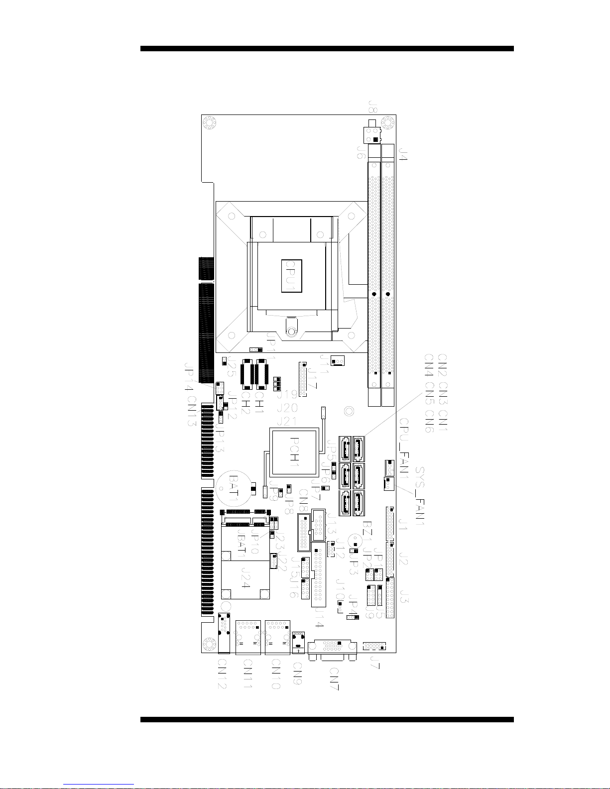
Connector Locations on IB970 .......................................................... 15
CN1, CN3, CN4, CN5, CN6: SATA2 Connectors ............................. 16
CN2 : SATA3 C onne ct ors .................................................................. 16
CN7: DB-15 V GA Connector ............................................................ 16
CN8: USB3 Connecto r ...................................................................... 16
CN9: USB2. 0 Connecto r ................................................................... 16
CN10: Gigabit LAN (Intel 82579V)................................................... 16
CN11: Gigabit LAN (Intel 82583V)................................................... 16
CN12: USB3.0 Connector ................................................................. 16
CN13: LCD Backlight Connector ...................................................... 17
J1: COM3, COM4 Serial Port ( DF11 Connector) .............................. 17
J2: COM1, COM2 Serial Port ( DF11 Connector) .............................. 17
J3: Fro nt Panel Funct ion Connector ................................................... 18
J7: Ext erna l Audio Conne c tor ............................................................ 18
J8: ATX 12V Power Connector ......................................................... 18
J9: Digita l I/O .................................................................................... 18
J10: PCI LAN Wake up Co nnector .................................................... 19
J11: External ATX Power Co nnector ................................................. 19
J12: PS/2 Keyboard and PS/2 Mouse Connectors .............................. 19
J13: SPI Flash Connector (Factory use only) ...................................... 19
J14 : Pa rallel Port ............................................................................... 19
J15, J16: USB Connectors ................................................................. 20
J17: DVI-D Por t ................................................................................ 20
J22: MCU Flash Connector ( factory use only).................................... 20
J24: Mini PCI E Connec tor ................................................................. 20
CPU_FAN1: CPU Fan Power Connecto r ........................................... 20
SYS_FAN1: System Fan1 P ower Co nnecto r...................................... 20
CH1, CH2: LVDS Connectors ........................................................... 21
Page 19
INSTALLATIONS
IB970 User’s Manual 15
Connector Locations on IB970
Page 20
INSTALLATIONS
16
IB970 User’s Manual
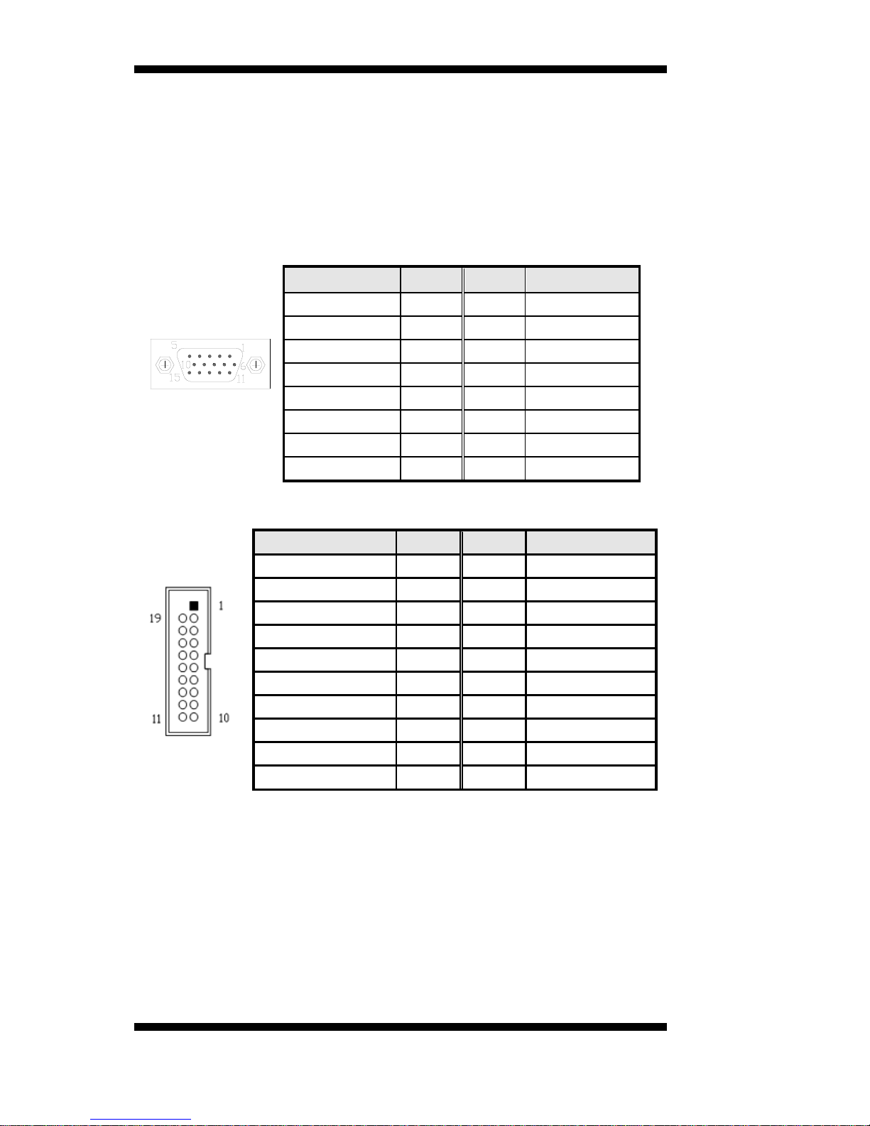
CN1, CN3, CN4, CN5, CN6: SATA2 Connectors
CN2: SATA3 Connectors
CN3: SATA3 Connectors (IB970RF only)
CN7: DB-15 VGA Connector
Signal Name
Pin #
Pin #
Signal Name
Red
1 2 Green
Blue
3 4 N.C.
GND
5 6 GND
GND
7 8 GND
VCC
9
10
GND
N.C.
11
12
DDCDATA
HSYNC
13
14
VSYNC
DDCCLK
15
CN8: USB3 Connector
Signal Name
Pin #
Pin #
Signal Name
Vcc
1 X
P1_SSRX-
2
19
Vcc
P1_SSRX+
3
18
P2_SSRX-
GND
4
17
P2_SSRX+
P1_SSTX-
5
16
GND
P1_SSTX+
6
15
P2_SSTX-
GND
7
14
P2_SSTX+
P1_U2_D-
8
13
GND
P1_U2_D+
9
12
P2_U2_D-
NC
10
11
P2_U2_D+
CN9: USB2.0 Connector
CN10: Gigabit LAN (Intel 82579V)
CN11: Gigabit LAN (Intel 82583V)
CN12: USB3.0 Connector
Page 21
INSTALLATIONS
IB970 User’s Manual 17
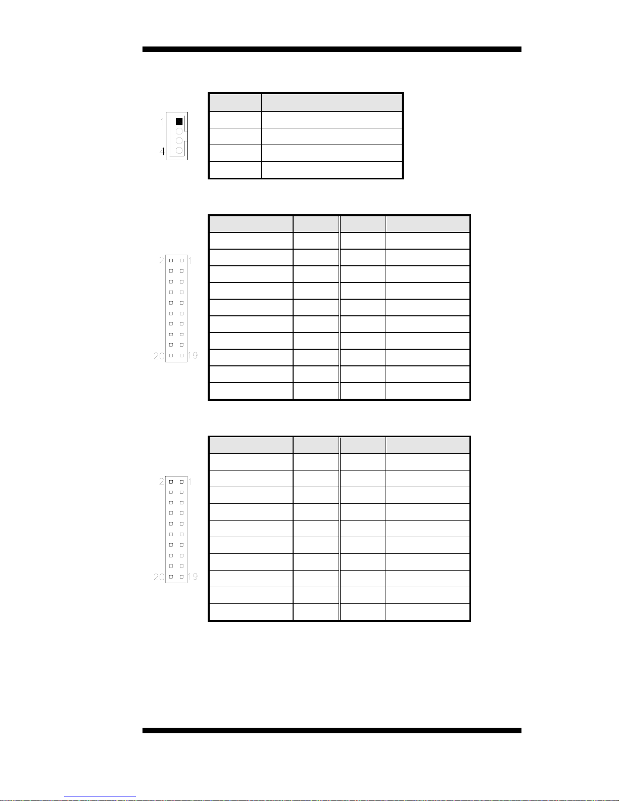
CN13: LCD Backlight Connector
Pin #
Signal Name
1
Backlight P ower
2
Backlight En able
3
Brightness Contro l
4
Ground
J1: COM3, COM4 Serial Port (DF11 Connector)
Signal Name
Pin #
Pin #
Signal Name
DSR3
2 1 DCD3
RTS3
4 3 RXD3
CTS3
6 5 TXD3
RI3
8 7 DTR3
NC
10 9 Ground
DSR4
12
11
DCD4
RTS4
14
13
RXD4
CTS4
16
15
TXD4
RI4
18
17
DTR4
NC
20
19
Ground
J2: COM1, COM2 Serial Port (DF11 Connector)
Signal Name
Pin #
Pin #
Signal Name
DSR1
2 1 DCD1
RTS1
4 3 RXD1
CTS1
6 5 TXD1
RI1
8 7 DTR1
NC
10 9 Ground
DSR2
12
11
DCD2
RTS2
14
13
RXD2
CTS2
16
15
TXD2
RI2
18
17
DTR2
NC
20
19
Ground
Page 22
INSTALLATIONS
18
IB970 User’s Manual
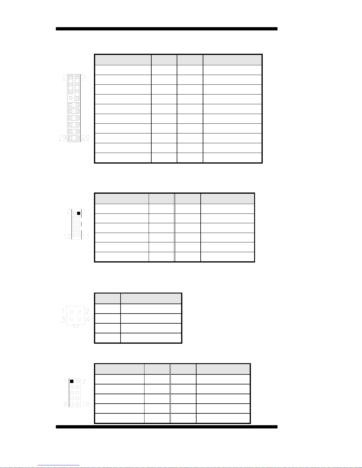
J3: Front Panel Function Connect or
Signal Name
Pin #
Pin #
Signal Name
VCC
1 2 Speaker Out
NC
3 4 NC
Ground
5 6 Ground
NC
7 8 VCC
Ground
9
10
NC
Ground
11
12
NC
Ground
13
14
PWR_SW
NC
15
16
NC
Ground
17
18
RST
HDD LED +
19
20
HDD LED -
J7: External Audio Connector
J7 is a 12-pin header that is used to connect to the opt ional audio cable.
Signal Name
Pin #
Pin #
Signal Name
LINE OUT_L
1 2 LINE OUT_R
JD_FRONT
3 4 Ground
LINE IN_L
5 6 LINE IN R
JD LINE IN
7 8 Ground
MIC-L
9
10
MIC-R
JD MIC1
11
12
Ground
J8: ATX 12V Power Connector
This connector supplies the CPU oper ating voltage.
Pin #
Signal Name
1
Ground
2
Ground
3
+12V
4
+12V
J9: Digital I/O
Signal Name
Pin #
Pin #
Signal Name
GND
1 2 VCC
OUT3
3 4 OUT1
OUT2
5 6 OUT0
IN3
7 8 IN1
IN2
9
10
IN0
Page 23
INSTALLATIONS
IB970 User’s Manual 19
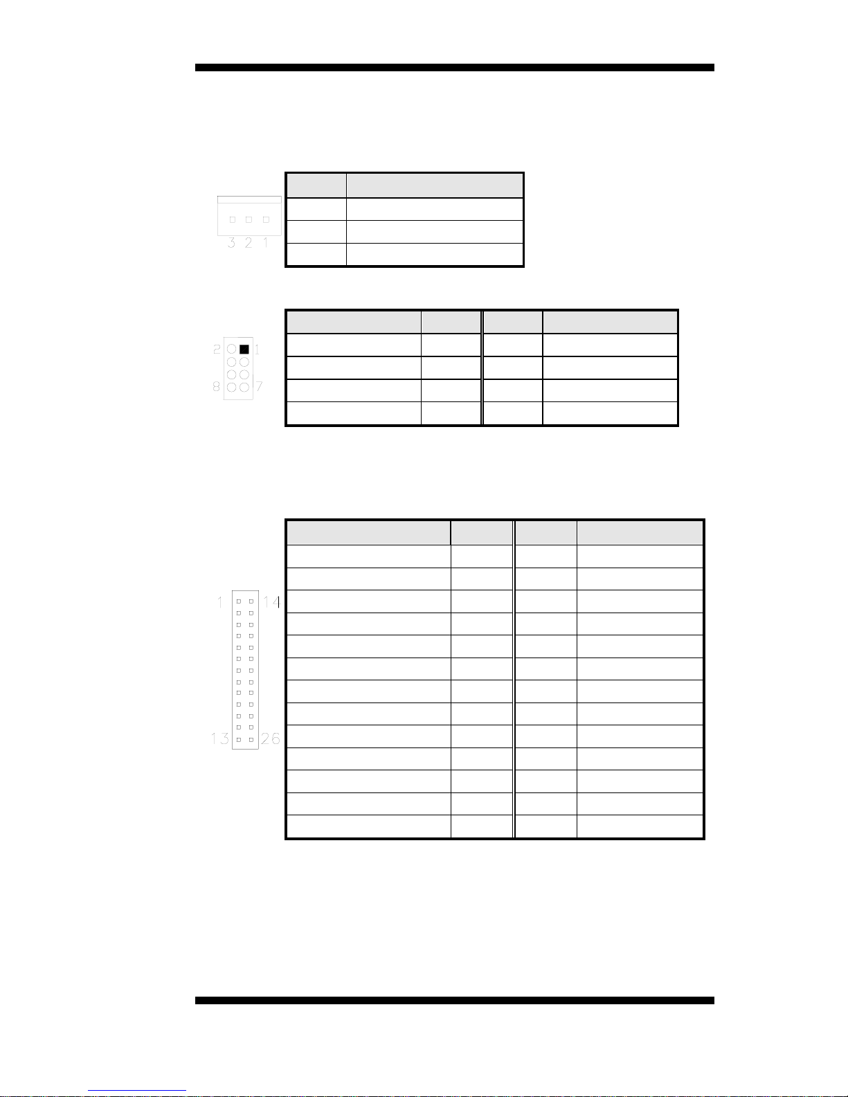
J10: PCI LAN Wake up Connector
J11: External ATX Power Connector
Pin #
Signal Name
1
Ground
2
PS-ON ( soft on/off)
3
5VSB (Standby +5V)
J12: PS/2 Keyboard and PS/2 Mouse Connectors
Signal Name
Pin #
Pin #
Signal Name
Vcc
2 1 VCC
KB_DATA
4 3 MS_DATA
KB_CLK
6 5 MS_CLK
Ground
8 7 Ground
J13: SPI Flash Connector (Factory use only)
J14: Parallel Port
Signal Name
Pin #
Pin #
Signal Name
Line pr inter s tro be
1
14
AutoFeed
PD0, parallel data 0
2
15
Error
PD1, parallel data 1
3
16
Initialize
PD2, parallel data 2
4
17
Select
PD3, parallel data 3
5
18
Ground
PD4, parallel data 4
6
19
Ground
PD5, parallel data 5
7
20
Ground
PD6, parallel data 6
8
21
Ground
PD7, parallel data 7
9
22
Ground
ACK, acknowledge
10
23
Ground
Busy
11
24
Ground
Paper empty
12
25
Ground
Select
13
26
Ground
Page 24
INSTALLATIONS
20
IB970 User’s Manual
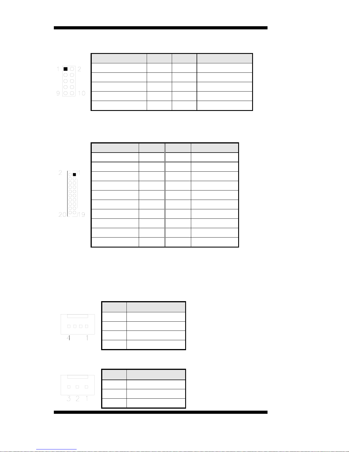
J15, J16: USB Connectors
Signal Name
Pin #
Pin #
Signal Name
VCC
1 2 VCC
D0-
3 4 D1-
D0+
5 6 D1+
Ground
7 8 Ground
KEY
9
10
NC
J17: DVI-D Port
J17 is a 20-pin header that is used to connect to the optional DVI-D cable.
Signal Name
Pin #
Pin #
Signal Name
TDC1#_B
2 1 TDC1_B
Ground
4 3 Ground
TLC#_B
6 5 TLC_B
5V
8 7 Ground
N.C.
10 9 HPDET_B
TDC2#_B
12
11
TDC2_B
Ground
14
13
Ground
TDC0#_B
16
15
TDC0_B
N.C.
18
17
N.C.
SC_DDC_B
20
19
SD_DDC_B
J22: MCU Flash Connector (factory use only)
J24: Mini PCIE Connector
CPU_FAN1: CPU Fan Power Connector
Pin #
Signal Name
1
Ground
2
+12V
3
Rotation detection
4
Control
SYS_FAN1: System Fan1 Power Connector
Pin #
Signal Name
1
Ground
2
+12V
3
Rotation detection
Page 25
INSTALLATIONS
IB970 User’s Manual 21
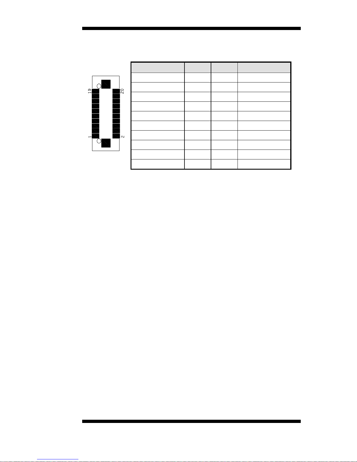
CH1, CH2: LVDS Connectors
Signal Name
Pin #
Pin #
Signal Name
N.C
19
20
N.C
ENABLE
17
18
LCD_PWR
CLK+
15
16
CLK-
GND
13
14
GND
LD2+
11
12
LD2-
LD3+
9
10
LD3-
GND
7 8 LCD_PWR
LD1+
5 6 LD1-
GND
3 4 GND
LD0+
1 2 LD0-
Page 26

INSTALLATIONS
22
IB970 User’s Manual
This pag e is intentionally le f t blank .
Page 27

BIOS SETUP
IB970 User’s Manual 23
BIOS Setup
This chapter descr ibes t he different settings available in the AMI BIOS
that comes with the board. The topics covered in this chapter are as
follows:
BIOS Introduction ............................................................................. 24
BIOS Setup ....................................................................................... 24
Advanced Settings ............................................................................. 26
Chipset Settings ................................................................................. 37
Boot Settings ..................................................................................... 44
CSM parameters ................................................................................ 45
Security Settings ................................................................................ 46
Save & Exit Settings .......................................................................... 47
Page 28

BIOS SETUP
24
IB970 User’s Manual
BIOS Introduction
The BIOS (Basic Input/Output System) installed in your computer
system’s ROM supports Intel processors. The BIOS provides critical
low-level support for a st andard device such as disk drives, serial po rts
and parallel port s. It also password pro t ect ion as well as special support
for deta iled f ine-tu ning of t he chipse t c ontrolling the entir e syst em.
BIOS Setup
The BIOS provides a Setup utility program for specifying the system
configurations and settings. The BIOS ROM of the system stores the
Se t u p utility. When yo u turn o n the computer, the BI OS is immediately
activated. Pressing the <Del> key immediately allows you to enter the
Setup utility. If you are a little bit late pressing the <Del> key, POST
(Powe r O n Self Test) w ill continue with its t es t rou tines, t hus preve nting
you from invoking the Setup. If you still wish to enter Setup, restart the
system by pressing the ”Reset” button or simultaneously pressing the
<Ctrl>, <Alt> and <Delete> keys. You can also restart by turning the
system Off and back On again. The following message will appear on the
screen:
Press <DEL> to Enter Setup
In general, y ou press the arrow keys to highl i gh t items , <Enter> to select,
the <PgUp> and <PgDn> keys to change entries, <F1> for help and
<Esc> to q uit.
When you e nter t he Setup utility, the Main Menu screen will appear o n
the screen. The Main Menu allows you to select from various setup
functions and exit choices.
Warning:
It is strongly recommended that you avoid making any
changes to the chipset defaults. These defaults have been
carefully chosen by both AMI
and your system manufacturer
to provide the absolute maximum performance and
reliability. Changing the defaults could cause the system to
become unstable and crash in some cases.
Page 29

BIOS SETUP
IB970 User’s Manual 25
Main Settings
Aptio Setup Utility – Copyright © 2011 American Megatrends, Inc.
Main
Advanced Chipset Boot Security Save & Exit
BIOS Information
Choose the system default
language
→ ← Select Screen
↑↓
Select Item
Enter: Select
+- Change Field
F1: General Help
F2: Previous Values
F3: Optimized Default
F4: Save ESC: Exit
Syste m Language
[English]
System Date
System Time
[Tue 01/20/ 2009]
[20:12:59]
Access Leve l
Administrator
System Language
Choose the system default language.
System Date
Set t he Date. Use Tab to switch between Data elements.
System Time
Set t he Time. Use Tab to switch between Data elements.
Page 30

BIOS SETUP
26
IB970 User’s Manual
Advanced Settings
This section allows you to configure and improve your system and allows
you to set up some system feat ures according to your p r eference.
Aptio Setup Utility
Main
Advanced
Chipset Boot Security Save & Exit
→ ← Select Screen
↑↓
Select Item
Enter: Select
+- Change Field
F1: General Help
F2: Previous Values
F3: Optimized Default
F4: Save ESC: Exit
► PCI Subsystem Settings
► ACPI Settings
► Wake up event setting
► Trusted Computing
► CPU Configuration
► SATA Configuration
► Shutdown Temperature Configuration
► iSmart Controller
► Aco us tic Management Configuration
► USB Configur ation
► F81866 Super IO Configurat ion
► F81866 H/W Monitor
► CPU PPM Configuration
PCI Subsystem Settings
Aptio Setup Utility
Main Advanced Chipset Boot Security Save & Exit
PCI Bus Driver Versio n V 2.0502
→ ← Select Screen
↑↓
Select Item
Enter: Select
+- Change Field
F1: General Help
F2: Previous Values
F3: Optimized Default
F4: Save ESC: Exit
PCI 64bit Resources Handing
Abov e 4G Decoding
Disabled
PCI Common Settings
PCI Latency Timer
32 PCI Bus Clocks
VGA Palette Snoop
Disabled
PERR# Generation
Disabled
SERR# Generation
Disabled
► PCI Express Settings
Above 4G Decoding
Enables or Disables 64bit capable devices to be decoded in above 4G
address space (only if system suppo rts 64 bit PCI decoding).
Page 31

BIOS SETUP
IB970 User’s Manual 27
PCI Latency Timer
Value to be progr ammed into P CI Latency Timer Register.
VGA Palett e Snoop
Enables or disables VGA Palette Registers Snoo ping.
PERR# Generatio n
Enables or disables PCI device to generate P ERR#.
SERR# Generation
Enables or disables PCI device to generate S ERR#.
PCI Express Settings
Change PCI Express devices settings.
PCI Express Settings
Aptio Setup Utility
Main Advanced Chipset Boot Security Save & Exit
PCI Express De vice Re giste r Settings
→ ← Select Screen
↑↓
Select Item
Enter: Select
+- Change Field
F1: General Help
F2: Previous Values
F3: Optimized Default
F4: Save ESC: Exit
Relaxed Ordering
Disabled
Extended Tag
Disabled
No Snoop
Enabled
Maximum Payloa d
Auto
Maximum Read Request
Auto PCI Express Link Register Settings
ASPM Support
Disabled
WARNING: Enabling ASPM may c ause
Disabled
some PCI-E devices to fail
Extended Synch
Disabled
Link Training Retry
5
Link Training Timeout (uS)
100 Unpopulat ed Links
Keep Link ON
Relaxed Ordering
Enables or disables PCI Express Device Relaxed Ord er ing.
Extended Tag
If ENABLED allow s device to use 8-bit Tag field as a requester .
No Snoop
Enables or disables PCI Express Device No Snoop option.
Page 32

BIOS SETUP
28
IB970 User’s Manual
Maximum Payload
Set Maximum Payload of PCI Express Device or allow System BIOS to
select the value.
Maximum Read Request
Set Maxim um Read Request Size of PCI Express Devi ce or all ow System
BIOS to select the value.
ASPM Support
Set the ASPM Level: Fo r ce L0s – Fo rce all links t o L0s State:
AUTO – BIOS aut o configure : DISABLE – Disables ASPM.
Extended Synch
If ENABLED allow s generation of Extended Synchr onization patterns.
Link Tra ining R etry
Defi nes number of Retry Attempts softwa re will ta ke to retrain the link if
previous training attempt was unsuccessful.
Link Tra ining Timeout (uS)
Defines number of Micr oseconds software will wait before po lling ‘Link
Training’ bit in Link Status register. Value range from 10 to 1000 uS.
Unpopulated Links
In order to save power, softwar e will disable unpopulated P CI E xpress
link s, if this option se t to ‘Disable Link’.
Page 33

BIOS SETUP
IB970 User’s Manual 29
ACPI Settings
Aptio Setup Utility
Main Advanced Chipset Boot Security Save & Exit
ACPI Settings
→ ← Select Screen
↑↓
Select Item
Enter: Select
+- Change Field
F1: General Help
F2: Previous Values
F3: Optimized Default
F4: Save ESC: Exit
Enable Hibernation
Enabled
ACPI Sleep State
S3 (Suspend to R…)
Lock Legacy Resources
S3 Vide o Repost
Di
sabled
Disabled
Enable Hibernation
Enabl es or Disabl es System abi li ty to Hibernate (OS/S4 Sleep State). This
opt ion may be not effective with some OS.
ACPI Sleep State
Select ACPI sleep state the system wi ll enter, when the SUSPEND button
is pressed.
Lock Legacy Resources
Enabled or Disabled Lock of Legacy Resources.
S3 Video Repost
Enable or disable S3 Video Repost.
Page 34

BIOS SETUP
30
IB970 User’s Manual
Wake up event settings
Aptio Setup Utility
Main Advanced Chipset Boot Security Save & Exit
Wake system with Fixe d Time Disabled
→ ← Select Screen
↑↓
Select Item
Enter: Select
+- Change Field
F1: General Help
F2: Previous Values
F3: Optimized Default
F4: Save ESC: Exit
Wake up hour
0
Wake up minute
0
Wake up second
0
Wake on Ring
Disabled Wake on PCI PME
Disabled
Wake on PCIE Wake Event
Disabled
Wake system with Fixed Time
Enabl es or Disables System wake on al arm event. When enabl ed, System
will wake on the hr::min:: sec specified.
Wake on PCIE PME Wake Event
The op tions are Disabled and Enabled.
Trusted Computing
Aptio Setup Utility
Main
Advanced
Chipset Boot Security Save & Exit
TPM Configuration
→ ← Select Screen
↑↓
Select Item
Enter: Select
+- Change Field
F1: General Help
F2: Previous Values
F3: Optimized Default
F4: Save ESC: Exit
TPM SUPPORT
Disabled
Current TPM Status Information
TPM SUPPORT OFF
TPM Support
This configuration is supported only with MB970VF. Enables or Disables
TPM support. O.S. will not show TP M. Res et of platform is req uire d.
Security Device Support
Enabl es or disables BIOS support for security device. O.S. will not show
Security Device. T CG E FI p r otocol and INT1A interface will not be
available.
Page 35

BIOS SETUP
IB970 User’s Manual 31
CPU Configuration
This section shows the CPU configuration parameters.
Aptio Setup Utility
Main Advanced Chipset Boot Security Save & Exit
CPU Configuration
→ ← Select Screen
↑↓
Select Item
Enter: Select
+- Change Field
F1: General Help
F2: Previous Values
F3: Optimized Default
F4: Save ESC: Exit
Intel® Core ™ i7-3770 CPU @ 3.40GHz
Processor Stepping
306a8
Microcode Revision
c
Max CPU Speed
3400 MHz
Min CPU Speed
1600 MHz
CPU Spee d
3400 MHz
Processor Cores
4
Intel HT Technology
Supported
Intel VT-x Technology
Supported
Intel SMX Technolo gy
Supported
64-bit
Supported
Hyper-threading
Enabled
Active Processor Cores
All
Limit CPUID Maximum
Disabled Exe c ute Disable Bit
Enabled
Intel Virtualization Technology
Disabled
Adjac ent Cache Line Prefetch
Enabled
Hyper-threading
Enabled for Wi ndows XP and Linux (OS optimized for Hy per-Threading
Technology) and Disabled for other OS (OS not optimized for
Hyper-Threading Technology). When Disabled, only one thread per
enabled core is enabled.
Active Processor Cores
Number of cores to enable in each processor package.
Limit CPUID Maximum
Disabled for Windows XP .
Execute Disable Bit
XD can prevent certain clas ses of m al icious buff er overfl ow attacks when
combined with a supporting OS (Windo ws Server 2003 SP1, Windo ws
XP SP2, SuSE Linux 9.2, Re33dHat Enterpr ise 3 Update 3.)
Page 36

BIOS SETUP
32
IB970 User’s Manual
Intel Virtualization Technology
When enabled , a VMM can utilize the additional hardware capabilities
provided by Vander pool Technology.
Adjacent Cache Line Prefetch
To turn on/off prefetching of adjacent cache lines.
SATA Configuration
SATA Devices Configuration.
Aptio Setup Utility
Main
Advanced
Chipset Boot Security Save & Exit
→ ← Select Screen
↑↓
Select Item
Enter: Select
+- Change Field
F1: General Help
F2: Previous Values
F3: Optimized Default
F4: Save ESC: Exit
SATA Controller(s)
Enabled
SATA Mode Selection
RAID Aggressive LPM Support
Enabled
SATA Controller Speed
Gen3
SATA Port0
Empty
Softwa re Preserve
Unknown
SATA Port1
Empty
Softwa re Preserve
Unknown
SATA Port2
Empty
Softwa re Preserve
Unknown
SATA Port3
Empty Softwa re Preserve
Unknown
SATA Port4
Empty
Softwa re Preserve
Unknown
SATA Port5
Empty
Softwa re Preserve
Unknown
SATA Controller( s)
Enable / Disable Serial ATA Controller.
SATA Mode Selection
(1) IDE Mode.
(2) AHCI Mode.
Page 37

BIOS SETUP
IB970 User’s Manual 33
Shutdown Temperature Configuration
Aptio Setup Utility
Main Advanced Chipset Boot Security Save & Exit
→ ← Select Screen
↑↓
Select Item
Enter: Select
+- Change Field
F1: General Help
F2: Previous Values
F3: Optimized Default
F4: Save ESC: Exit
APCI Shutdown Tempe r ature
Disabled
ACPI Shutdown Temperature
The defa ult se tting is Dis abled.
iSmart Controller
Aptio Setup Utility
Main Advanced Chipset Boot Security Save & Exit
iSmart Controller
→ ← Select Screen
↑↓
Select Item
Enter: Select
+- Change Field
F1: General Help
F2: Previous Values
F3: Optimized Default
F4: Save ESC: Exit
Power-On after Power failure
Disable Schedule S lot 1
None
Schedule S lot 2
None
ISmart Controller
Setup the power on time fo r the system.
Schedule Slot 1 / 2
Setup the hour/minute for system power on.
Page 38

BIOS SETUP
34
IB970 User’s Manual
Acoustic Management Configuration
Aptio Setup Utility
Main Advanced Chipset Boot Security Save & Exit
Aco us tic Management Configuration
→ ← Select Screen
↑↓
Select Item
Enter: Select
+- Change Field
F1: General Help
F2: Previous Values
F3: Optimized Default
F4: Save ESC: Exit
Acoustic Management
Disabled
USB Configuration
Aptio Setup Utility
Main
Advanced
Chipset Boot Security Save & Exit
USB Configur ation
→ ← Select Screen
↑↓
Select Item
Enter: Select
+- Change Field
F1: General Help
F2: Previous Values
F3: Optimized Default
F4: Save ESC: Exit
USB Devices:
2 Hubs
Legacy USB Support
Enabled
USB3.0 Suppo r t
Enabled
XHCI Hand-off
Enabled
EHCI Hand-off
Enabled
Port 60/64 Emulation
Enabled USB hardware delays and time-outs:
USB Transfer time-out
20 sec
Device reset t ine-out
20 sec
Device power-up delay
Auto
Legacy USB Support
Enables Legacy USB support.
AUTO opt ion disables legacy support if no USB devices are connected.
DISABLE option will keep USB devices availa ble only for E FI
applications.
USB3.0 Support
Enable/Disable USB3.0 (XHCI) Controller support.
XHCI Hand-off
This is a workaround for OS e s without XHCI ha nd-off support. The
XHCI ownership change should be claimed by XHCI driver.
Page 39

BIOS SETUP
IB970 User’s Manual 35
EHCI Hand-off
Enabled/Disabled. This is a workaround for OSes without EHCI hand-off
support. The EHCI ownership chan ge sh ould be cl ai m ed by EHCI driver.
Port 64/60 Emulation
Enables I/O port 60h/64h emulation support. This should be enabled for
the complete USB keyboard legacy support for no n-USB awar e OS es.
USB Transfer time-out
The time-out value for Control, Bulk, and Interrupt t ransfers.
Device reset tine-out
USB mass Storage device start Unit command time-out.
Device power-up delay
Maximum t ime the device will take before it proper ly reports itself to the
Host C on trol l e r. ‘Auto’ uses def ault value: for a Root port it is 100m s , for
a Hub port the delay is take n fr om Hu b descriptor.
F81866 Super IO Configuration
Aptio Setup Utility
Main Advanced Chipset Boot Security Save & Exit
Super IO Configuration
→ ← Select Screen
↑↓
Select Item
Enter: Select
+- Change Field
F1: General Help
F2: Previous Values
F3: Optimized Default
F4: Save ESC: Exit
F81866 Super IO Chip
F81866
► Seria l P ort 0 Configuration
► Seria l P ort 1 Configuration
► Seria l P ort 2 Configuration
► Seria l P ort 3 Configuration
► Para llel Port Configuration
Serial Port Configuration
Set Par ameters of Serial Po rts. User can Enable/Disable the serial port
and Select an optimal set tings for t he Super I O Device.
Page 40

BIOS SETUP
36
IB970 User’s Manual
F81866 H/W Monitor
Aptio Setup Utility
Main Advanced Chipset Boot Security Save & Exi t
PC Health Status
→ ← Select Screen
↑↓
Select Item
Enter: Select
+- Change Field
F1: General Help
F2: Previous Values
F3: Optimized Default
F4: Save ESC: Exit
CPU_Fan1 sm art fan contr ol
Disabled
SYS_Fan1 smart fan control
Disabled
CPU temperature
+41 C
SYS temperature
+35 C CPU_FAN S peed
2115 RPM
SYS_ FAN Spee d
N/A
Vcore
+1.000 V
+5V
+5.213 V
+12V
+12.408 V
1.5V
+1.544 V
+3.3V
+3.424 V
Temperatures/Voltages
These fields are the parameters of the hardware monitoring function
feature of the motherboard. The values are read-only values as monitored
by the system and sho w t he PC health stat us.
Fan1/Fan2 Smart Fan Control
This field enables or disables the smart fan feature. At a certain
temperature, the fan starts turning. Once the temperature drops to a
certain level, it stops tur ning again.
Page 41

BIOS SETUP
IB970 User’s Manual 37
CPU PPM Configuration
Aptio Setup Utility
Main Advanced Chipset Boot Security Save & Exit
CPU PPM Configuration
→ ← Select Screen
↑↓
Select Item
Enter: Select
+- Change Field
F1: General Help
F2: Previous Values
F3: Optimized Default
F4: Save ESC: Exit
EIST
Enabled
Turbo Mode
Enabled
EIST
Enable/Disable Int el SpeedStep.
Chipset Settings
This section allows you to configure and improve your system and allows
you to set up some system feat ures according to your p r eference.
Aptio Setup Utility
Main Advanced Chipset Boot Security Save & Exit
→ ← Select Screen
↑↓
Select Item
Enter: Select
+- Change Field
F1: General Help
F2: Previous Values
F3: Optimized Default
F4: Save ESC: Exit
►
PCH-IO Co nfiguration
►
System Agent (SA) Configuration
Page 42

BIOS SETUP
38
IB970 User’s Manual
PCH-IO Configuration
T his section allows you to co nfigure the North Bridge Chipset .
Aptio Setup Utility
Main Advanced Chipset Boot Security Save & Exit
Intel PCH RC Version 1. 1.0.0
→ ← Select Screen
↑↓
Select Item
Enter: Select
+- Change Field
F1: General Help
F2: Previous Values
F3: Optimized Default
F4: Save ESC: Exit
Intel PCH SKU Name
B75 Intel PCH Rev ID
O4/C1
► PCI Express Configuration
► USB Configur ation
► PCH Azalia Configuration
PCH LAN Co ntroller
Enabled
Wake on LAN
Enabled
High Precision Event Timer Configuration
High Precision Timer
Enabled
PCH LAN Controller
Enable or disable o nboa rd N IC.
Wake on LAN
Enable or disable integr ated LAN to wake the system. (The Wake On
LAN cannot be disabled if ME is on at Sx state. )
Page 43

BIOS SETUP
IB970 User’s Manual 39
PCI Express Configuration
Main Advanced Chipset Boot Security Save & Exit
PCI Express Configuration
→ ← Select Screen
↑↓
Select Item
Enter: Select
+- Change Field
F1: General Help
F2: Previous Values
F3: Optimized Default
F4: Save ESC: Exit
PCI Express Clock G ating
Enabled
DMI Link ASPM Control
Enabled
DMI Link E xtended Synch Co ntrol
Disabled
PCIe-USB Glitch W/A
Disabled Subtractive Decode
Disabled
► PCI Express Ro ot Port 1
► PCI Express Ro ot Port 2
► PCI Express Ro ot Port 3
► PCI Express Ro ot Port 4
► PCI Express Ro ot Port 5
PCI-E Po r t 6 is assigned to LAN
► PCI Express Ro ot Port 7
► PCI Express Ro ot Port 8
PCI Express Clock Gating
Enable or disable P CI E xpress Clock Gat ing for each root po r t.
DMI Link ASPM Control
The control of Acti v e State Power Management on both NB side an d SB
side of the DMI link.
PCIe-USB Glitch W/A
PCIe-USB Glitch W/A fo r bad USB device(s) connected behind
PCIE/PEG port.
Page 44

BIOS SETUP
40
IB970 User’s Manual
USB Configuration
Main Advanced Chipset Boot Security Save & Exit
USB Configur ation
→ ← Select Screen
↑↓
Select Item
Enter: Select
+- Change Field
F1: General Help
F2: Previous Values
F3: Optimized Default
F4: Save ESC: Exit
XHCI Pre-Boot Driver
Disabled
xHCI Mode
Auto
HS Port #1 S witchable
Enabled
HS Port #2 S witchable
Enabled
HS Port #3 Sw itchable
Enabled
HS Port #4 S witchable
Enabled
xHCI Stre ams
Enabled
EHCI1
Enabled EHCI2
Enabled
USB Ports Per-Po r t Disable Contro l
Disabled
HS Port #1/2/3/4 Switchable
Allows for HS port switching between xHCI and EHCI. If disabled, port
is ro uted to EHCI. If HS port is routed to xHCI, the corresponding S S
port is enabled.
xHCI Streams
Enable or disable xH CI Maximum P r imary Stream Array Size.
EHCI1/2
Control the USAB EHCI (USB 2.0) functions. One EHCI controller must
always be enabled.
USB Ports Per-Port Disable Control
Control each of the USB ports (0~13) disabling.
Page 45

BIOS SETUP
IB970 User’s Manual 41
PCH Azalia Configura tion
Main Advanced Chipset Boot Security Save & Exit
PCH Azalia Configuration
→ ← Select Screen
↑↓
Select Item
Enter: Select
+- Change Field
F1: General Help
F2: Previous Values
F3: Optimized Default
F4: Save ESC: Exit
Azalia
Auto
Azalia
Control Detection of the Azalia device.
Disabled = Az alia will un condition ally disabled.
Enabled Aza lia will be u n conditionally enabled.
Auto = Azalia will enabled if present, disabled otherwise.
System Agent (SA) Configuration
Aptio Setup Utility
Main Advanced
Chipset
Boot Security Save & Exit
System Agent Bridge Name IvyBridge
→ ← Select Screen
↑↓
Select Item
Enter: Select
+- Change Field
F1: General Help
F2: Previous Values
F3: Optimized Default
F4: Save ESC: Exit
System Agent RC V ersion
1.1.0.0
VT-d Capability
Supported
VT-d
Enabled CHAP De v ic e (B0:D7:F0)
Disabled
Thermal Device (B0:D4:F0)
Disabled
Enable NB CRID
Disabled
BDAT A CP I Table Support
Disabled C-State Pre-Wake
Enabled
► Graphics Configuration
► Memo r y Configuration
VT-d
Check to enable VT-d function on MC H.
Enable NB CRID
Enable or disable NB C R ID WorkAround.
C-State Pre-Wake
Controls C-State P r e-Wake feature for ARAT, in SSKPD[57].
Page 46

BIOS SETUP
42
IB970 User’s Manual
Graphics Configuration
Aptio Setup Utility
Main Advanced
Chipset
Boot Security Save & Exit
Graphics Configuration
→ ← Select Screen
↑↓
Select Item
Enter: Select
+- Change Field
F1: General Help
F2: Previous Values
F3: Optimized Default
F4: Save ESC: Exit
IGFX VBIOS Version
2132
IGfx Frequency
350 MHz
Primary Display
Auto
Internal Graphics
Auto
GTT Size
2MB
Aperture Size
256MB
DVMT Pre-Allocated
64M DVMT Total Gfx Mode
Disabled
Primary IGFX Boot Display
VBIOS Default
LVDS Co ntrol
Disabled
Primary Display
Select which of IGFX/PEG/PCI gr ap hics device should be primary
disp lay or select SG for switchable Gfx.
Internal Graphics
Keep IGD enabled based o n t he set up options.
DVMT Pre-Allocated
Select DVMT 5.0 Pr e-Allocated (Fixed) graphics memory size used by
the internal graphics device.
DVMT Total Gfx Mem
Select DVMT 5.0 t otal graphics memory size used by the internal
graphics device.
Primary IGFX Boot Display
Select the Video Device that will b e activated dur ing POST . Th is has no
effect if external gr ap hics present. Seco ndary booty display selection will
appear based on your selectio n. VGA mode s w ill be supported only on
primary display.
Page 47

BIOS SETUP
IB970 User’s Manual 43
Memory Configuration
Aptio Setup Utility
Main Advanced Chipset Boot Security Save & Exit
Memory I nformation
→ ← Select Screen
↑↓
Select Item
Enter: Select
+- Change Field
F1: General Help
F2: Previous Values
F3: Optimized Default
F4: Save ESC: Exit
Memory Frequency
1333 MHz
Total Memory
4096 MB (DDR3)
DIMM#A
2048 MB (DDR3)
DIMM#B
2048 MB (DDR3)
CAS Latency (tCL)
9
Minimum delay time
CAS to RAS (tRCDmin)
9
Row Precharge (t RPmin)
9
Active to Precharge (tRASmin)
24
Page 48

BIOS SETUP
44
IB970 User’s Manual
Boot Settings
This section allows you to configur e the boot settings.
Aptio Setup Utility
Main Advanced Chipset Boot Security Save & Exit
Boot Configuration
→ ← Select Screen
↑↓
Select Item
Enter: Select
+- Change Field
F1: General Help
F2: Previous Values
F3: Optimized Default
F4: Save ESC: Exit
Setup Prompt Timeout 1
Bootup NumLock State
On
Quiet Boot
Disabled
Fast Boot
Disabled
CSM16 Module Version
07.69
GateA20 Active
Upon Request
Option ROM Messages
Force BIOS
INT19 Trap Response Immediate
Boot Option Priorities
► CSM parameters
Setup Prompt Timeout
Number of seconds to wait for setup activation key.
65535(0xFFFF ) mea ns in definite waiting .
Bootup NumLock State
Select the keyboard NumLock state.
Quiet Boot
Enables/ Disables Q uiet Boot option.
Fast Boot
Enables/Disables boot with initialization of a minimal set of devices
required to launch active boot option. Has no effect for BBS boot
options.
GateA20 Active
UPON REQUEST – G A20 can be disabled using BIOS services.
ALWAYS – do not allow disabling GA20 ; this op tion is u se ful when any
RT code is executed above 1MB.
Option ROM Messages
Set display mode for Option ROM. Options are Force BIOS and Keep
Current.
Page 49

BIOS SETUP
IB970 User’s Manual 45
INT19 Trap Response
Enable: Allows Option RO Ms to tra p Int 19.
Boot Option Priorities
Sets t he system boot o r d er .
CSM parameters
This section allows you to configur e the boot settings.
Aptio Setup Utility
Main Advanced Chipset
Boot
Security Save & Exit
→ ← Select Screen
↑↓
Select Item
Enter: Select
+- Change Field
F1: General Help
F2: Previous Values
F3: Optimized Default
F4: Save ESC: Exit
Launch CSM
Always
Boot option filter
UEFI and Legacy
Launch PXE OpROM policy Do not launch
Launch Storage OpROM policy
Legacy only
Launch Video OpROM policy
Legacy only
Other P CI device ROM priority
Legacy OpROM
Boot option filter
This option contro ls what devices syst em can boot to.
Launch PXE OpROM policy
Co ntr ols the executio n of UEFI and Legacy PXE OpROM.
Launch Storatge OpROM policy
Controls the execution of UEFI and Legacy Stor age O pROM.
Launch Video OpROM policy
Controls the execution of UEFI and Legacy Video OpROM.
Other PCI device ROM priority
For PCI devices other t han Network, Mass st orage o r Video defines
which Op R OM to lau nch.
Page 50

BIOS SETUP
46
IB970 User’s Manual
Security Settings
This section allows you to configure and improve your system and allows
you to set up some system feat ures according to your p r eference.
Aptio Setup Utility
Main Advanced Chipset Boot Security Save & Exit
Password Description
→ ← Select Screen
↑↓
Select Item
Enter: Select
+- Change Field
F1: General Help
F2: Previous Values
F3: Optimized Default
F4: Save ESC: Exit
If ONLY the Administrator’s password is set , t he n
this only lim it access
to Se tup a nd is only aske d fo r
when entering Setup.
If ONLY the User’s passw ord is set, then this is a
power on password and must be entered to boot or
ente r S etup. In Set up the User will hav e
Administ r ator rights
The password length must be
in the following range:
Minimum lengt h
3
Max im um length 20
Administrator Password
User Password
Administrator Password
Set Setup Administrator P assword.
User Password
Set U ser Password.
Page 51

BIOS SETUP
IB970 User’s Manual 47
Save & Exit Settings
Aptio Setup Utility
Main
Advanced
Chipset Boot Security Save & Exit
Save Changes and Exit
→ ← Select Screen
↑↓
Select Item
Enter: Select
+- Change Field
F1: General Help
F2: Previous Values
F3: Optimized Default
F4: Save ESC: Exit
Discard Changes and Exit
Save Changes and Reset
Discard Changes and Reset
Save Options
Save Changes
Discard Changes
Restore Defaults
Save as User Defaults
Restore User Defaults
Save Changes and Exit
Exit system setup after saving the changes.
Discard Changes and Exit
Exit system se tu p wit hout saving any changes.
Save Changes and Reset
Reset the system after saving the changes.
Discard Changes and Reset
Reset system setup without saving any changes.
Save Changes
Save Changes done so far to any of the setup opt ions.
Discard Changes
Discard Changes done so far to any of the setup options.
Restore Defaults
Restor e/Load Defaults values for all the setup options.
Save as User Defaults
Save the changes done so far as User Defaults.
Restore User Defaults
Restor e the User Defaults to a ll the setup options .
Page 52

BIOS SETUP
48
IB970 User’s Manual
This pa ge is intentionally le f t blank .
Page 53

DRIVERS INSTALLATION
IB970 User’s Manual 49
Drivers Installation
This section describes the installation procedur es for software and
drivers. The software and drivers are included with the motherboard. If
you find the items missing, please contact the vendor where you made the
purchase. The content s of this section include the follo w ing:
Intel Chips et Softwar e Insta llation Utility ........................................... 50
VGA Driver s Ins tallation ................................................................... 53
Realtek HD Au dio Driver In stallation ................................................ 56
LAN Dr ivers I nstallation .................................................................... 58
Intel® Management Engine Interface ................................................. 62
Intel® USB 3.0 Drivers ..................................................................... 65
IMPORTANT NOTE:
After installing your Windows operating system, you must install first the
Intel Chipset Softwar e I nst allation Utility before proceeding with the
drivers installation.
Page 54
DRIVER INSTALLATION
50
IB970 User’s Manual
Intel Chipset Softw ar e In s ta llat ion Utility
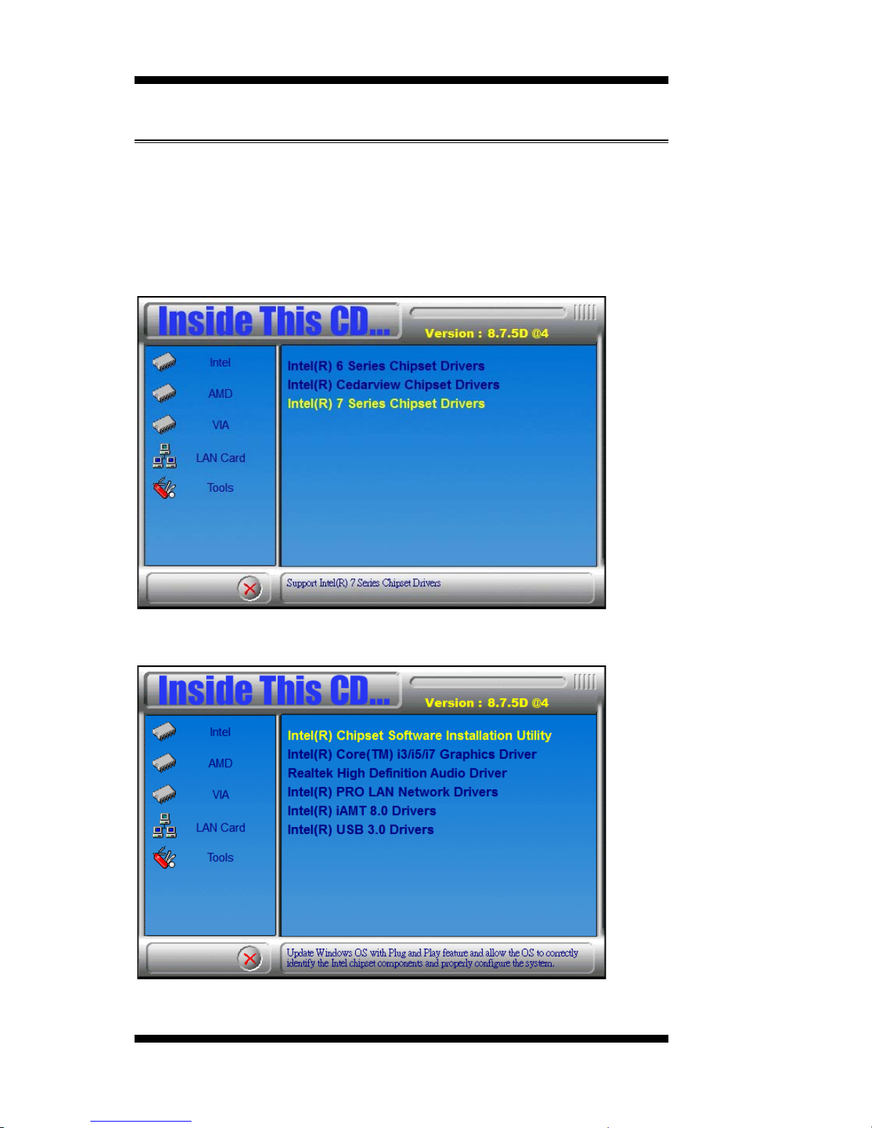
The Int el Chipset Drivers s hou ld be installed first before the software
drivers to enable Plug & Play INF support for I nt el chipset components.
Follow the instru ction s below to c omplete th e insta llation .
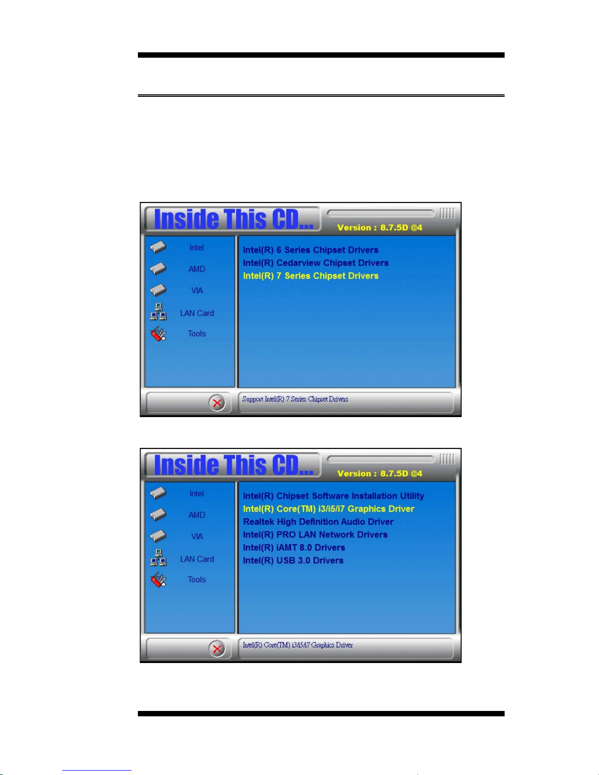
1. Insert the CD that comes with the board. Click Intel and then Intel(R)
7 Series Ch ipset Drivers.
2. Click Intel(R) Chipset Software Installation Utility.
Page 55
DRIVERS INSTALLATION
IB970 User’s Manual 51
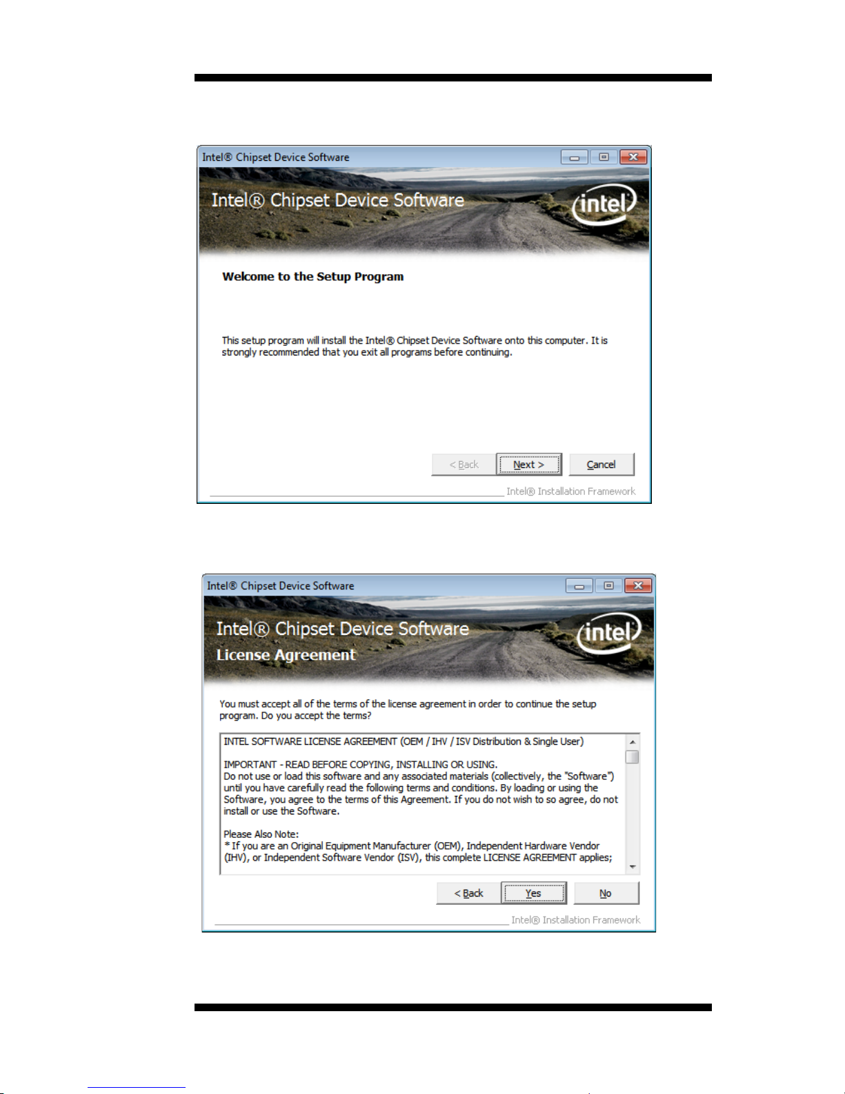
3. When the Welcome screen to the Intel® Chipset Device Software
appears, click Next to cont inu e .
4. C lick Yes t o accept the so ftware license agreement and proceed with
the installation process.
Page 56
DRIVER INSTALLATION
52
IB970 User’s Manual
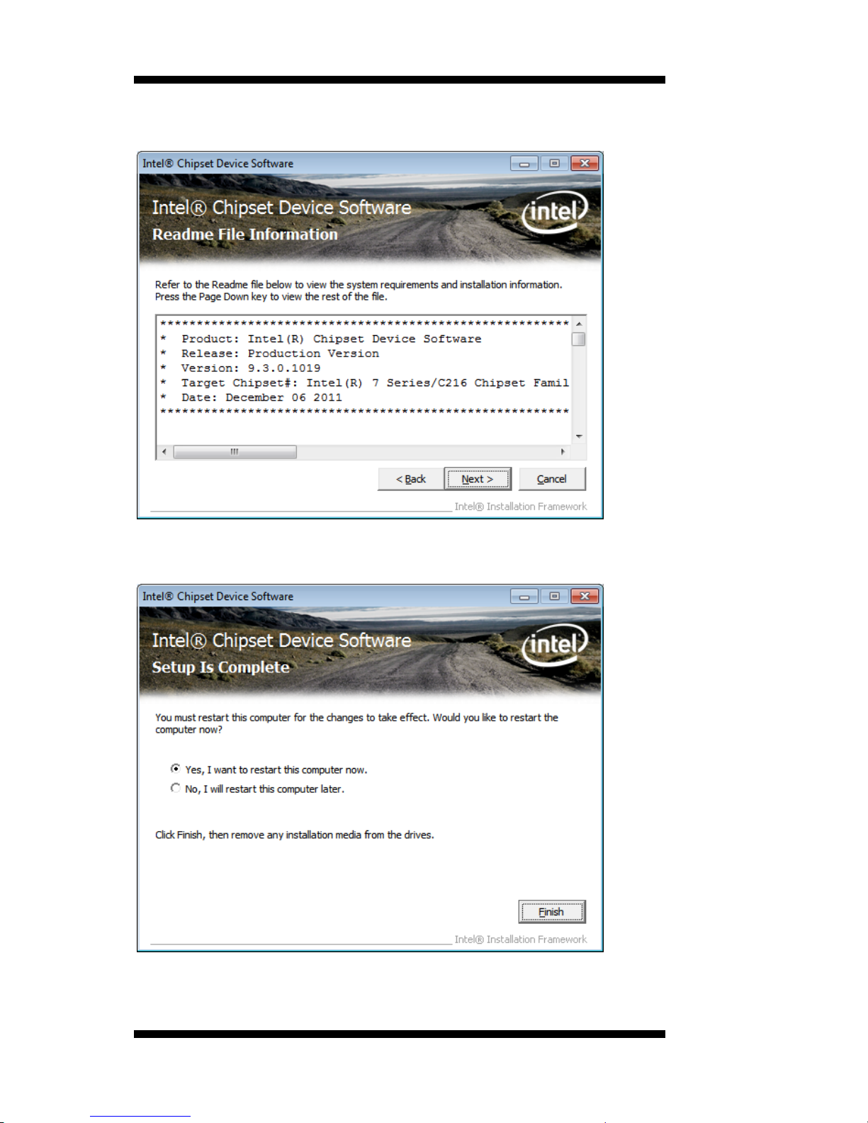
5. On the Readme File Information screen, click Next to c ontinue the
installation.
6. The Setu p process is now complete. Click Finish to restart the
computer and for changes to take effect.
Page 57
DRIVERS INSTALLATION
IB970 User’s Manual 53
VGA Drive rs In s ta llation
NOTE: Before installing the Intel(R) Q77 Chipset Family Graphics
Driver, the Microsoft .NET Framework 3.5 SPI should be first
installed.
To insta ll the VGA drivers, follow the steps below .
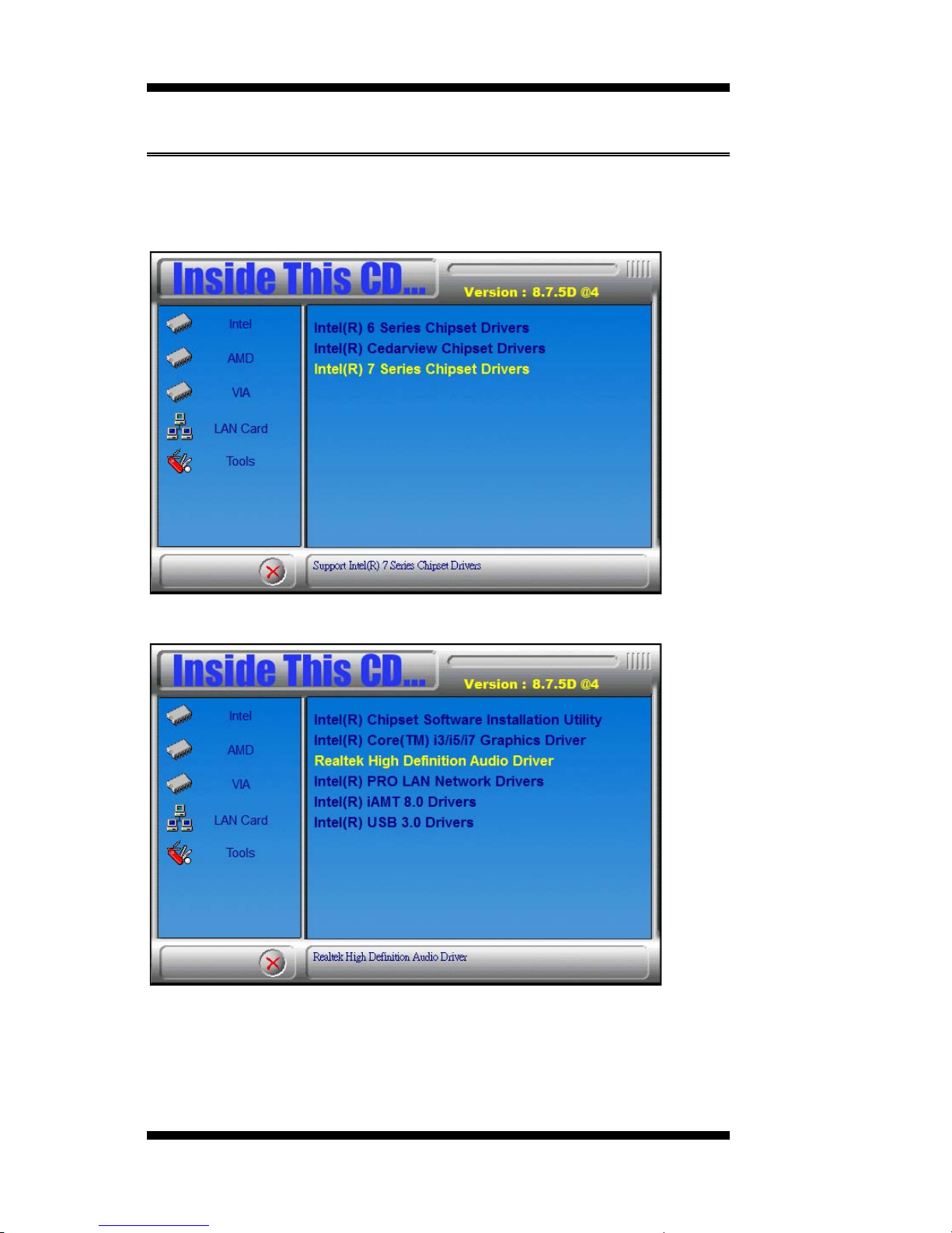
1. Insert the CD that comes with the board. Click Intel and then Intel(R)
Q7 Series C h i p set Drivers.
2. Click Intel(R) Q77 Chipset Family Graphics Driver.
Page 58
DRIVER INSTALLATION
54
IB970 User’s Manual
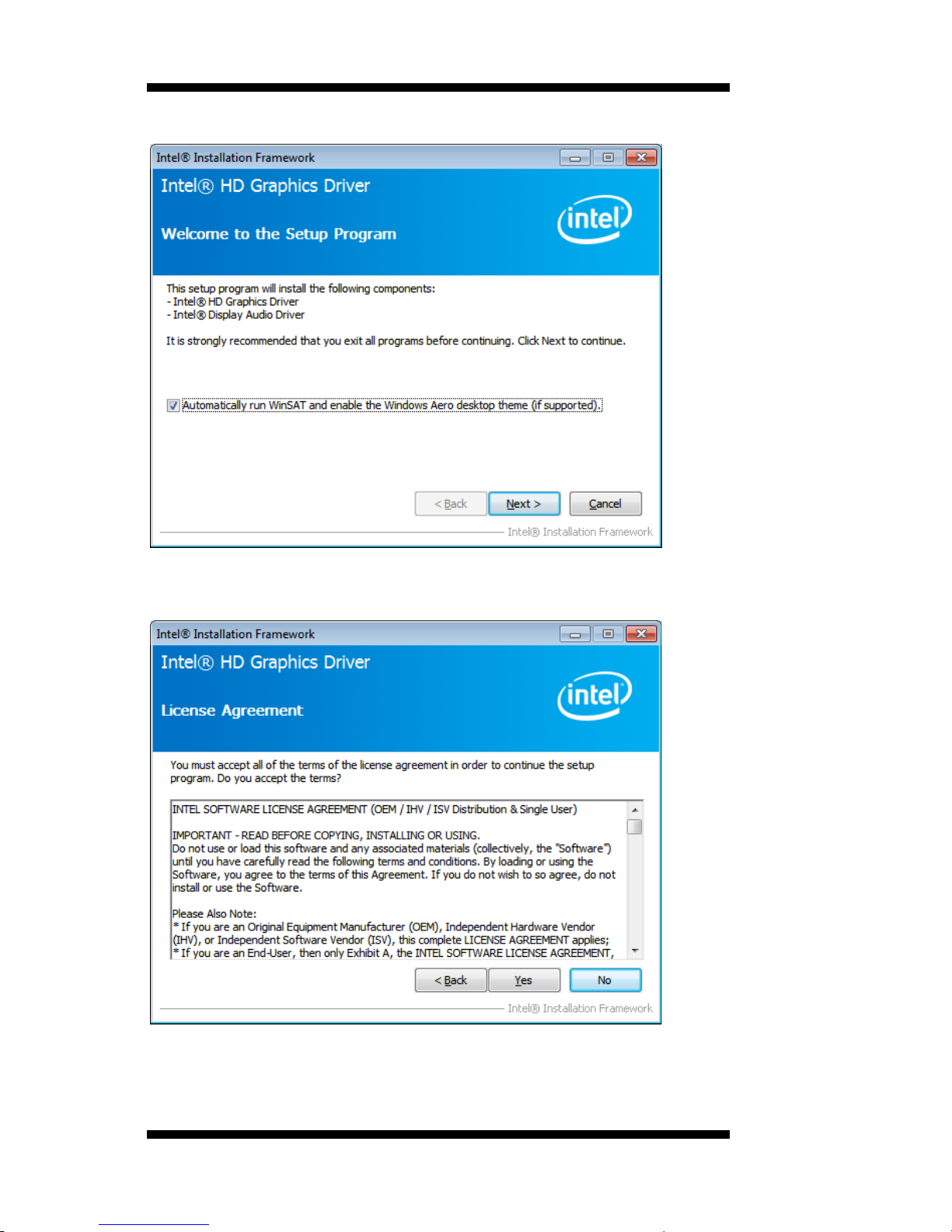
3. When the Welco me screen appears, click Next to continue.
4. Click Yes to to agree with the license agreement and continue the
installation.
Page 59
DRIVERS INSTALLATION
IB970 User’s Manual 55
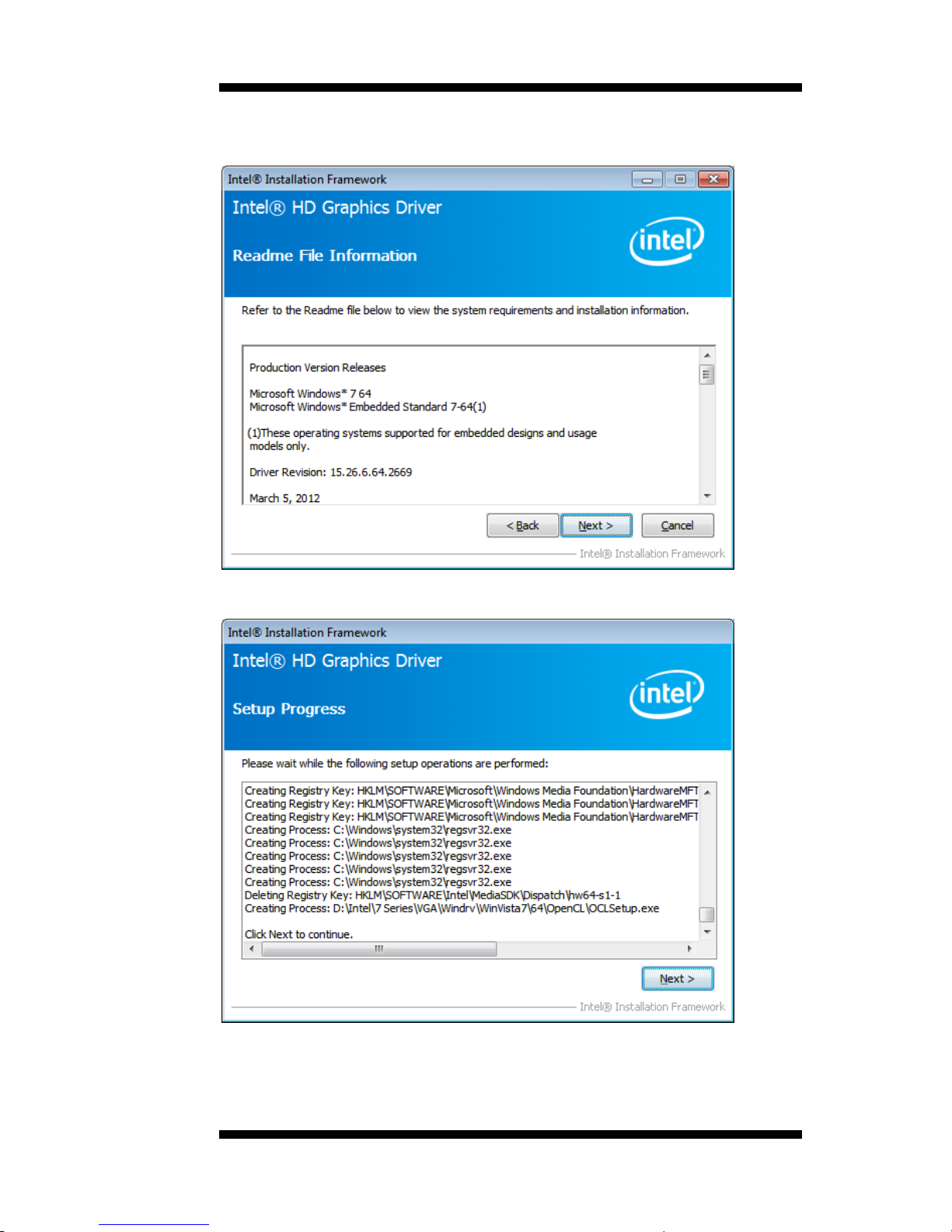
5. On the Readme File Information screen, click Next to c ontinue the
installation o f the Int el® Graphics Media Accelerator Driver.
6. On S etup Progress screen, click Next to continue.
7. Setup complete. Click Finish to restart the c omputer and for changes
to take effect.
Page 60
DRIVER INSTALLATION
56
IB970 User’s Manual
Realtek HD Audio Driver Installation
Follow the steps below to insta ll the Realtek HD Aud io Drivers.
1. Insert the CD that comes with the board. Click Intel and then Intel(R)
Q7 Series C h i p set Drivers.
2. Click Realtek High Definition Audio Driver.
Page 61
DRIVERS INSTALLATION
IB970 User’s Manual 57
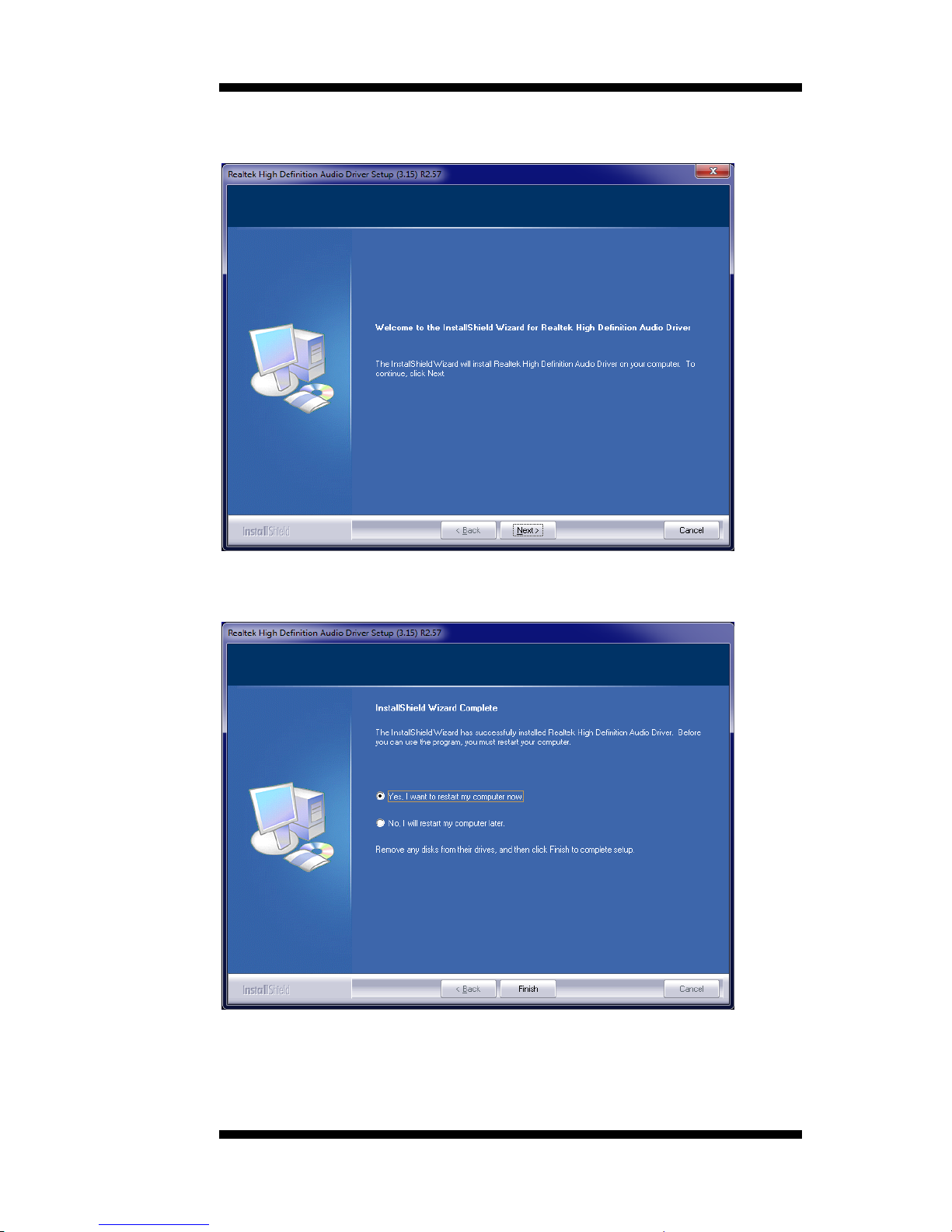
3. On the Welcome to the InstallShield Wizard screen, click Next to
proceed with and complete the installation process.
4. T he I nstallShield W izar d Comp lete. Clic k Finish to restart the
computer and for changes to take effect.
Page 62
DRIVER INSTALLATION
58
IB970 User’s Manual
LAN Drivers I n sta lla tion
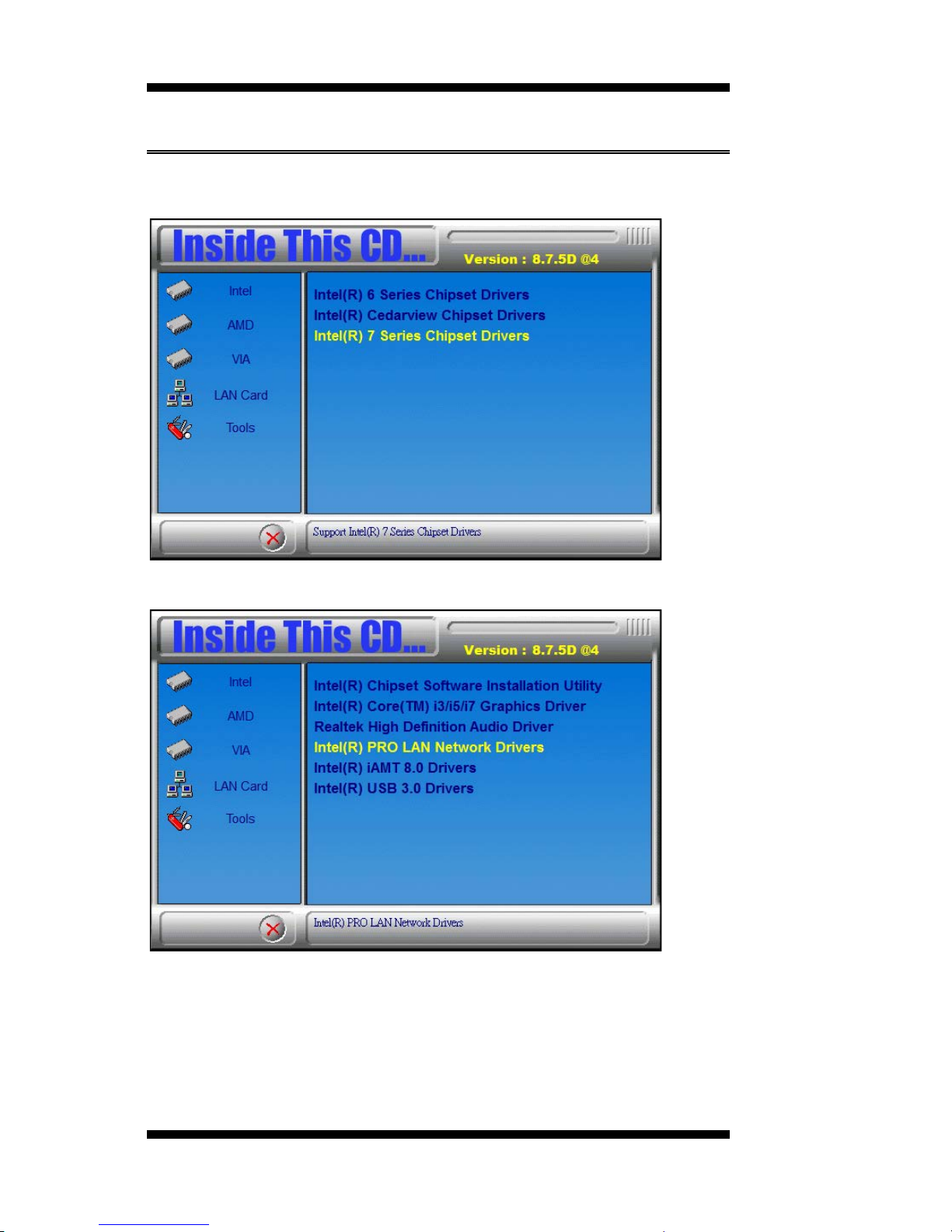
1. Insert the CD that comes with the board. Click Intel and then Intel(R)
Q7 Series C h i p set Drivers.
2. Click Inte l (R) PRO LAN Netwo rk Dri v er.
Page 63
DRIVERS INSTALLATION
IB970 User’s Manual 59
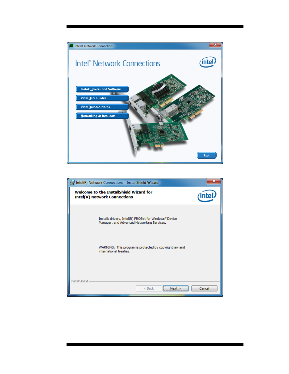
3. Click Insta l l Drivers an d S o ftware.
4. When the Welcome screen appears, click Next.
Page 64
DRIVER INSTALLATION
60
IB970 User’s Manual
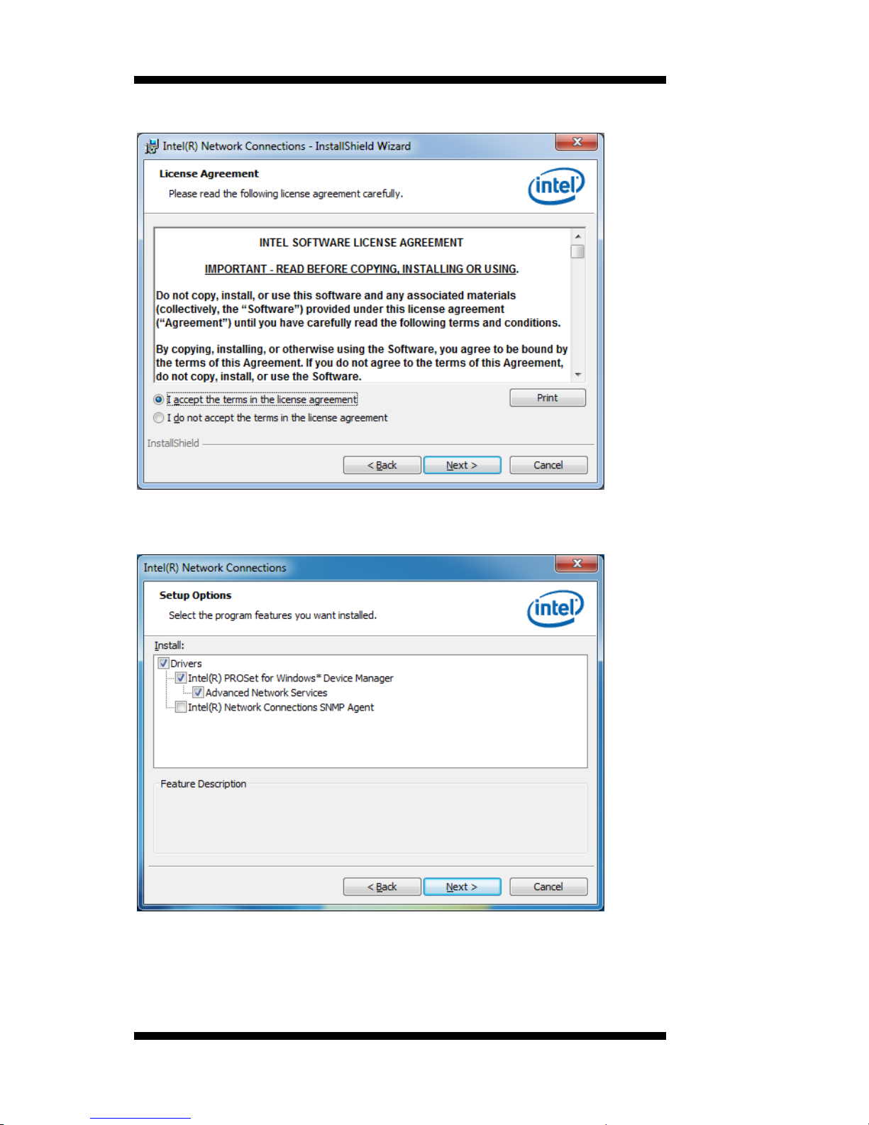
5. Click Next to to agree with the license agreement.
6. Cli ck the checkbox f or Drivers in the Setup Options screen to select it
and click Next to continue.
Page 65
DRIVERS INSTALLATION
IB970 User’s Manual 61
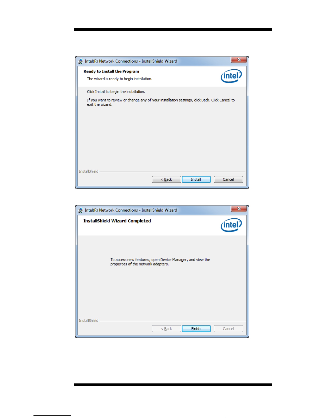
7. The wizard is ready to begin installat ion. C lick Install to begin the
installation.
8. When I nstallShield W izar d is comple te, c lick Finish.
Page 66
DRIVER INSTALLATION
62
IB970 User’s Manual
Intel® Management Engine Interface
Follow the steps below to install the Intel Management Engine.
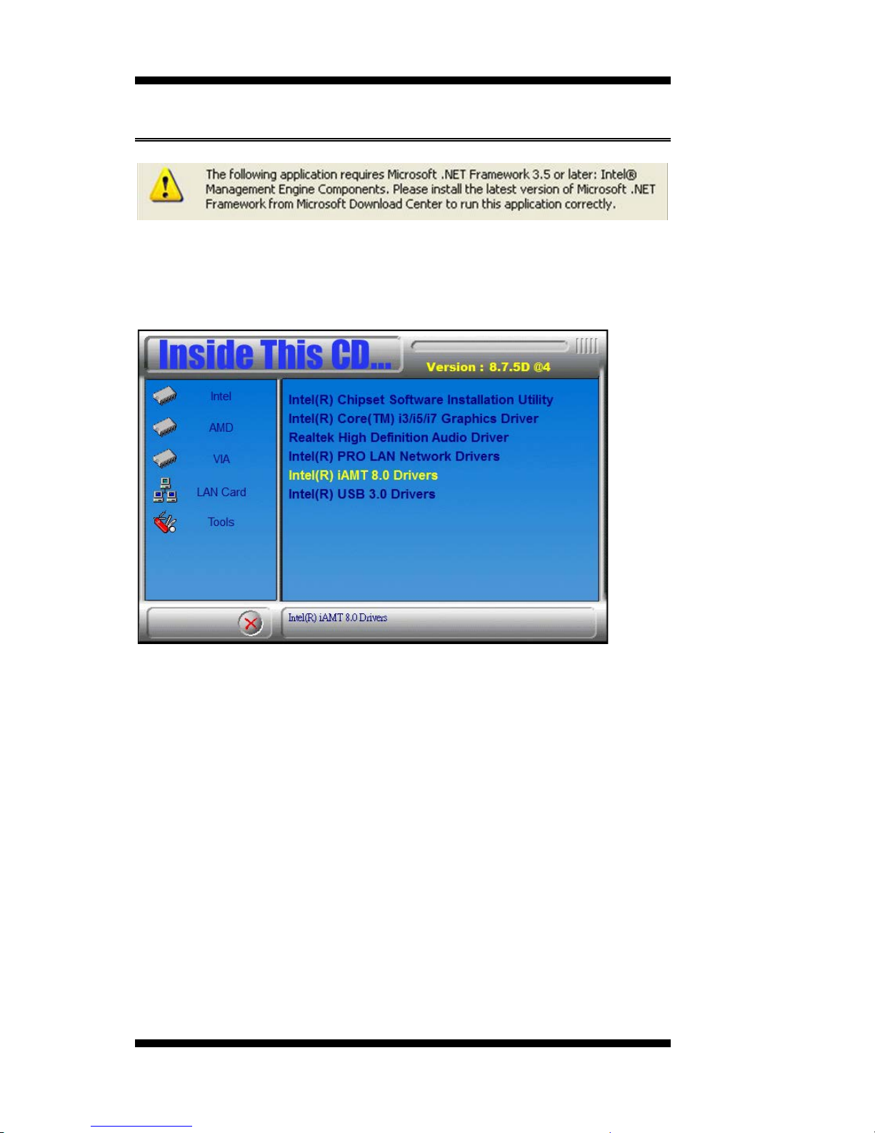
1. Insert the CD that comes with the board. Click Intel and then Intel(R)
AMT 8.0 Drivers.
Page 67
DRIVERS INSTALLATION
IB970 User’s Manual 63
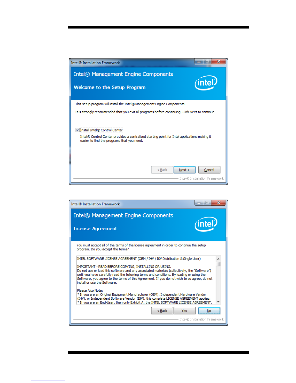
2. When the Welcome screen to the InstallShield Wizard for Intel®
Management Engine Co mp onents, click t he checkbox for Insta ll Intel®
Control Center & click Next.
3. Click Yes to to ag r ee with the license agreement.
Page 68
DRIVER INSTALLATION
64
IB970 User’s Manual
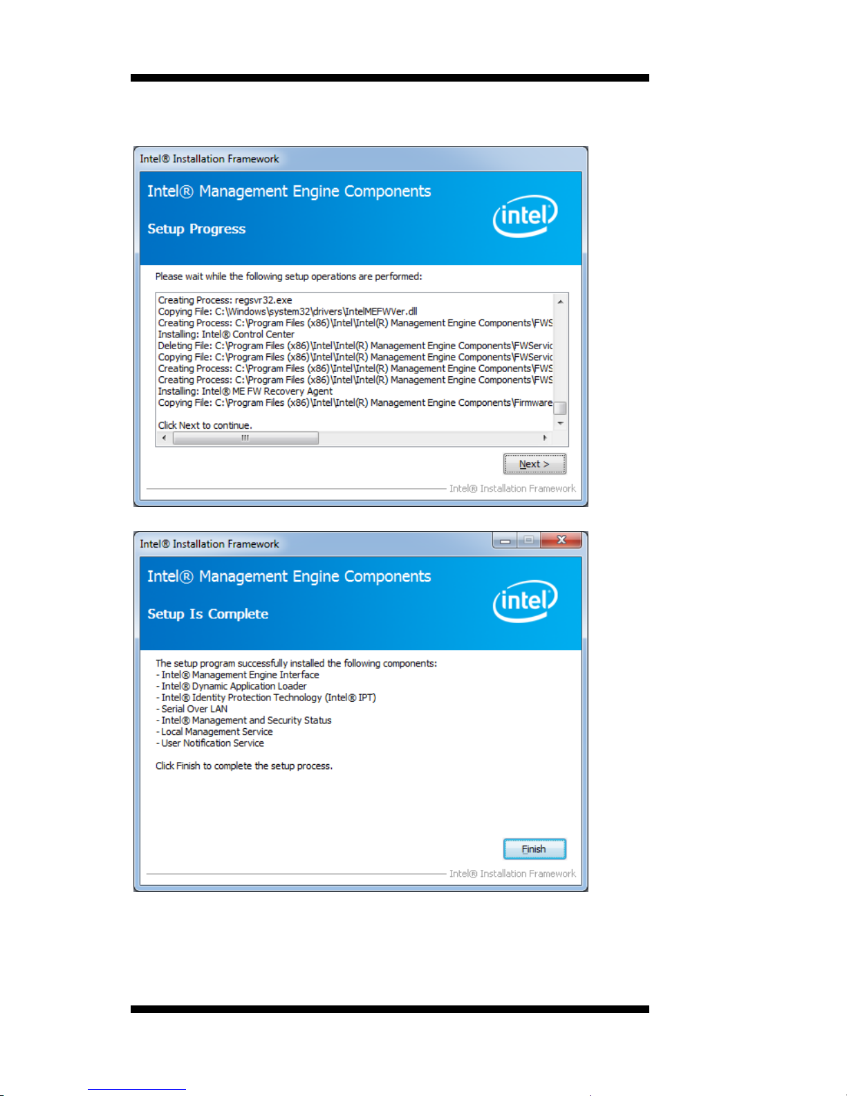
4. When the Setup Progress screen appears, click Next. Then, click
Finish when the setup progr ess has been successfully installed.
Page 69
DRIVERS INSTALLATION
IB970 User’s Manual 65
Intel® USB 3. 0 D rivers
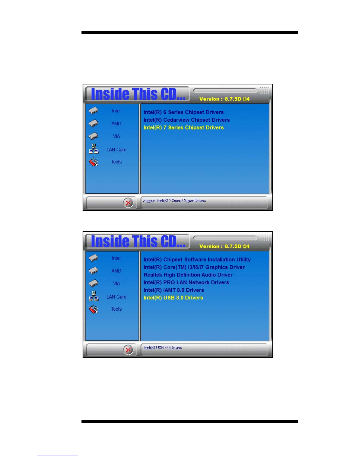
1. Insert the CD that comes with the board. Click Intel and then Intel(R)
Q7 Series C h i p set Drivers.
2. Click Inte l (R) USB 3 .0 Drive rs.
Page 70
DRIVER INSTALLATION
66
IB970 User’s Manual
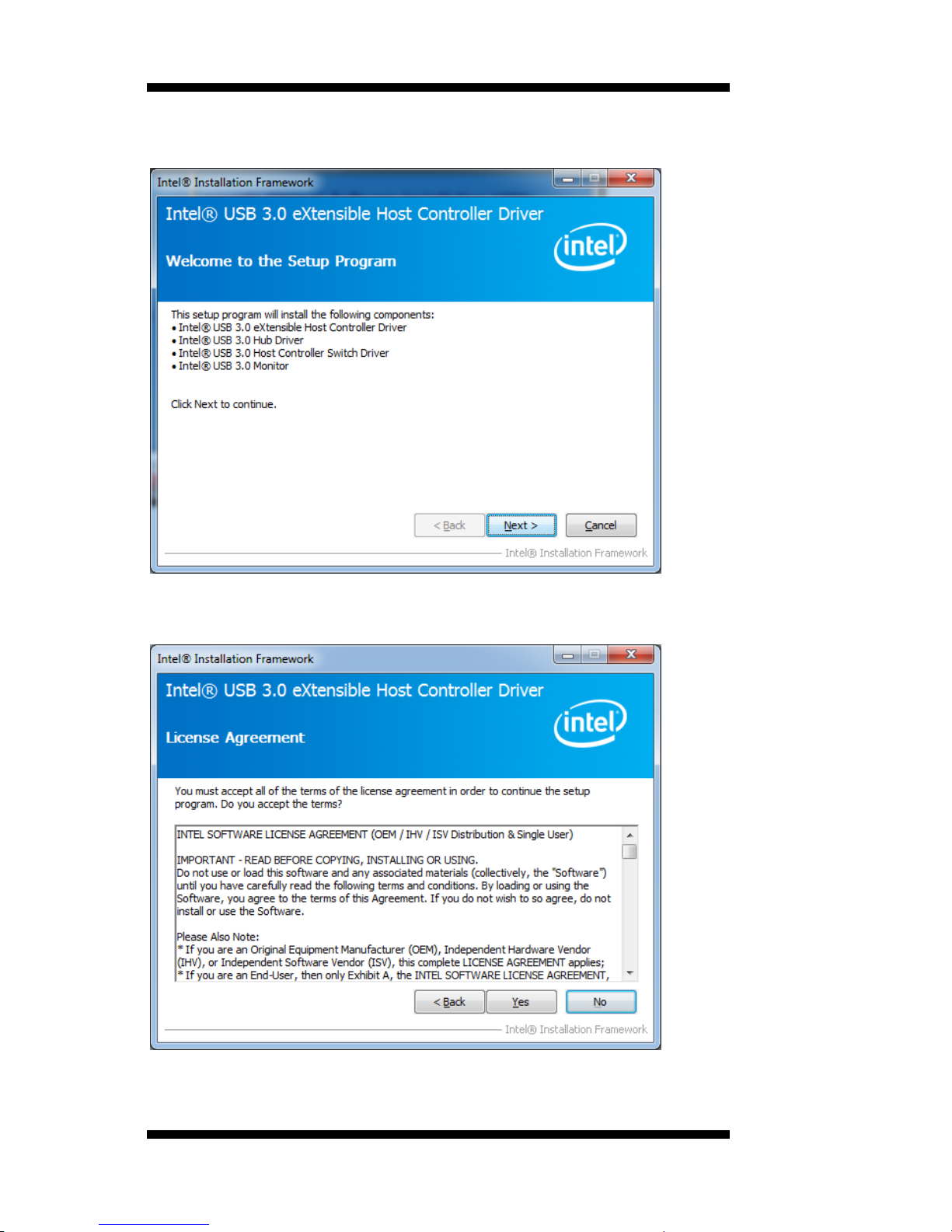
3. When the Welcome screen to t he InstallShield Wizard for Int el® USB
3.0 e Xtens ible Host Controller D riv er, click Next.
4. Click Yes to to ag r ee with the license agreement and continue the
installation.
Page 71
DRIVERS INSTALLATION
IB970 User’s Manual 67
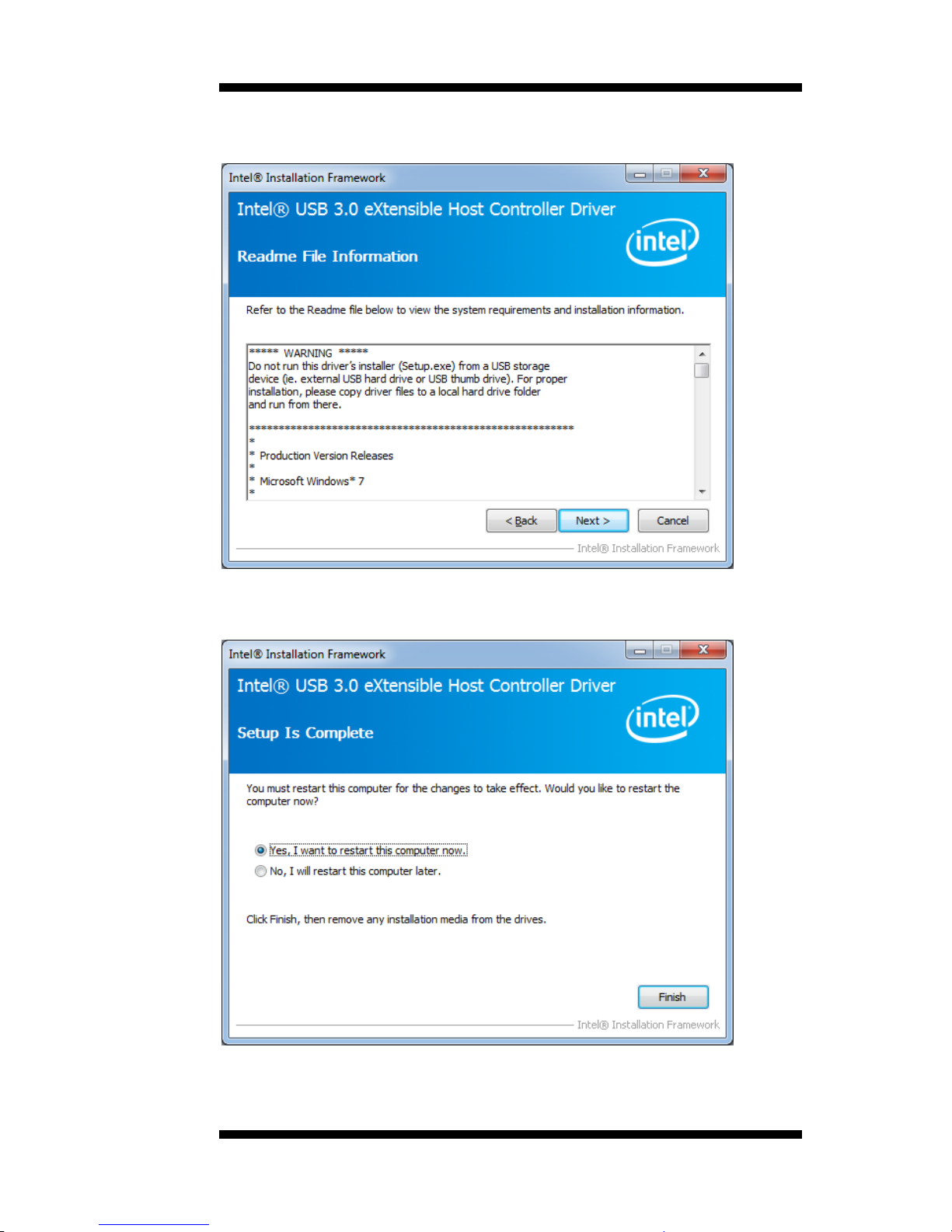
5. On the Readme File Information screen, click Next to c ontinue the
installation o f the Int el® USB 3.0 eXtensible Host Controller Driver .
6. Setup complete. Click Finish to restart the computer and for changes
to take effect.
Page 72

DRIVER INSTALLATION
68
IB970 User’s Manual
This pa ge is intentionally le f t blank .
Page 73

APPENDIX
IB970 User’s Manual 69
Appendix
A. I/O Port Address Map
Each peripheral device in the system is assigned a set of I/O port
addresses which also becomes the identity of the device. The following
t able lis ts the I/O port a d d r e sses u se d.
Address
Device Description
000h - 01Fh
DMA C ontroller # 1
020h - 03Fh
Interrupt Controller #1
040h - 05Fh
Timer
060h - 06Fh
Keyboard Cont r oller
070h - 07Fh
Real Time C lock, NMI
080h - 09Fh
DMA Page Register
0A0h - 0BFh
Interrupt Controller #2
0C0h - 0DFh
DMA C ontroller # 2
0F0h
Clear Math Coprocesso r Busy Signal
0F1h
Reset Math Copr ocessor
1F0h - 1F7h
IDE Inter face
2F8h - 2FFh
Serial Port #2(COM2)
2B0h- 2DFh
Graphics adapter Controller
360h - 36Fh
Networ k Port s
3F8h - 3FFh
Serial Port #1(COM1)
Page 74
APPENDIX
70
IB970 User’s Manual
B. Interrupt Request Lines (IRQ)
Peripheral dev ices us e in terrupt request li nes to notif y CPU f or the service
required. The following table shows the IRQ used by the devices on
board.
Level
Function
IRQ0
Syste m Timer Output
IRQ1
Keyboard
IRQ3
Serial Port #2
IRQ4
Serial Port #1
IRQ8
Real Time C lock
IRQ14
Primary IDE
IRQ15
Secondary IDE
Page 75

APPENDIX
IB970 User’s Manual 71
C. Watchdog Timer Configuration
The WDT is used to generate a variety of output signals after a user
progr ammable co u nt . The WDT is suitable fo r use in the prevention of
sys tem lo ck-up, such as when software becomes trapped in a deadlock.
Under these sorts of circumstances, the t imer will count to zero and the
selected output s will be driven. Under normal circumstance, t he user w ill
restart the WDT at r eg ular intervals befor e the timer counts to zer o.
SAMPLE CODE:
//--------------------------------------------------------------------------//
// THIS CODE AND INFORMATION IS PROVIDED "AS IS" WITHOUT WARRANTY OF ANY
// KIND, EITHER EXPRESSED OR IMPLIED, INCLUDING BUT NOT LIMITED TO THE
// IMPLIED WARRANTIES OF MERCHANTABILITY AND/OR FITNESS FOR A PARTICULAR
// PURPOSE.
//
//--------------------------------------------------------------------------#include <dos.h>
#include <conio.h>
#include <stdio.h>
#include <stdlib.h>
#include "F81866. H "
//--------------------------------------------------------------------------int main (int argc, char *argv[]);
void EnableWDT(int);
void DisableWDT(void);
//--------------------------------------------------------------------------int main (int argc, char *argv[])
{
unsigned char bBuf;
unsigned char bTime;
char **endptr;
char SIO;
printf("Fintek 81866 watch dog program\n");
SIO = Init_F81866();
if (SIO == 0)
{
printf("Can not detect Fintek 81866, program abort.\n");
return(1);
}//if (SIO == 0)
if (argc != 2)
{
printf(" Parameter incorrect!!\n");
return (1);
}
bTime = strtol (argv[1], endptr, 10);
printf("System will reset after %d seconds\n", bTime);
if (bTime)
{ EnableWDT(bTime); }
else
{ DisableWDT(); }
return 0;
Page 76

APPENDIX
72
IB970 User’s Manual
}
//--------------------------------------------------------------------------void EnableWDT(int interval)
{
unsigned char bBuf;
bBuf = Get_F81866_Reg(0x2B);
bBuf &= (~0x20);
Set_F81866_Reg(0x2B, bBuf); //Enable WDTO
Set_F81866_LD(0x07); //switch to logic device 7
Set_F81866_Reg(0x30, 0x01); //enab le timer
bBuf = Get_F81866_Reg(0xF5);
bBuf &= (~0x0F);
bBuf |= 0x52;
Set_F81866_Reg(0xF5, bBuf); //count mode is second
Set_F81866_Reg(0xF6, interval); //set timer
bBuf = Get_F81866_Reg(0xFA);
bBuf |= 0x01;
Set_F81866_Reg(0xFA, bBuf); //enable WDTO output
bBuf = Get_F81866_Reg(0xF5);
bBuf |= 0x20;
Set_F81866_Reg(0xF5, bBuf); //start counting
}
//--------------------------------------------------------------------------void DisableWDT(void)
{
unsigned char bBuf;
Set_F81866_LD(0x07); //switch to logic device 7
bBuf = Get_F81866_Reg(0xFA);
bBuf &= ~0x01;
Set_F81866_Reg(0xFA, bBuf); //disable WDTO output
bBuf = Get_F81866_Reg(0xF5);
bBuf &= ~0x20;
bBuf |= 0x40;
Set_F81866_Reg(0xF5, bBuf); //disable WDT
}
//---------------------------------------------------------------------------
Page 77

APPENDIX
IB970 User’s Manual 73
//--------------------------------------------------------------------------//
// THIS CODE AND INFORMATION IS PROVIDED "AS IS" WITHOUT WARRANTY OF ANY
// KIND, EITHER EXPRESSED OR IMPLIED, INCLUDING BUT NOT LIMITED TO THE
// IMPLIED WARRANTIES OF MERCHANTABILITY AND/OR FITNESS FOR A PARTICULAR
// PURPOSE.
//
//--------------------------------------------------------------------------#include "F81866. H "
#include <dos.h>
//--------------------------------------------------------------------------unsigned int F81866_BASE;
void Unlock_F81866 (void);
void Lock_F81866 (void);
//--------------------------------------------------------------------------unsigned int Init_F81866(void)
{
unsigned int result;
unsigned char ucDid;
F81866_BASE = 0x4E;
result = F81866_BASE;
ucDid = Get_F81866_Reg(0x20);
if (ucDid == 0x07) //Fintek 81866
{ goto Init_Finish; }
F81866_BASE = 0x2E;
result = F81866_BASE;
ucDid = Get_F81866_Reg(0x20);
if (ucDid == 0x07) //Fintek 81866
{ goto Init_Finish; }
F81866_BASE = 0x00;
result = F81866_BASE;
Init_Finish:
return (result);
}
//--------------------------------------------------------------------------void Unlock_F81866 (void)
{
outportb(F81866_INDEX_PORT, F 81866_UN LOCK );
outportb(F81866_INDEX_PORT, F 81866_UN LOCK );
}
//--------------------------------------------------------------------------void Lock_F81866 (void)
{
outportb(F81866_INDEX_PORT, F 81866_LOCK);
}
//--------------------------------------------------------------------------void Set_F81866_LD( unsigned char LD)
{
Unlock_F81866();
outportb(F81866_INDEX_PORT, F 81866_REG_LD);
outportb(F81866_DATA_PORT, LD);
Lock_F81866();
}
//--------------------------------------------------------------------------void Set_F81866_Reg( unsigned char REG, unsigned char DATA)
{
Unlock_F81866();
outportb(F81866_INDEX_PORT, REG);
outportb(F81866_DATA_POR T, DATA) ;
Lock_F81866();
}
//---------------------------------------------------------------------------
Page 78

APPENDIX
74
IB970 User’s Manual
unsigned char Get_F81866_Reg(unsigned char REG)
{
unsigned char Result;
Unlock_F81866();
outportb(F81866_INDEX_PORT, REG);
Result = inportb(F81866_DATA_PORT);
Lock_F81866();
return Result;
}
//---------------------------------------------------------------------------
//--------------------------------------------------------------------------//
// THIS CODE AND INFORMATION IS PROVIDED "AS IS" WITHOUT WARRANTY OF ANY
// KIND, EITHER EXPRESSED OR IMPLIED, INCLUDING BUT NOT LIMITED TO THE
// IMPLIED WARRANTIES OF MERCHANTABILITY AND/OR FITNESS FOR A PARTICULAR
// PURPOSE.
//
//--------------------------------------------------------------------------#ifndef __F81866_H
#define __F81866_H 1
//--------------------------------------------------------------------------#define F81866_INDEX_PORT (F81866_BASE)
#define F81866_DATA_PORT (F81866_BASE+1)
//--------------------------------------------------------------------------#define F81866_REG_LD 0x07
//--------------------------------------------------------------------------#define F81866_UNLOCK 0x87
#define F81866_LOCK 0xAA
//--------------------------------------------------------------------------unsigned int Init_F81866(void);
void Set_F81866_LD( unsigned char);
void Set_F81866_Reg( unsigned char, unsigned char);
unsigned char Get_F81866_Reg( unsigned char);
//--------------------------------------------------------------------------#endif //__F81866_H
Page 79

Mouser Electronics
Authorized Distributor
Click to View Pricing, Inventory, Delivery & Lifecycle Information:
IBASE:
SBC-IB970 SBC-IB970F SBC-IB970RF IB970RF
 Loading...