

Mouser EmCORE-i9457 User Manual

EmCORE-i9457
3.5” Embedded Board
User’s Manual
Version 1.1
2008.08

This page is intentionally left blank.

- i -
Index
Table of Contents
Chapter 1- Introduction .....................................................................1
1.1 Copyright Notice ...............................................2
1.2 About this User’s Manual .................................2
1.3 Warning .............................................................2
1.4 Replacing the lithium battery ..........................3
1.5 Technical Support .............................................3
1.6 Warranty ............................................................4
1.7 Packing List.......................................................5
1.8 Ordering Information ........................................5
1.9 Specications ...................................................6
1.10 Board Dimensions ..........................................7
1.11 Installing the CPU ...........................................9
1.12 Installing the Memory ...................................10
1.13 Heatsink Installation .....................................11
1.14 Heatsink Dimensions ...................................12
Chapter 2- Installation .....................................................................13
2.2 Jumpers and Connectors ..............................15
Jumpers ..................................................................16
JRS2: COM2 RS-232/422/485 Mode Select ..............16
LV3, LV4: COM2 Power source Special Support .....16
JBAT1: Clear CMOS Setup ........................................17
JVLCD1: LCD Panel Voltage Select .......................... 17
Connectors .............................................................18
INV1: LCD Inverter Connector ..................................18
SATA1: Serial ATA Connector ...................................18
LPT1: Parallel Port or FDD Connector .....................19
JFRT1: Switches ........................................................20
IDE1: Primary IDE Connector ................................... 21
USB2/ USB3: USB Connectors .................................22
JSMB1: External SMBUS Connector .......................22
JCOM2: RS-422/ 485 Output Connector .................. 22
COM2: RS-232 Connector .........................................23
AUDIO1: Front Panel AUDIO Connector .................. 23

- ii -
Index
MINIPCI1: MiniPCI slot ..............................................23
USB1: USB Connector ..............................................24
LAN1: RJ-45 connector .............................................24
KBM1: Keyboard & Mouse ........................................24
VGA1: CRT Connector ..............................................25
COM1: RS232 Connector .......................................... 25
ATX1: ATX Power Supply Connector ....................... 26
CPUF1: CPU Fan Power Connector .........................26
LVDS1: LVDS LCD Connector ...................................27
CFD1: Compact Flash II Socket ................................ 28
2.3 The Installation Paths of CD Driver ...............29
Chapter 3- BIOS ...............................................................................31
3.1 BIOS Introduction ...........................................32
3.2 BIOS Setup ......................................................32
3.3 Standard CMOS Features ..............................33
3.4 Advance BIOS Features .................................36
3.5 Advanced Chipset Features ..........................39
3.6 Integrated Peripherals ...........................................41
3.7 Power Management Setup .............................44
3.8 PNP/PCI Congurations .................................46
3.9 PC Health Status .............................................48
3.10 Load Optimized Defaults .............................49
3.11 Set Password ...............................................50
3.12 Save & Exit Setup .........................................51
3.13 Exit Without Saving ......................................52
3.14 BIOS Beep Sound code list .........................53
3.15 BIOS memory mapping ................................53
3.16 Award BIOS Post Codes ..............................54
Chapter 4- Appendix .......................................................................59
4.1 I/O Port Address Map .....................................60
4.2 Interrupt Request Lines (IRQ) ........................62
4.3 Memory Resources.........................................63

- 1 -
Introduction
1Chapter 1
Introduction
Chapter 1- Introduction

- 2 -
Introduction
1.1 Copyright Notice
All Rights Reserved.
The information in this document is subject to change without prior notice in
order to improve the reliability, design and function. It does not represent a
commitment on the part of the manufacturer.
Under no circumstances will the manufacturer be liable for any direct, indirect, special, incidental, or consequential damages arising from the use or inability to use the product or documentation, even if advised of the possibility
of such damages.
This document contains proprietary information protected by copyright. All
rights are reserved. No part of this manual may be reproduced by any mechanical, electronic, or other means in any form without prior written permission of the manufacturer.
1.2 About this User’s Manual
This User’s Manual is intended for experienced users and integrators with
hardware knowledge of personal computers. If you are not sure about any
description in this User’s Manual, please consult your vendor before further
handling.
1.3 Warning
Single Board Computers and their components contain very delicate
Integrated Circuits (IC). To protect the Single Board Computer and its
components against damage from static electricity, you should always follow
the following precautions when handling it :
Disconnect your Single Board Computer from the power source when you
want to work on the inside.
Hold the board by the edges and try not to touch the IC chips, leads or
circuitry.
Use a grounded wrist strap when handling computer components.
Place components on a grounded antistatic pad or on the bag that came
with the Single Board Computer, whenever components are separated
from the system.
1.
2.
3.
4.

- 3 -
Introduction
1.4 Replacing the lithium battery
Incorrect replacement of the lithium battery may lead to a risk of explosion.
The lithium battery must be replaced with an identical battery or a battery
type recommended by the manufacturer.
Do not throw lithium batteries into the trashcan. It must be disposed of in
accordance with local regulations concerning special waste.
1.5 Technical Support
If you have any technical difculties, please consult the user’s manual rst
at:
ftp://ftp.arbor.com.tw/pub/manual
Please do not hesitate to call or e-mail our customer service when you still
can not nd out the answer.
http://www.arbor.com.tw
E-mail:info@arbor.com.tw

- 4 -
Introduction
1.6 Warranty
This product is warranted to be in good working order for a period of two
years from the date of purchase. Should this product fail to be in good
working order at any time during this period, we will, at our option, replace
or repair it at no additional charge except as set forth in the following terms.
This warranty does not apply to products damaged by misuse, modications,
accident or disaster.
Vendor assumes no liability for any damages, lost prots, lost savings or any
other incidental or consequential damage resulting from the use, misuse of,
or inability to use this product. Vendor will not be liable for any claim made
by any other related party.
Vendors disclaim all other warranties, either expressed or implied, including
but not limited to implied warranties of merchantibility and tness for a particular purpose, with respect to the hardware, the accompanying product’s
manual(s) and written materials, and any accompanying hardware. This
limited warranty gives you specic legal rights.
Return authorization must be obtained from the vendor before returned
merchandise will be accepted. Authorization can be obtained by calling or
faxing the vendor and requesting a Return Merchandise Authorization (RMA)
number. Returned goods should always be accompanied by a clear problem
description.
- 5 -
Introduction
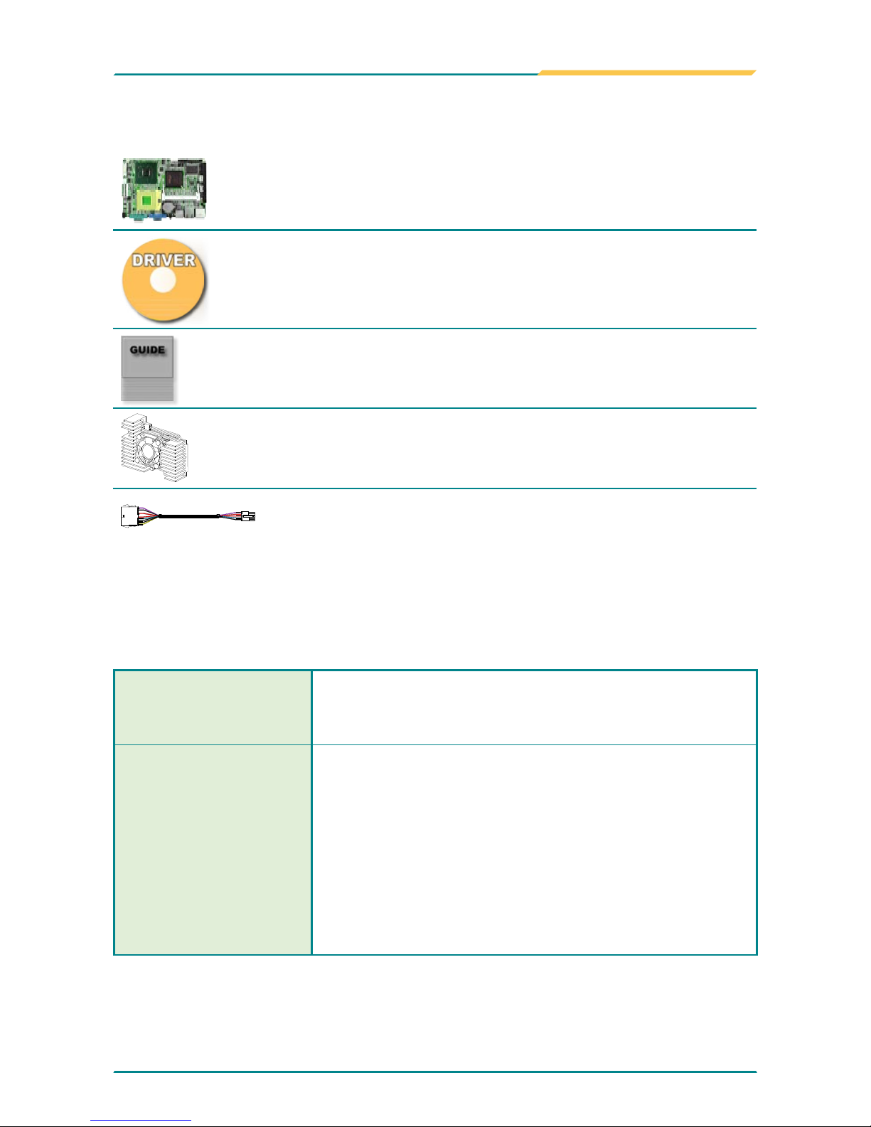
1.7 Packing List
1x EmCORE-i9457 3.5” Embedded Board
1x Driver CD
1x Quick Installation Guide
1 x CPU Cooler
1 x ATX Power cable
ATX main power connector (2x10 pins) to EmCOREi9457 power connector (2x5 pins)
If any of the above items is damaged or missing, contact your vendor
immediately.
1.8 Ordering Information
EmCORE-i9457VLG
3.5” Intel 65nm µFC-PGA Core™ Duo/Core™ 2
Duo/Celeron M (667MHz) Embedded Board with
CRT/LCD, Audio and Gb LAN
Cable kit
CBK-08-9457-00
1 x Audio Cable
1 x COM Port Cable
1 x LPT to FDD Cable
1 x IDE Cable
1 x LPT Cable
1 x Keyboard & mouse Cable
1 x SATA Cable
2 x USB Cable

- 6 -
Introduction
1.9 Specications
Form Factor 3.5” Embedded Board
CPU Supports socket mPGA 478 for Intel® Core™ 2 Duo/
Core™ Duo/ Celeron M (FSB 667MHz)
Chipset Intel® 945GME + Intel® ICH7M
System Memory 1 x 200-pin SO-DIMM socket up to 2GB DDRII
400/533/667 SDRAM
VGA/ LCD Controller Intel® Graphics Media Accelerator (GMA) 950 graphics
core w/ CRT/ Dual Channel LVDS (Dual independent
display)
Ethernet 1 x RTL8111B PCIe 10/100/1000 Base-T Ethernet
I/O Chips WINBOND W83627
BIOS Phoenix-Award PnP Flash BIOS
Audio ALC655 AC’97 Codec, Line-in/out, Mic-in
IDE Interface 1 x IDE (Ultra ATA 33), support 2 IDE devices
SATA 1 x Serial ATA 300MB/s HDD transfer rate
Serial Port 2 x COM port (1 x RS232, 1x RS232/422/485
selectable)
Parallel Port/ Floppy 1 x SPP/EPP/ECP mode
1 x Floppy connector, shared with Parallel Port
KBMS Standard PS/2 Keyboard and Mouse
Universal Serial Bus 6 x USB 2.0 compliant
LCD Dual Channel LVDS
Expansion Interface 1 x CF II socket
1 x MiniPCI socket
Hardware Monitor Chip Integrated in W83627
Operation Temp. -20oC ~ 70oC (-4oF ~ 158oF)
Watchdog Timer 255-level Reset
Dimension (L x W) 146 x 102 mm (5.7” x 4”)
- 7 -
Introduction
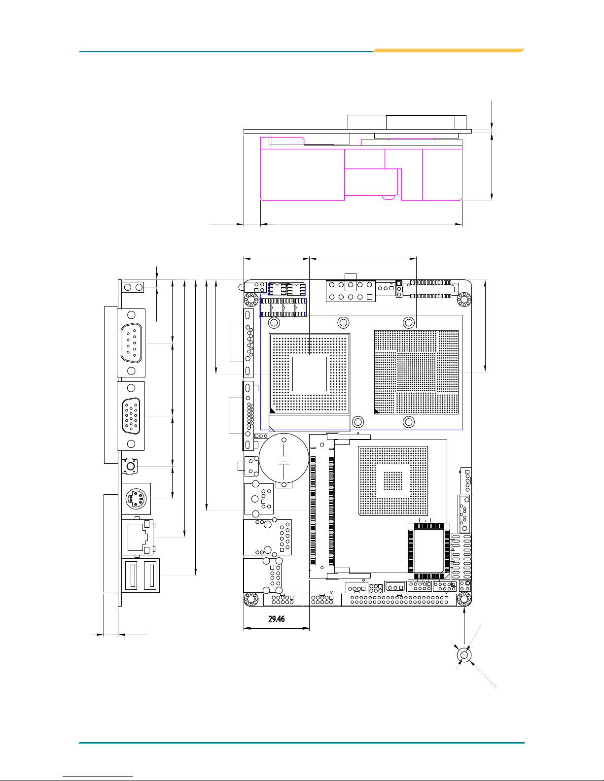
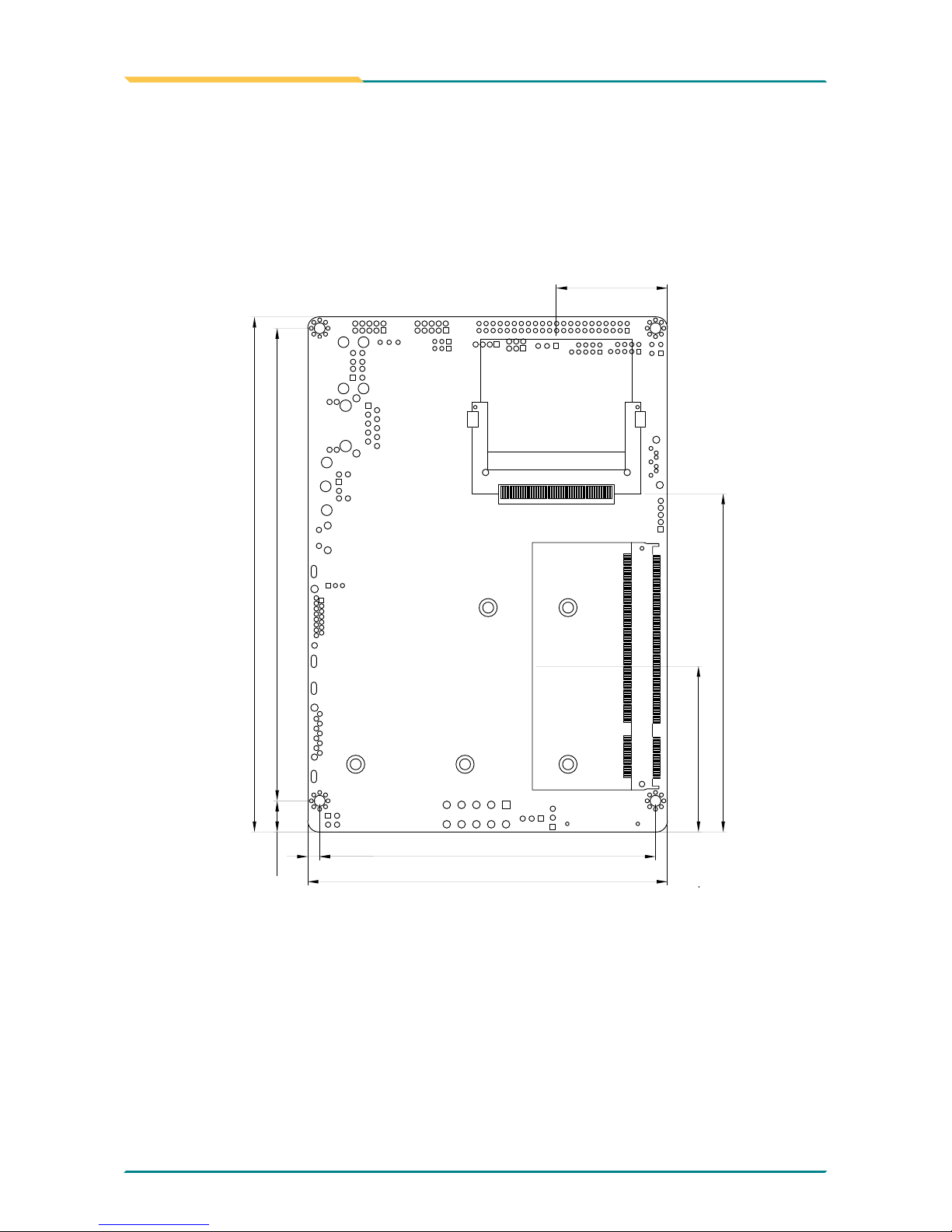
1.10 Board Dimensions
CF
1
+
mPGA478 SOCKET
10 5
5
6
1
1
1
2
1
30.1
6.5
3.35
28.24 32.64 22.48 14.61
115.11
132.27
1.2
67.2
29.47 47.75
42.16
41.28
103.32
29.46
8.84133.93
3.38
95.2
101.96
46.99
95.91
?3.1
?6.35
7.59 90
1.6
Unit: mm
- 8 -
Introduction
+
8.84133.93
3.38
95.2
101.96
146
46.99
95.91
31.47
Unit: mm
- 9 -
Introduction
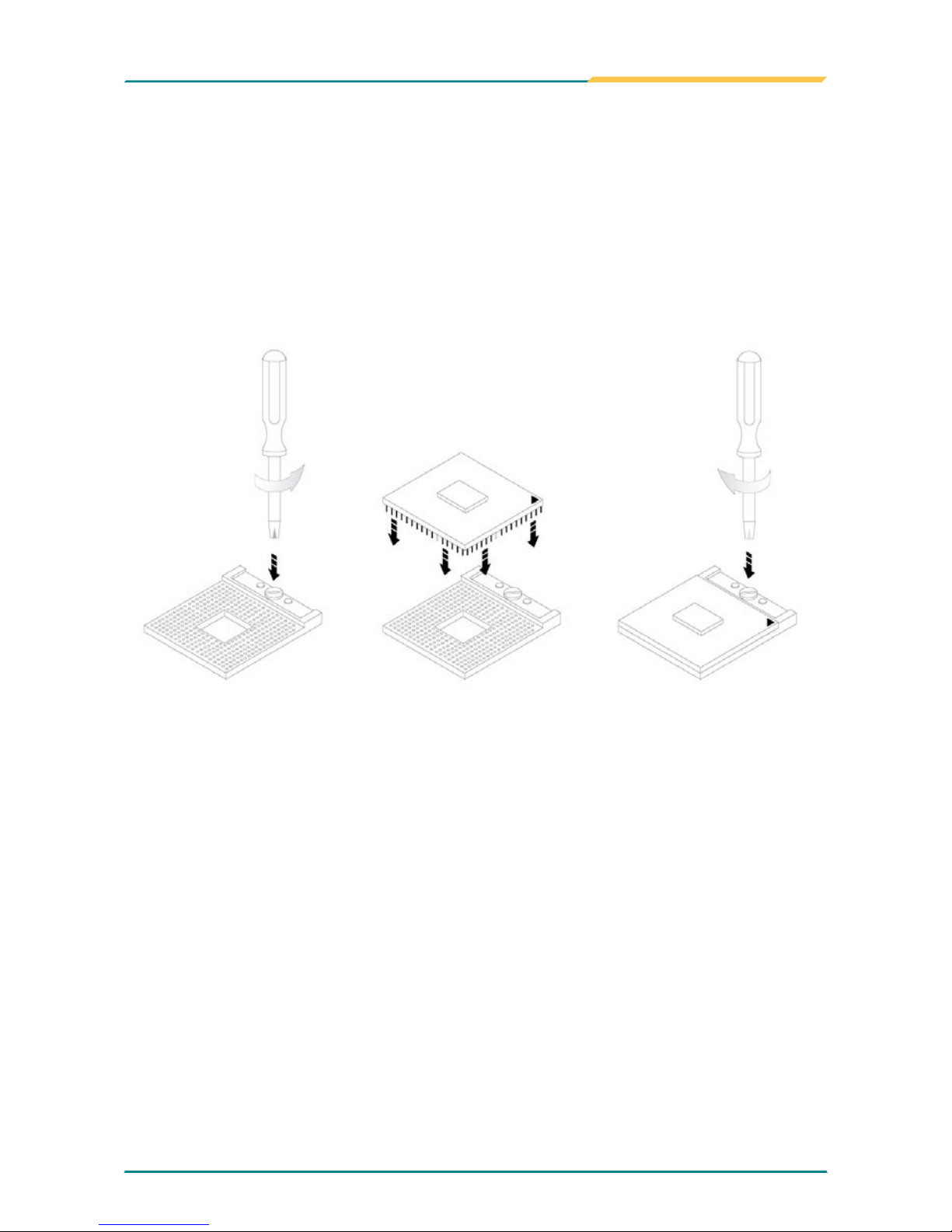
1.11 Installing the CPU
The processor socket comes with a screw to secure the CPU. As showing in
the picture as bellow, loose the screw rst before inserting the CPU.
Place the CPU into the socket by making sure the notch on the corner of the
CPU corresponding with the notch on the inside of the socket. Once the CPU
has slide into the socket, lock the screw.
Make sure that heat sink of the CPU top surface is in complete contact to
avoid the CPU overheating problem.
If not, it would cause your system or CPU to be hanged, unstable, damaged.
- 10 -
Introduction
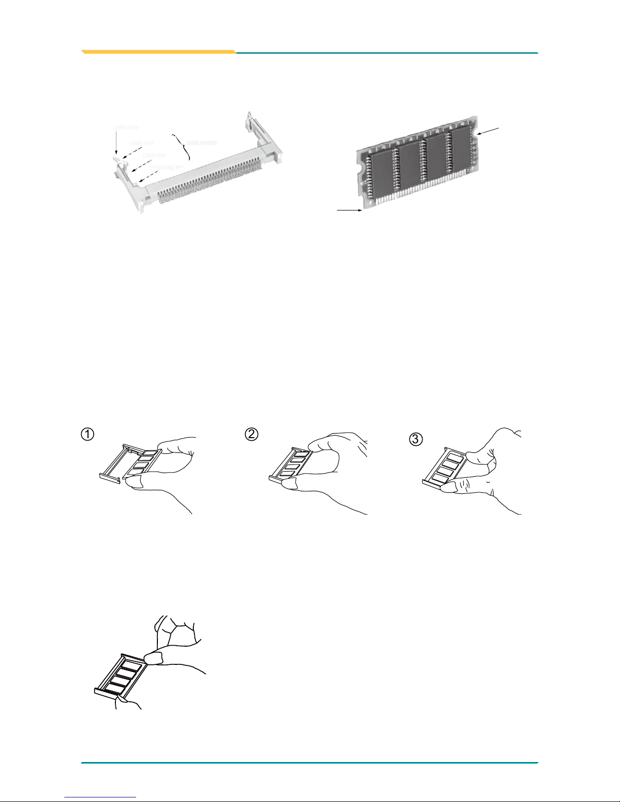
1.12 Installing the Memory
To install the Memory module, locate the Memory SO-DIMM slot on the
board and perform as below:
1. Adjust the socket polarizing key and the board key to the same direction.
2. Insert the board obliquely. Moreover, lay the board in parallel to the
opening at angle of 20o to 30o, and softly insert the board so as to hit the
socket bottom. Stopping insertion halfway will result in improper insertion.
3. Applying the board side notch in parallel to the socket bottom so that
the board position cannot be displaced, press the board side notch up,
and x it to the latch portion at both socket edges. Press the board side
notch, and release the notch with a snap “click” tone, if the printed board
exceeds the latch claw head.
Side notch
Key
Latch knob
Latch claw
Latch section
Latch arm
Polarizing key
1
2
3
Procedures for board extraction
Apply the thumb nail to the latch knob at both socket edges. Forcibly widen
the latch knobs to right and left ways, and release the latch. Then draw the
board out along an angle where the board is raised.
- 11 -
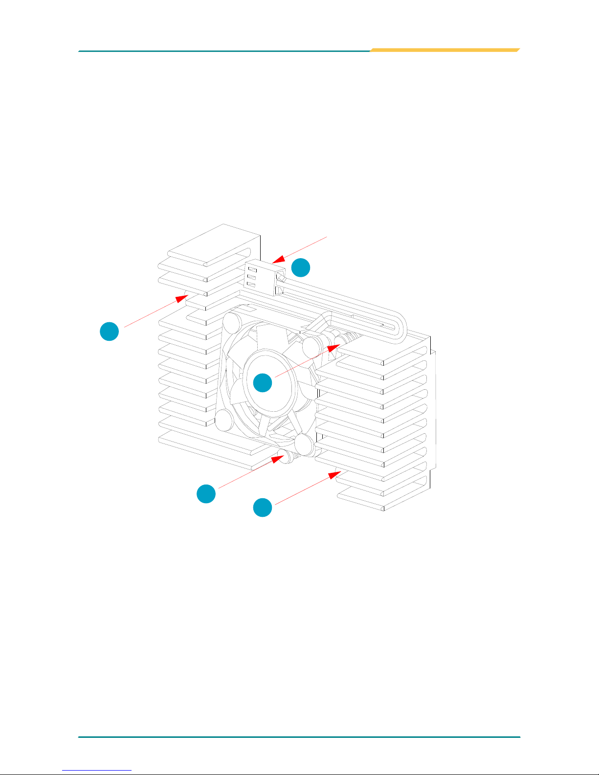
Introduction
Put the heatsink on EmCORE-i9457, and screw it on in the direction of
the board. Insert four screws (No. 1) downward into the holes and turn
them tightly.
Verify the direction is correct (No. 2) and plug the FAN connector into
CPUF1 connector.
1.
2.
1.13 Heatsink Installation
FAN Connector
1
1
1
1
2
- 12 -
Introduction
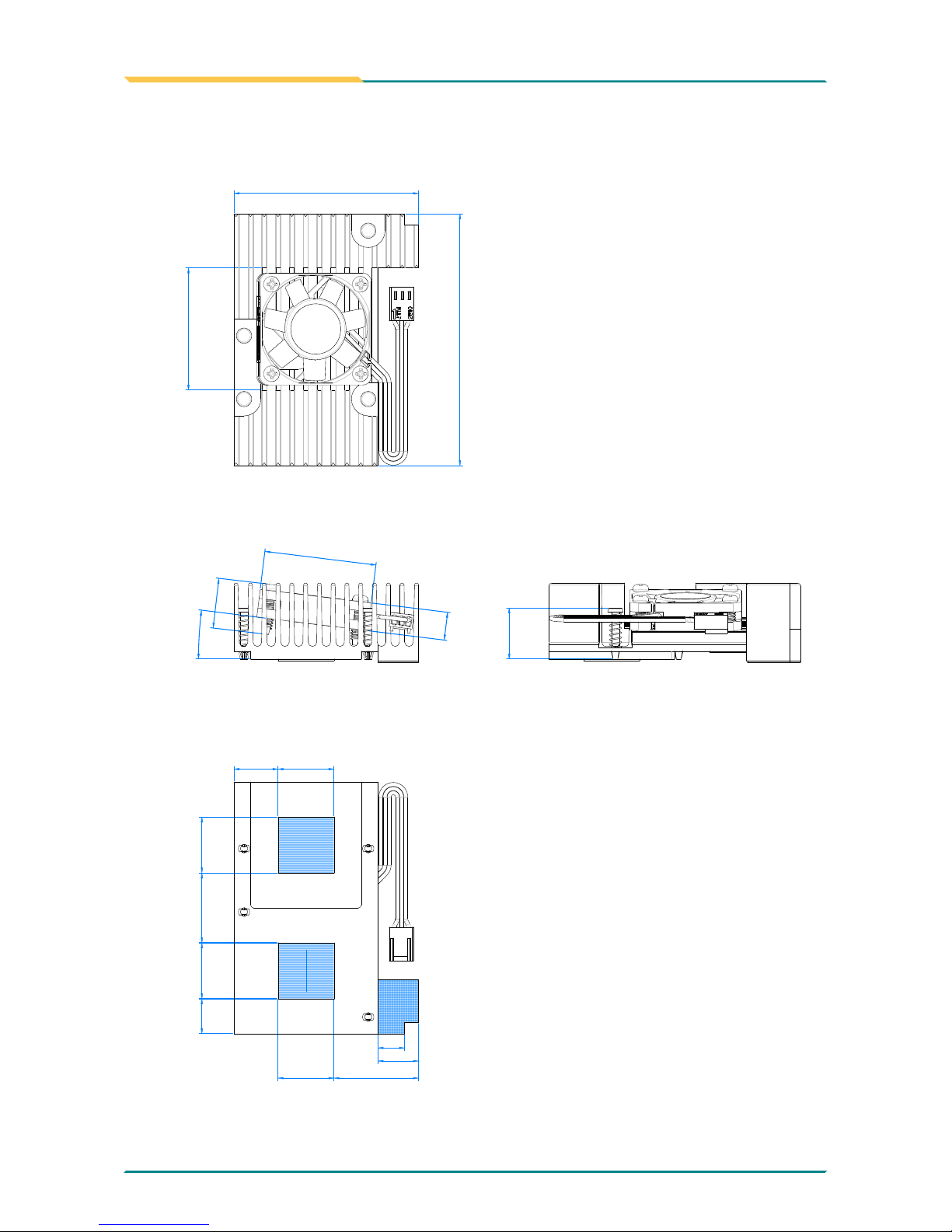
1.14 Heatsink Dimensions
90
66
20
20
20
20
40
14.5
43.7
10
15.75
12.5
7°
17.9
18.3
25
30.25
9.5

- 13 -
Installation
2Chapter 2
Installation
Chapter 2- Installation
- 14 -
Installation
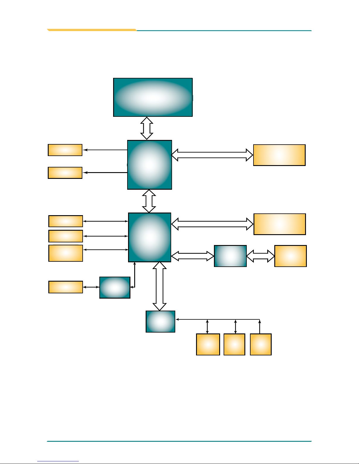
2.1 Block Diagrams
Analog
R.G.B.
VGA
Intel®
945GME
mPGA 478 socket
for Intel® CPU
PCIe LAN
Controller
FSB
667/533MHz
DMI I/F
USB I/F
Serial ATA I/F
IDE ATA I/F
Intel®
ICH7M
1 x IDE
1 x CF
6 x USB
1 x SATA
Audio
Memory Bus
Super IO
COM1
COM2
LPT1
FDD
KB
MS
Codec
AC’97
LPC I/F
1 x LAN
RJ-45
1 x 200-pin DDRII
SO-DIMM socket
PCIe Bus
LVDS
LVDS
PCI Bus
1 x MiniPCI Socket
- 15 -
Installation
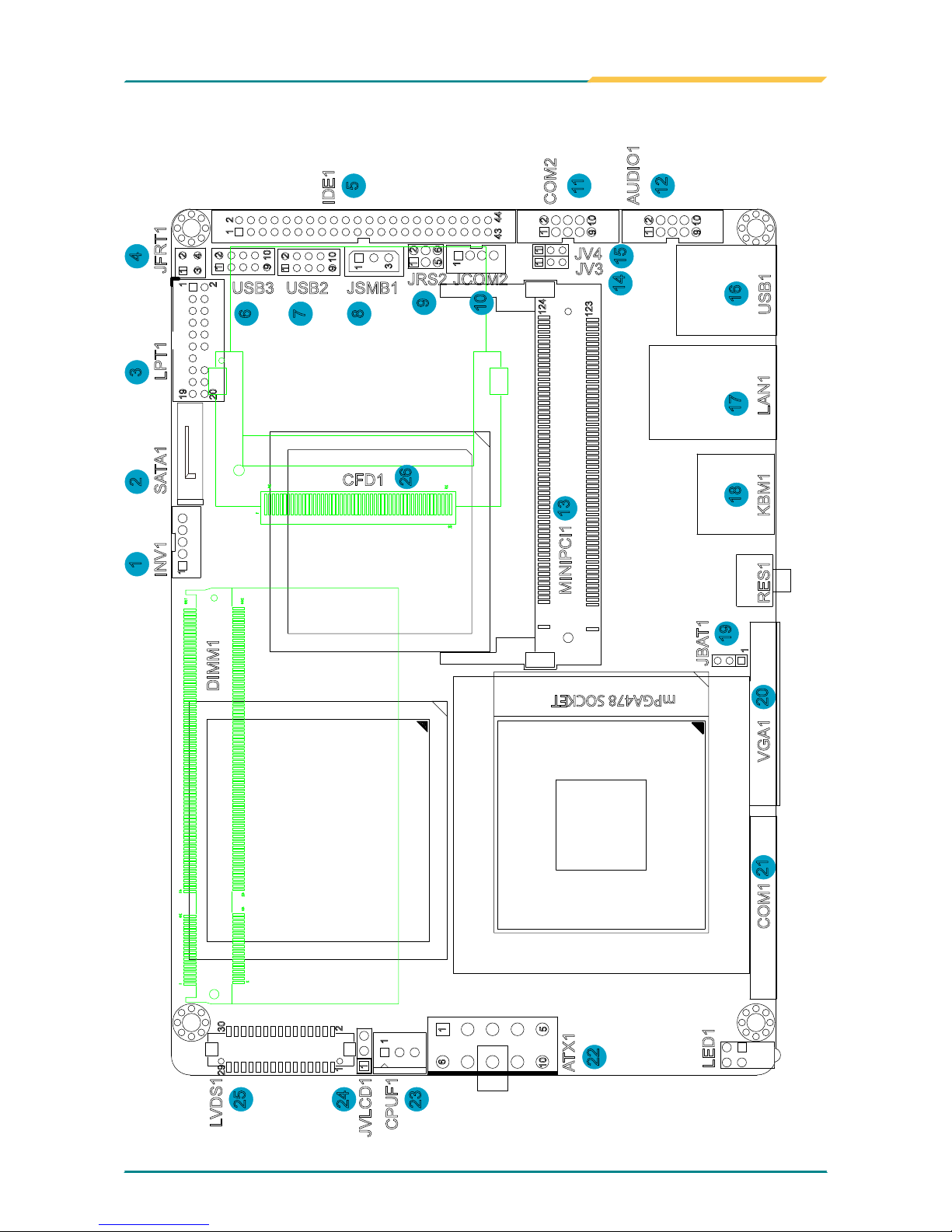
2.2 Jumpers and Connectors
123
124
1
3
4443
21
1
1 1
1 2
9 10
1
1
65
21
5
10
1
6
mPGA478 SOCKET
4
3
2
1
19
20
2
1
1
29 30
2
9
10
10
1 2
9
1
2
1
1
1 2
9 10
25
50
26
1
200
199
2
1
4042
3941
JVLCD1
CPUF1
ATX1
LVDS1
LED1
COM1 VGA1
JBAT1
RES1
KBM1
MINIPCI1
LAN1
USB1
AUDIO1
COM2
IDE1
JFRT1LPT1SATA1INV1
DIMM1
JV3
JV4
JCOM2JRS2
JSMB1
CFD1
USB2USB3
1 2 3 4
6
7
8
5
9
10
14
13
26
15
11
12
1718
19
2021
22
23
24
25
16
1
- 16 -
Installation
Jumpers
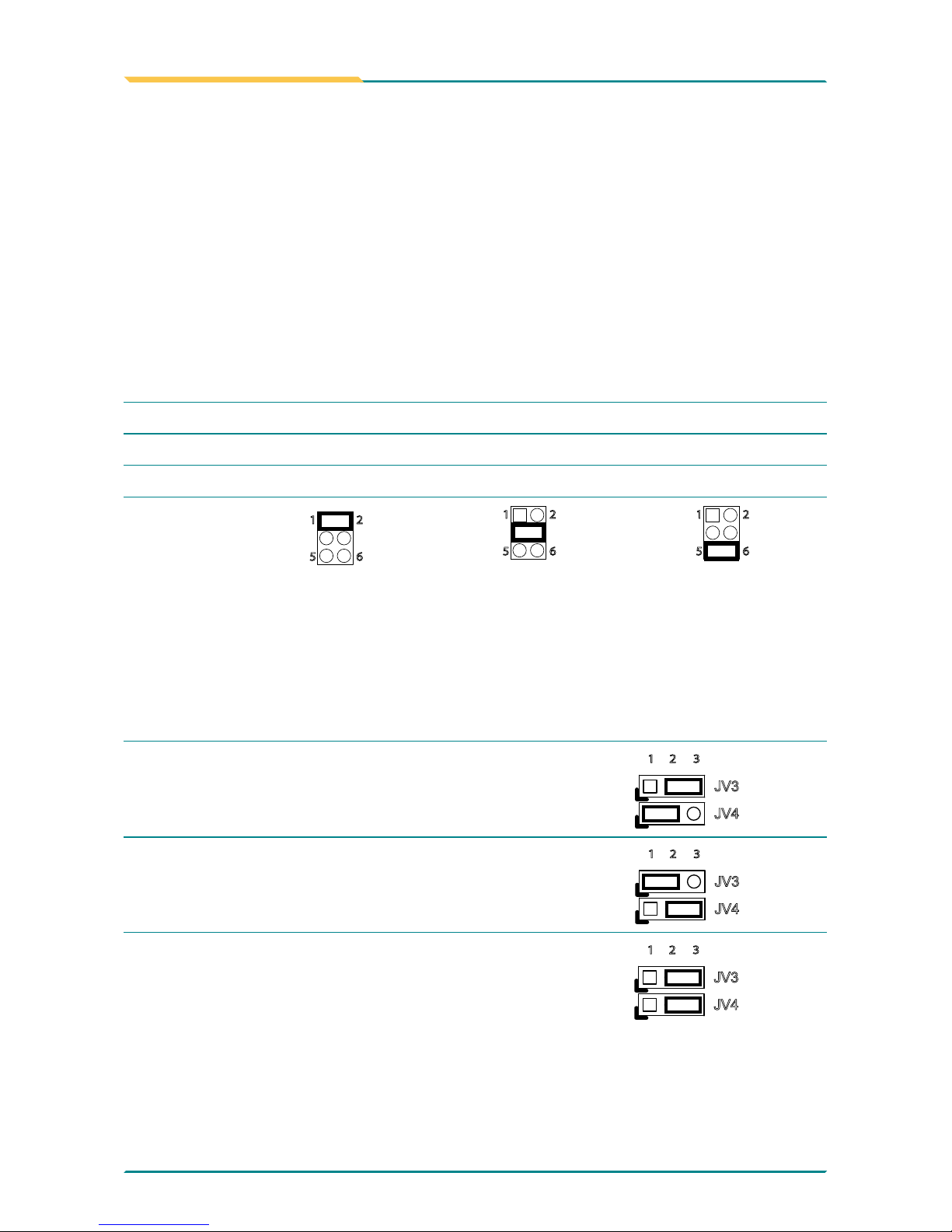
JRS2: COM2 RS-232/422/485 Mode Select (9)
The onboard COM2 port can be congured to operate in RS-422 or RS-485
modes. RS-422 modes differ in the way RX/TX is being handled. Jumper
JRS1 switches between RS-232 or RS-422/485 mode. When JRS1 is set
to RS-422 or RS-485 mode, there will be only +12V output let while JRS1 is
set. All RS-232/422/482 modes are available on COM2.
It can be congured COM2 to operate in RS-232, RS-422 or RS-485 mode
Connector type: 2.00mm pitch 2x3 pin header.
Mode RS-232 (Default) RS-422 RS-485
1-2
ON OFF OFF
3-4
OFF ON OFF
5-6
OFF OFF ON
65
2
1
65
2
1
65
2
1
LV3, LV4: COM2 Power source Special Support (14), (15)
The voltage of COM2 could be selected by LV3 and LV4 to +5V or +12V.
Connector type: 2.54mm pitch 1x3 pin header.
Setup JV3/JV4
POS: +5V on pin 1
JV3
JV4
2 31
POS: +12V on pin 9
JV3
JV4
2 31
POS: +5V on pin 1 and +12V on pin 9
JV3
JV4
2 31
- 17 -
Installation
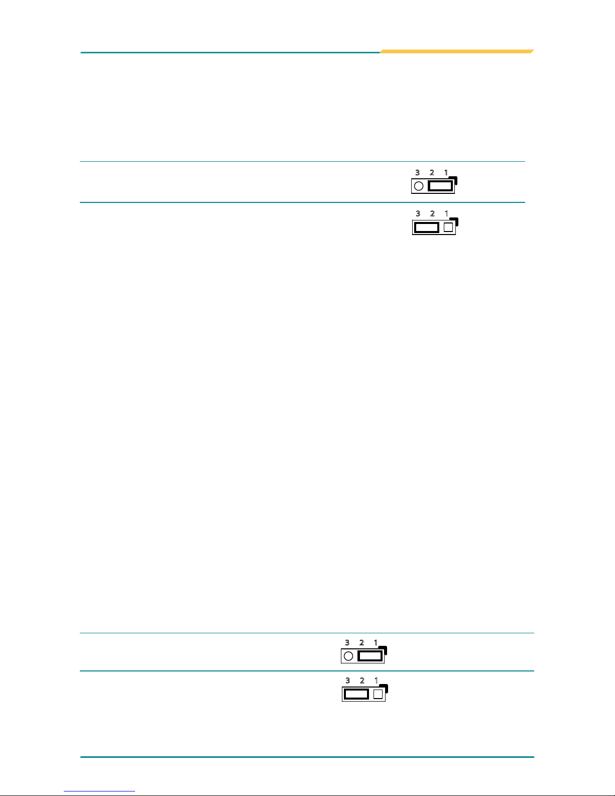
JBAT1: Clear CMOS Setup (19)
If the board refuses to boot due to inappropriate CMOS settings here is how
to proceed to clear (reset) the CMOS to its default values.
Connector type: 2.00 mm pitch 1x3 pin header
Pin Mode
1-2
Keep CMOS (Default)
23 1
2-3 Clear CMOS
23 1
You may need to clear the CMOS if your system cannot boot up because
you forgot your password, the CPU clock setup is incorrect, or the CMOS
settings need to be reset to default values after the system BIOS has been
updated.
Refer to the following solutions to reset your CMOS setting:
Solution A:
1. Power off the system and disconnect the power cable.
2. Place a shunt to short pin 1 and pin 2 of JBAT1 for ve seconds.
3. Place the shunt back to pin 2 and pin 3 of JBAT1.
4. Power on the system.
Solution B:
If the CPU Clock setup is incorrect, you may not be able to boot up. In this
case, follow these instructions:
1. Turn the system off, then on again. The CPU will automatically boot up
using standard parameters.
2. As the system boots, enter BIOS and set up the CPU clock.
Note:
If you are unable to enter BIOS setup, turn the system on and off a few
times.
JVLCD1: LCD Panel Voltage Select (25)
The voltage of LCD panel could be selected by JVLCD1 in +5V or +3.3V.
Connector type: 2.54 mm pitch 1x3 pin header
Pin Voltage
1-2 +5V
23 1
2-3 +3.3V (Default)
23 1
 Loading...