

Mouser ASA-6000, ASA-6800, ASA-6800PS, ASA-6000PS, ASA-6500 User Manual
...
□ After use
Storage and maintenance: when the unit is to be stored for a long period, remove the power supply and bit, open the carbon
brush cover and blow out any accumulated carbon brush dust with compressed air, and wipe the exterior clean. Then store the
screwdriver carefully in a dry, dust-free place away f rom direct sunlight. Store the bit in grease. To ensure continued
serviceability, periodically check and maintain the screwdriver.
Serial No.: ﹍﹍﹍﹍﹍
ASA Industrial Electric Screwdriver User’s Manual
□ Troubleshooting
If the screwdriver does not work properly, check the list below. If you cannot solve the problem do not open the unit. Contact
one of our authorized agents as soon as possible.
(for full-automatic models-low volt. DC motor with soft start controller)
□ If the screwdriver does not run
․Check that the power supply is outputting power.
。Check that the power supply plug is inserted properly and that output plug terminals No.1 (-) and NO.4 (+)
show 30VDC (approximate) between them. If no output is shown, change the power supply.
。Check for a open or short circuit in the 6p-6p cord connec ting the screwdriver to the power supply. If an open
or short circuit is found change the cord or plug. (use plug type 2G2022(6p) or purchase equivalent type)
。Check that the fuse is intact. Caution: when changing the fuse, unplug the power supply.
․Check that the carbon brush is undamaged, that the carbon brush guide cord with the rotor to become too small.
Anyone of these factors could cause the screwdriver to stop rotating or rotate abnormally.
Inspection method: open the carbon brush cover and use a non-conductive insulated rod to gently press the brush. If the
screwdriver resumes rotating, the carbon brush has reached the end of its useful life and must be replaced immediately.
․Check that the rotation direction switch are working pr operly. If no ‘click’ is heard when a trigger is depressed,
it is not working and must be replaced. (make sure to perform this check in a quiet place)
□ If the screwdriver is not rotating normally
․There is a protective circuit within the power supply. Power is only supplied normally from 3 to 5 seconds after
current flow begins.
․If the motor only runs intermittently during ‘Forward’ operation, try ‘Reverse’ operation, or rotate the anvil
90 degrees until a ‘click’ is heard, then re-attempt ‘Forward’ operation.
․Long-term use causes the motor’s commutator to wear down. In this case, it must be replaced.
(this repair must be performed by one of our authorize d agents)
□ If the bit falls out easily or wobbles
․check that the bit matches our specifications. If not, change the bit to one that does.
․If the bit tends to wobble, remove the bit, rotate it 60 or 180 degrees and re-insert it.
□ If the screwdriver does not stop when the selected torque is reached
․An excessive torque setting can cause the screw to strip the threads, with the result that the clutch does not
activate. Lower the torque to a level that does not cause stripping.
․Differences in size between the bit tip and screw slot lengths can cause slopping. Change to a suitable bit tip.
․The brake circuit may be damaged or the sensor switch may have shifted.
(this repair must be performed by one of our authorize d agents)
□ Warranty
We provide a one-year free repair service warranty with this product. The warranty is good for one year from the date of
purchase entered on the Product Information Form. The retailer’s stamp must appear on the form to confirm the date. However,
the following circumstances we will charge the user for any parts and labor cost associated with repairs.
□ For repairs involving normal wear to parts including carbon brushes, bits and power cord, and also to the exterior surface.
□ If the screwdriver was connected to a power source of the incorrect voltage.
□ If there was inappropriate use or an attempt to repair the unit by the user.
□ After the period of the guarantee, or if the user cannot present the manual with stamped Product Information Form.
Retailer’s
Stamp
◎ Specifications and design may be changed without notice for improvement(A-4)
□ A
Word of Thanks to Our Customers
Thank you for choosing lightweight and powerful electric screwdrivers. In order to insure maximum performance and product
life, please read through this manual before using your screwdriver.
□ Feature
□ Our screwdrivers are designed for use with precision torque locking screws. It can be used for assembly of middle and
large range items such as home appliances, computers furniture and car industry etc.
□ Low vibration, low noise, meets environmental protection demands.
□ Low-voltage electronic braking circuit for precision torque control, low brea kdown rate and long product life.
□ Low-voltage DC motor for safety and prevention of electric shocks.
□ Design features separation of screwdriver and control for low repair costs and higher serviceability rate.
□ Switching power supply plugs directly into screwdriver and builds a soft start circuit, provide more accurate torque,
longer motor life and safe operation.
□ Right-angel (90°) head adapter attaches easily to screwdriver for use in small spaces (>60mm), operates smoothly.
(Optional for 1/4" hex shank only)
□ Ergonomically designed exterior reduces work fatigue and increases productivity.
□ Specifications
Model
ASA-6000 ASA-6000PS ASA-6500 ASA-6500PS ASA-6800 ASA-6800PS
Power source 30VDC
Torque range
Kgf-cm/lbf-in
2.0-12.0 / 1.7-10.4 4.0-20.0 / 3.5-17.4 5.0-25.0 / 4.3-21.7
Accuracy ±3%
No load speed / rpm 1150 1000 1000 700
Torque setting Stepless
Machine screw
mm / in
2.0-3.0 / 0.08-0.12 2.6-4.0 / 0.10-0.16 3.0-5.0 / 0.12-0.20
Available
Machine screw
mm / in
2.0-2.6 / 0.08-0.10 2.3-3.5 / 0.09-0.14 2.6-4.0 / 0.10-0.16
Weight g/lb 490 / 1.1
Length mm/in 228 / 9.0 237 / 9.3 228 / 9.0 237 / 9.3 228 / 9.0 237 / 9.3
Available bit shank
5ψ/5mm Hex shank、1/4’’ Hex shank
Power consumption 30 40 40
Available power supply
APS-30UA、APS-30UE,APT-65
Clutch impact Just one time when torque up
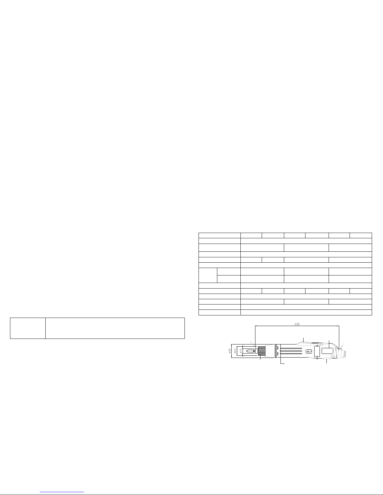
□ Outline (this drawing applies only to 1/4” hex. bit shank screwdrivers)
ASA-6500 1000RPM
INPUT :30VDC 1.0A
Torque:4.0-18.0 Kgf-cm
ψ34
(Egg-shaed)
BONNET
FWD-OFF-REV SW
HANGER
RING
TRIGGER
(POWER SWITCH)
LABEL
TORQUE REGULATING HANDLE
BIT SLIDE SLEEVE
Lever
start
type
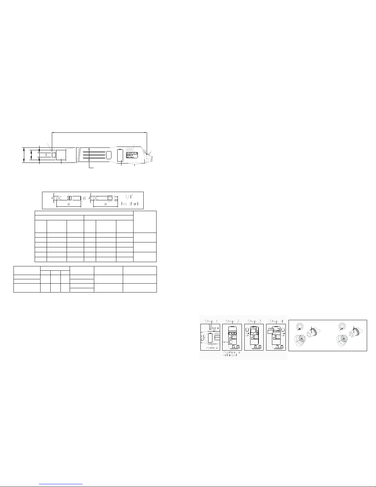
237
ASA
ψ38.5
ψ25
ψ15.7
BONNET
FWD-OFF
TORQUE REGULATING HANDLE
ψ33/ψ35.5
(Egg-shaped)
-REV SW
HANGER
RING
LABEL
BIT SLIDE SLEEVE
Push
start
type
□
Accessories
This product comes supplied with a pair of carbon brush and two bits.
□ Bits(one set per screwdriver)
Start and stop: For lever start type. The motor begins running when the lever is depressed and stops when it is released.
For push to start type. When the screwdriver is pressed onto a screw perpendicularly, inwards pressure from the
screwdriver bit engages the power switch, and the motor begins running. When the pressure on the screwdriver is released,
the bit and power switch revert to their original positions and the motor stops running.
Driving and removing screw: Before operation, set forward/reverse switch properly. To drive a screw, set the switch to the
forward(FWD) position. To remove a screw, set it to the reverse(REV) position. Press the screwdriver onto the screw
perpendicularly to being operation. Note: Don’t operate the FWD/REV switch when the motor is running.
When removing screws: when a previously driven screw cannot be removed using the same torque that it was driven with,
raise the torque setting. After the screw is removed, return the regulating handle to its original setting. To simplify this
operation, note the number ‘click’ sounds generated as the regulating handle is turned. When removing a screw, if the
required torque is higher than the screwdriver’s output torque, the clutch may not disengage, causing the user’s hand and
arm to be twisted. In this case immediately set the forward/reverse switch to “OFF” to cut the motor power and prevent
injury.
Secure screwdriver during operation: During operation, hang the screwdriver up securely (as from balancer) in order to
prevent it from being knocked down and suffering external cracking, internal damage, or a snapped power cord.
Changing the carbon brush: Insert a slotted hand screwdriver with a 2mm to 4mm head edge into the slot and lever up the
carbon maintenance bonnet. Remove the used carbon brush and insert a new carbon brush of the same specifications in
the empty space. To complete the operation, close the carbon brush cove r tightly by pressure.
(as shown below step 1 to step 4)
Note:
․When changing the carbon brush first unplug the screwdriver. Use a factory specification carbon brush.
․The notch on the carbon brush surface must face into the direction of the rotor rotation.
When the selected torque is reached: This product features an internal clutch assembly. When a screw is driven and the
selected torque is reached, the clutch assembly will automatically disengage and a ‘click’ will be heard. At this point, even
if the ‘trigger’lever or depress force is not released, the power to the motor will be automatica lly cut off.
Note: When driving screw, grasp the screwdriver firmly in order to prevent upwards recoil generated by the clutch
release from forcing the screwdriver bit edge form the screw slot and damaging slot.
Torque settings: Use the regulating handle to set the torque. Turning it in a clockwise direction into the screwdriver will
increase the torque. Turning it counterc lockwise out of the screwdriver will decrease the torque.
Note: The engraved markings on the engraving ring are for reference only and do not indicate torque output.
Torque output can only be determined by repeated testing with a torque meter or hand-held spanner torque
meter. To prevent your torque setting from being changed we can provide a torque cover (optional) which
covers and secures the regulating handle.
Bit insertion: Use your finger to depress the slide sleeve into the screwdriver and insert an appropriate bit. When the slide
sleeve is released, the bit will be automatically engaged.
Note: Do not hammer the bit in or pull it out forcibly.
Bit specifications
ψ5.0
1/4"Hex
Tip
NO.
Tip
DiameterD P#
Tip
NO.
Tip
DiameterD P#
Available
Screwdriver
Model
#1
ψ3.0
7W3644 #1
ψ3.0
7W6644
#2
ψ5.0
7W3864 #2
ψ4.5
7W6764
ASA6000
ASA6000PS
#1
ψ3.0
7W3644 #1
ψ3.0
7W6644
#2
ψ5.0
7W3864 #2
ψ6.0
7W6964
ASA6500
ASA6500PS
#1
ψ5.0
7W3844 #1
ψ4.5
7W6744
#2
ψ5.0
7W3864 #2
ψ6.0
7W6964
ASA6800
ASA6800PS
□ Power supply(optional)
Dimension mm
Model
L W H
Operation volt
(AC)
Output volt
(DC)
Weight
(g/lb)
APS-30UA 100-120V
APS-30UE
154 84 52
220-240V
30V(constant) 620/1.36
115V
APT-65 220 118 96
230V
30V/20V 3400/7.5
․APS-30UA/APS-30UE are switching circuit power supplies with 0.8"max time settable soft start circuit.
They are light and small, consume little electricity and supply stabile voltage.
․Stabilizer accessories:2 locking ties, 2 pieces of
double-sides tape(only for APS-30UA/APS-30UE)
□ Before use, read the following
Use the correct voltage: Carefully check the voltage shown on the power supply and this manual and determine
the correct voltage. Only plug the unit into a power source of the correct voltage.
Determine the appropriate torque range: choose the correct screwdriver for the torque you will require. To
lengthen product life, avoid long-term high torque use.
Make sure the screwdriver is undamaged: If the power code is scraped or damaged, it should be immediately
unplugged and replaced to avoid electric shocks or a short circuit that could result in fire.
Use in an appropriate work environment: To ensure safety, do not use in high temperature, high humidity
environments or near flammable materials. Keep the power cord away from tools or equipment that might scrape
or melt it.
When plugging in or unplugging the power cord, hold the plug firmly. Never pull on the cord.
□ Method of operation and important points
Brace fastened objects securely-Before operation, refer to “torque settings” item to determine the appropriate
torque , and adjust the screwdriver to the appropriate torque. Make sure that the fastend objects are securely braced,
and then begin operation. This procedure will avoid hazardous rapid rotation of the fastened objects due to
excessive torque or insufficient bracing.
CONVEX POINT
CONVEX POINT
GUIDE NOTCH
GUIDE NOTCH
RECEPTACLE
(SCREWDRIVER SIDE) (SCREWDRIVER SIDE)
RECEPTACLE
6P PLUG5P P
LUG
 Loading...