

Page 1
&
PULSETOOLS
INSTRUCTIONMANUAL
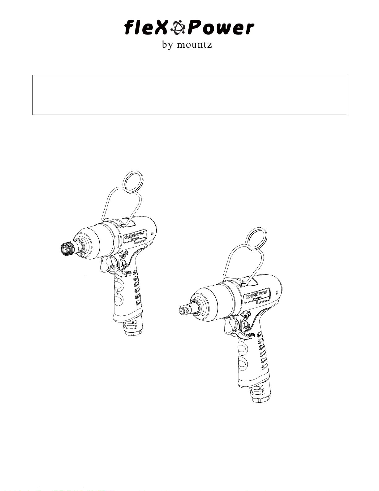
PISTOL TYPE
MAINTENANCE
Rev 3.0 (7/12/2011)
READ ALL THE INSTRUCTIONS COMPLETELY BEFORE OPERATION.
COMPLY WITH ALL THE INSTRUCTIONS AND RULES IN THIS MANUAL AND SAVE THIS MANUAL
FOR FUTURE REFERENCE.
1
Page 2

CHART OF CONTENTS
General Safety Rules and Replacement and Maintenance ………………………………………………….. Page 2
Steps for Torque Adjustment – Pistol Type ...………………………………………………………………….. Page 3
Recommendations for service…………………………………………………………………………………… Page 4, 5
Disassembly / Assembly for Pulse Wrenches and Drivers – Pistol Type, Non-Shut off …………….……. Page 6
Pulse Mechanism Disassembly ……………………………………………………………………….. Page 6
Pulse Unit Assembly ……………………………………………………………………………………. Page 9
Housing and Motor Set Disassembly …………………………………………………………………. Page 20
Housing and Motor Set Assembly …………………………………………………………………….. Page 22
Disassembly/ Assembly for Pulse Wrenches and Drivers – Pistol Type, Shut off …………………………. Page 26
Pulse Mechanism Disassembly ……………………………………………………………………….. Page 26
Pulse Unit Assembly ……………………………………………………………………………………. Page 29
Housing and Motor Set Disassembly …………………………………………………………………. Page 40
Housing and Motor Set Assembly …………………………………………………………………….. Page 44
Trouble Shotting………………………………………………………………………..…………………………. Page 46
Mountz Inc. 1080N 11th Street, San Jose CA 95112 Ph (408) 292-2214 Fax (408) 292-2733 www.mountztorque.com
2
Page 3

General Safety Rules
ALWAYS OBSERVE THE FOLLOWING RULES TO ASSURE SAFE USE OF THE TOOLS!!
Do not operate the pulse tools unless you fully understand the instructions contained in
this manual. If any unclear, please contact the agents.
Never expose to rain or use in damp locations.
Always use the proper pressure at air inlet. Apply either less or exceed air inlet pre ssure
will affect the performance of the tools, including quality, torque, function, and life, then
lead to damage.
Air inlet pressure standard
70PSI – 85PSI (5.2kg/cm
2
~6.2kg/cm2)
Always add oil about 0.5~1cc at air inlets at least every week to maintain the
performance and the life of the pulse tools.
Keep children away. Tools must need to be kept in a safe and clean position where
children cannot reach.
DO NOT force tools. The tool will be damaged easily and quickly if over-load over 15
seconds.
Always use the proper length of air hose. The length of air hose shall not exceed
5 meters
, or the pressure reduces. Do be sure the air inlet pressure is in between the
standard number(70PSI – 85PSI) before operating tools.
Always use safety glasses and earphone.
Always operate the tools by two hands. One hand operation may cause risk of injury to
persons.
Disconnect the air hose and the quick nipple after operating tools. Be sure to return
tools to safety position. Tools drop or unintentionally contact can cause risk of injury.
Install the safety buckle to avoid tools drop while operating in high position.
Never contact with any electricity conducted objects to avoid electricity shock hazard.
Replacement and Maintenance
(1) Never try to repair or replace the defective tools by others under the warranty period. The
authorized service centers have the right to refuse or cert ain fee may incur for extra rep air
work.
(2) Keep all related servicing records for future repairs, maintenance, and adjustment.
(3) The warranty does not apply to accessories or damage caused where repairs have been
made or attempted by others
(4) Mountz will repair, without charge, any defects due to faulty material under the warranty
period
(5) The warranty do es not cover part fai lures due to normal wear and tool abuse, and damage
caused due to any appropriate appliances, i.e. tool over loaded, improper air inlet
pressure and air hose size, unauthorized replacement parts.
Mountz Inc. 1080N 11th Street, San Jose CA 95112 Ph (408) 292-2214 Fax (408) 292-2733 www.mountztorque.com
3
Page 4
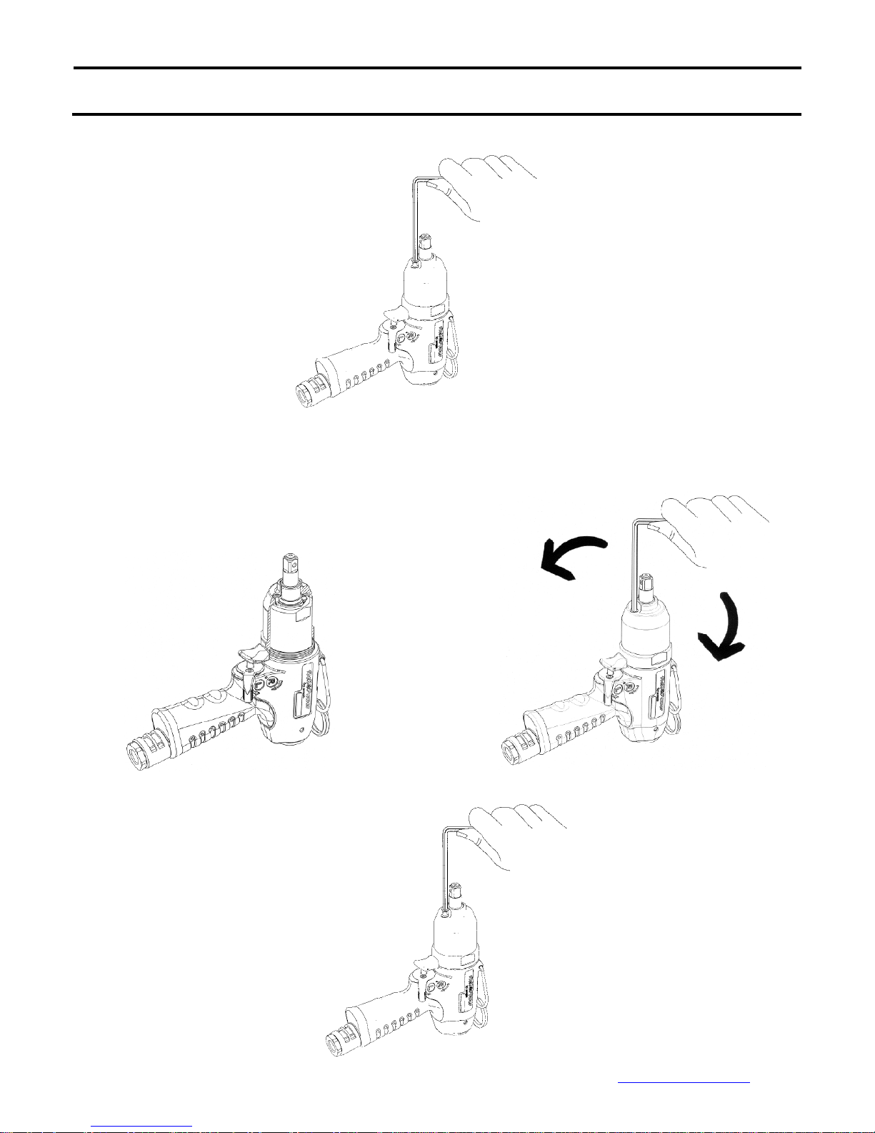
Steps for Torque Adjustment – Pistol Type
1. Loosen the screw on the pulse unit housing.
Fig.1
2. Rotate the anvil manually; make the valve screw inside the pulse unit aim at the hole (where the screw taken
off). Then, use the attached tool to adjust the torque. Torque increased by turning clockwise and vise versa。
Reduce torque
3. Tighten the screw back to the pulse unit housing.
Fig.2
Increase torque
Fig.3
Mountz Inc. 1080N 11th Street, San Jose CA 95112 Ph (408) 292-2214 Fax (408) 292-2733 www.mountztorque.com
Fig.4
4
Page 5

RECOMMENDATIONS FOR SERVICE
The pulse tool requires regular maintenance to ensure the tool operates at optimal performance. The type of routine
maintenance and the frequency is dependent on the application and how the tool is used. The pulse tool requires preventive
maintenance like oil changes and have the parts inspected periodically. Regular oil changes will increase the life cy cle of the
tool, reduce maintenance costs and allow the tool operate properly.
When is first service required? There are several factors that influence the maintenance schedu le: 1: Type of a pplication, 2)
The torque setting within the torque range of the pulse tool, and 3) The number of cycles the tool is used daily, weekly and
monthly.
1) The first service is recommended at 250,000 pulse-seconds. The oil needs to be changed. Inspect all the soft parts of the
pulse unit (the soft parts are referenced as the "Repair Kit" - see parts list documen t for that model). The Repair Kit includes
all the necessary parts and it is recommend to be performed every six months at minimum, based upon use of the tool.
2) The second service is recommended at 500,000 pulse-seconds. The oil needs to be changed. All soft parts of the pulse
unit need to be replaced (the soft parts are referenced as the "Repair Kit" - see parts list document for that model). Inspect
the hard parts of the pulse tool (the hard parts are referenced as the "Service Kit" - see parts list document for that model).
This maintenance service may occur once or twice a year at minimum, based upon use of the tool.
It is recommended that after 250,000 pulse-seconds the pulse tool should be evaluated for general performance and oil
condition as part of its standard preventive maintenance. If the tool fails before the 250,000 pulses-seconds then the pulse
unit needs to be rebuilt, with the "Repair Kit" and "Service Kit" (see parts list document for that model). Note! Always it is
important to make sure the tool has clean, dry and lubricated air at the recommended pressure supplied to it.
A pulse-second is not every second the tool is running, only when it’s "pulsing" and applying torque. Typically, the tool does
not start pulsing until after the fastener is snug, unless there’s considerable prevailing torque. When operating the tool on
the fastener, start counting once the tool begins pulsing. You can use a watch with a second hand and time it until the tool
automatically shuts-off. Use the information to calculate how many pulse-seconds the tool performs per application each
day. Then perform some basic math to calculate the tool’s maintenance schedule. Use this formula.
# Pulsing Seconds ÷ Total of Pulsing Time = No Cycles
Note! Please include the rework, reverse, or retightening time involved on the operation to calculate the accurate
pulsing time. Here is an example:
Pulsing Time = 2 seconds
Pulses- seconds recommended = 250,000
250,000 pulses-sec ÷ 2 sec = 125,000 cycles
Taking the example above, to estimate the maintenance period can be follow by the following
No of Fasteners Pulsing Time per
Fastener
7 2 seconds 300 125,000 /(300*7) = 59 59 days
Mountz Inc. 1080N 11th Street, San Jose CA 95112 Ph (408) 292-2214 Fax (408) 292-2733 www.mountztorque.com
No of parts
assembled per day
Calculation No of days to inspect the
tool
5
Page 6

Regularly the hard joint pulse in average 0.5 sec, and the soft join t is average is 2 se conds, base d on the a bove exa mple, if
the tool has not drop-off the performance, the service to change the oil fluid is after approximately 59 work days. However
the application can be expose of extreme conditions (poor air supply, extended pulsing times, torque setting at the high end
of tool range, high number of cycles), the maintenances intervals may need to be reduced.
TOOL MODEL Repair Kit Item No Service Kit Item No
AUTO SHUT-OFF MODELS
FLEXS-40P 63- IS40RK -E05A 63- IS40SK -E05A
FLEXS-50P 63- IS50RK -E05A 63- IS50SK -E05A
FLEXS-60P 63- IS60RK -E05A 63- IS60SK -E05A
FLEXS-70P 63- IS70RK -E05A 63- IS70SK -E05A
FLEXS-90P 63- IS90RK -E05A 63- IS90SK -E05A
FLEXS-100P 63- IS100RK -E05A 63- IS100SK -E05A
FLEXS-130P 63- IS130RK -E05A 63- IS130SK -E05A
FLEXS-150P 63- IS150RK -E05A 63- IS150SK -E05A
FLEXS-30PX 63- IS30DRK -E05A 63- IS30DSK -E05A
FLEXS-40PX 63- IS40DRK -E05A 63- IS40DSK -E05A
FLEXS-50PX 63- IS50DRK -E05A 63- IS50DSK -E05A
FLEXS-60PX 63- IS60DRK -E05A 63- IS60DSK -E05A
NON SHUT-OFF MODELS
FLEX-40P 63- I40RK -E05A 63- I40SK -E05A
FLEX-50P 63-I50RK -E05A 63-I50SK -E05A
FLEX-60P 63-I60RK -E05A 63-I60SK -E05A
FLEX-70P 63-I70RK -E05A 63-I70SK -E05A
FLEX-90P 63-I90RK -E05A 63-I90SK -E05A
FLEX-100P 63-I100RK -E05A 63-I100SK -E05A
FLEX-130P 63-I130RK -E05A 63-I130SK -E05A
FLEX-150P 63-I150RK -E05A 63-I150SK -E05A
FLEX-30PX 63- I30DRK -E05A 63- I30DSK -E05A
FLEX-40PX 63- I40DRK -E05A 63- I40DSK -E05A
FLEX-50PX 63-I50DRK -E05A 63-I50DSK -E05A
FLEX-60PX 63-I60DRK -E05A 63-I60DSK -E05A
Mountz Inc. 1080N 11th Street, San Jose CA 95112 Ph (408) 292-2214 Fax (408) 292-2733 www.mountztorque.com
6
Page 7
DISASSEMBLY / ASSEMBLY FOR PULSE WRENCHES
FLEX-40P, FLEX-50P, FLEX-60P, FLEX-70P, FLEX-90P, FLEX-100P, FLEX-130P, FLEX-150P FLEX-30PX, FLEX-40PX,
FLEX-50PX, FLEX-60PX
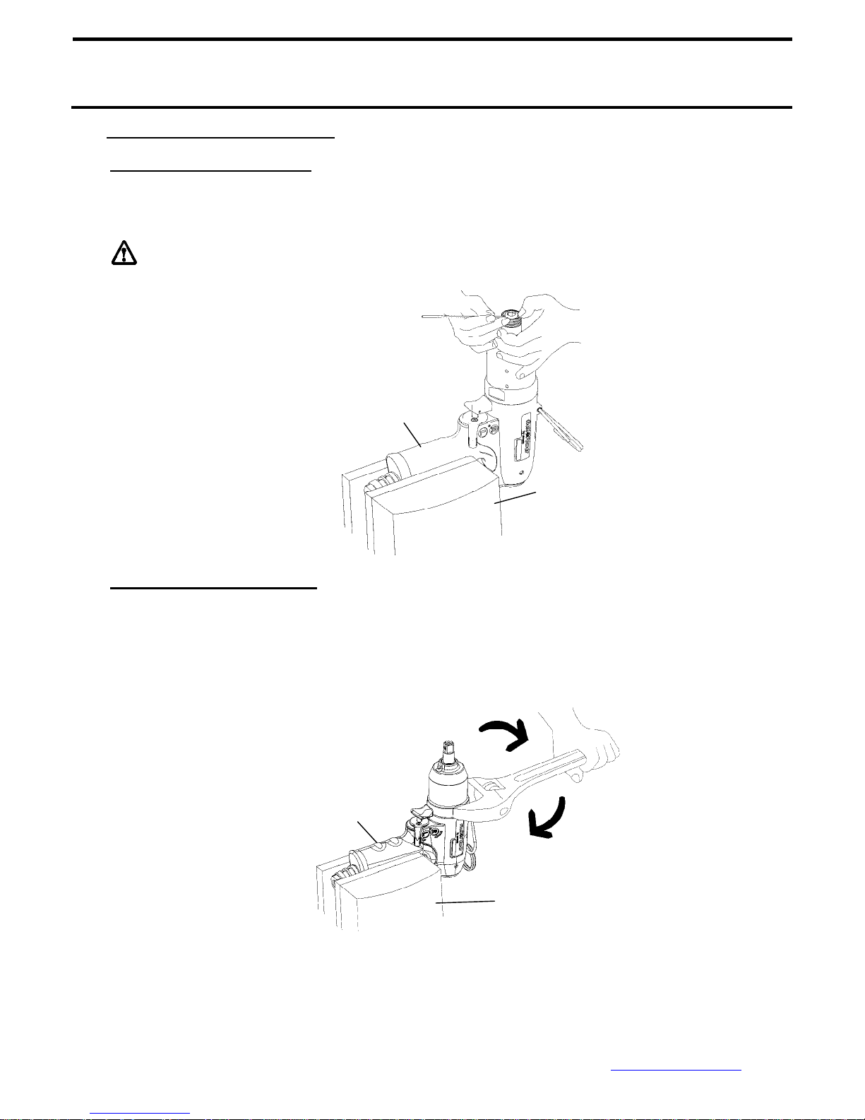
PULSE MECHANISM DISASSEMBLY
1.0 Quick Change Holder Assembly
Press down the hold spacer, and find the anvil collar. Use the a needle like stuff to get the anvil collar out,
then take the quick change holder, the hold spacer, the spring, and the steel ball apart.
The steel ball may drop off when taking out the Quick Change Holder
Note: Handle rubber must be
covered by a piece of cloth to
avoid damage
: (for Model No. FLEX-30PX, FLEX-40PX, FLEX-50PX, FLEX-60PX)
Vise
Fig.5
2.0 Pulse Unit Housing Disassembly
Fix the tool by a vise, use an adjustable Chart wrench clockwise to loosen the pulse unit housing until the
pulse unit housing detach from the motor housing. Then, take the pulse unit out (Fig 6).
Note: Handle rubber must be
covered by a piece of cloth to
avoid damage
:
Vise
Fig.6
Mountz Inc. 1080N 11th Street, San Jose CA 95112 Ph (408) 292-2214 Fax (408) 292-2733 www.mountztorque.com
7
Page 8
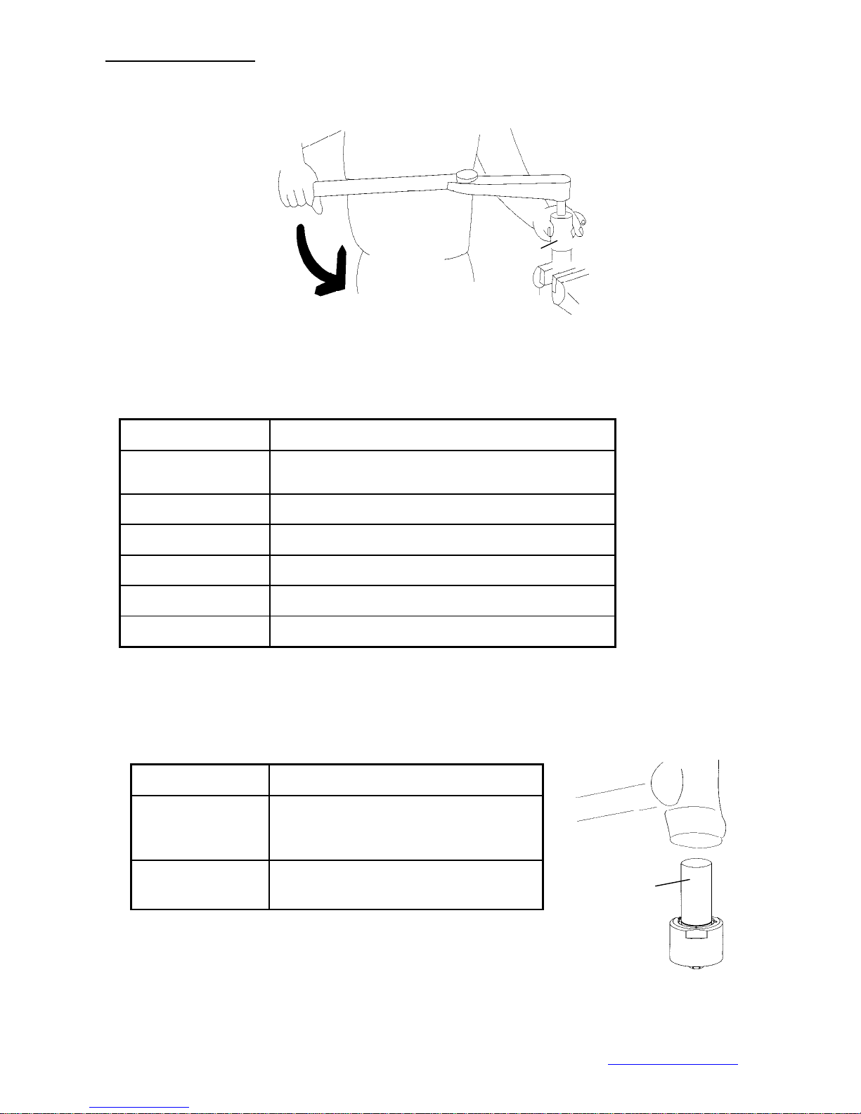
3.0 Pulse Unit Disassembly
App
3.1 Fix the pulse unit by a vise. Use the appliance (see Chart 1) to loosen the lock nut on the pulse unit,
Fig. 7.
Note: LoctIte was applied on the lock nut when tools assembled.
3.2 Put the Appliance, see Chart 2, on the anvil and tap on it slightly to detach the interior parts from
Appliance No. Apply to
63-TDI-40RT001
63-TDI-70RT001 FLEX-70P
63-TDI-90RT001 FLEX-90P
63-TDI-100RT001 FLEX-100P
63-TDI-130RT001 FLEX-130P
63-TDI-150RT001 FLEX-150P
the pulse unit, Fig. 8.
:
Appliance
Fig.7
FLEX-40P, FLEX-50P, FLEX-60P, FLEX-30PX ,
FLEX-40PX , FLEX-50PX , FLEX-60PX
Chart 1
Chart 2
Appliance No. Apply to
FLEX-40P, FLEX-50P, FLEX-60P,
63-TDI-40RT002
63-TDI-90RT002
FLEX-70P,FLEX-30PX ,FLEX-40PX ,
FLEX-50PX , FLEX-60PX
FLEX-90P, FLEX-100P, FLEX-130P,
FLEX-150P
Mountz Inc. 1080N 11th Street, San Jose CA 95112 Ph (408) 292-2214 Fax (408) 292-2733 www.mountztorque.com
liance
Fig. 8
8
Page 9
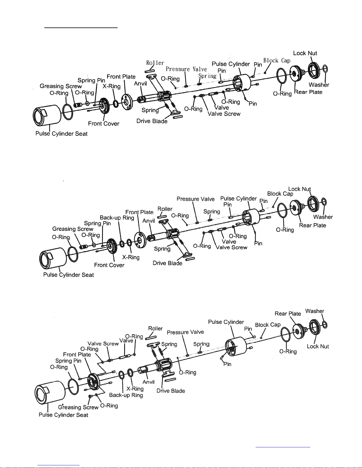
4.0 Parts of Pulse Cylinder Unit:
a) FLEX-40P, FLEX-50P, FLEX-60P
b) FLEX-70P, FLEX-90P
c) FLEX-100P
Mountz Inc. 1080N 11th Street, San Jose CA 95112 Ph (408) 292-2214 Fax (408) 292-2733 www.mountztorque.com
9
Page 10
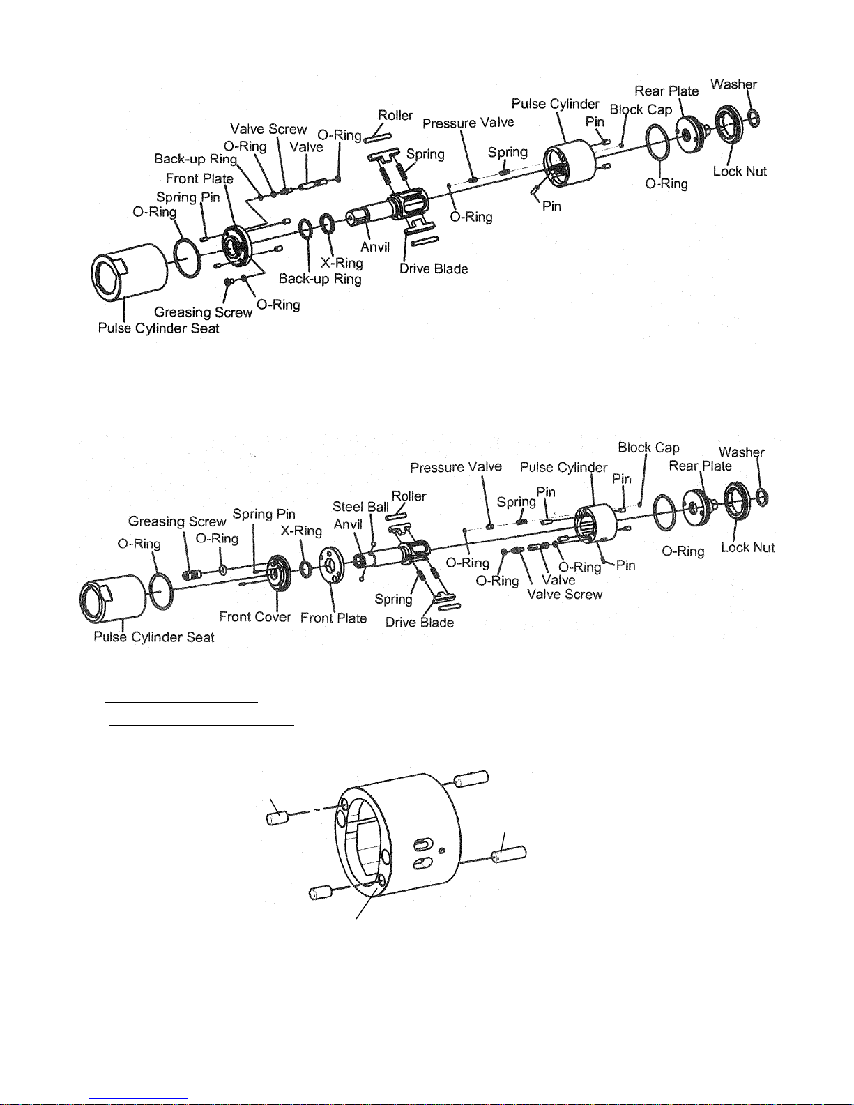
d) FLEX-130P
e) FLEX-30PX ,FLEX-40PX , FLEX-50PX , FLEX-60PX
PULSE UNIT ASSEMBLY
:
1.0 Pulse Cylinder Unit Assembly
1.1 Install the pins on both sides of the pulse cylinder. (Fig. 9)
Pin
Pulse Cylinder
1.2 Sleeve the O-ring to the valve and install the valve into the big hole on the pulse cylinder. (Step 1;
Fig.10)
1.3 Insert the pin into the hole on the side of the pulse cylinder. (Step 2; Fig.11)
1.4 Screw the valve screw to the pressure valve. (Step 3; Fig.11)
Mountz Inc. 1080N 11th Street, San Jose CA 95112 Ph (408) 292-2214 Fax (408) 292-2733 www.mountztorque.com
:
Pin
Fig.9
10
Page 11
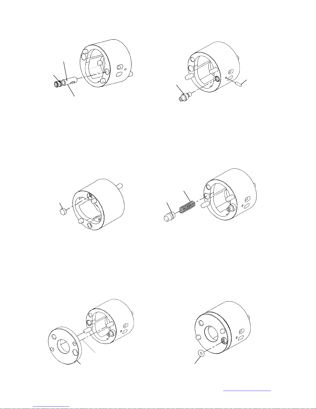
NOTE: the valve screw MUST screw to the most bottom position certainly.
Small hole
O-ring
Valve screw
Pin
Big hole
Step 1; Fig.10
Step 2; Fig.11
1.5 Plug the block cap into the hole and make sure it is parallel to the surface of the pulse cylinder.
(Step 4; Fig. 12)
1.6
Put the spring into the hole then install the pressure valve that with the O-ring sleeved.
(Step 5; Fig. 13)
Spring
Block Cap
Pressure Valve
Step 4; Fig.12
Step 5; Fig.13
1.7 Install the front plate and make sure the corresponding position with the pins. (Step 6; Fig. 14)
1.8 Sleeve the O-ring on the valve screw and press into the hole. Make sure it is parallel to the surface
of the front plate. (Step 7; Fig. 15)
Corresponding position
Front Plate
Step 6; Fig.14
O-ring
Step 7; Fig.15
Mountz Inc. 1080N 11th Street, San Jose CA 95112 Ph (408) 292-2214 Fax (408) 292-2733 www.mountztorque.com
11
Page 12
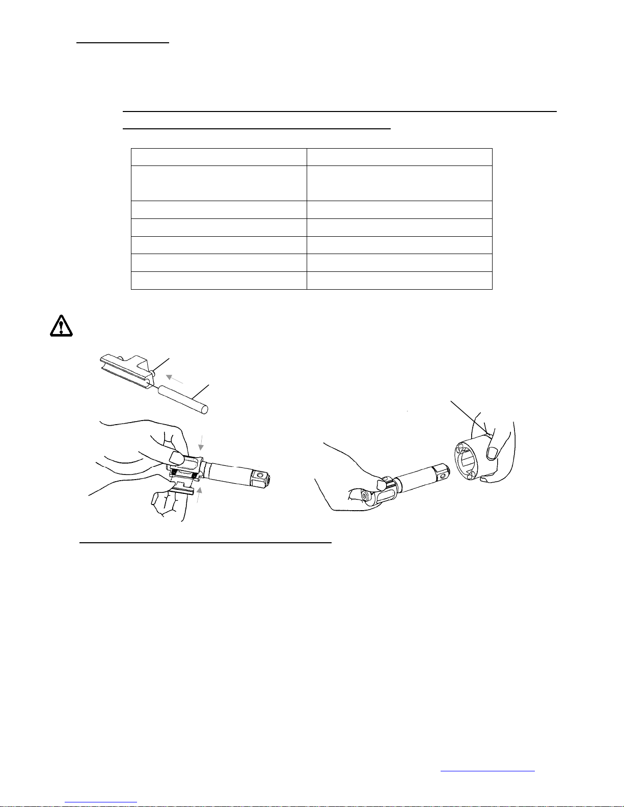
2.0 Anvil Unit Assembly
Install the roller to the drive blade, then insert the springs into the anvil and press the blades from both
sides. Finally put the anvil to the pulse cylinder to complete the anvil unit assembly.
NOTE: RECOMMENDED UTILIZE THE SPECIAL FIXTURE FOR EASIER INSTALLATION FOR THE ANVIL
WITH THE ROLLER AND THE BLADE INTO THE CYLINDER
FIXTURE PART No TOOL MODEL
63-I40AST-001K FLEX-40P, FLEX-50P, FLEX-60P,
FLEX-40PX, FLEX-50PX, FLEX-60PX,
63-I70AST-001K FLEX-70P
63-I90AST-001K FLEX-90P
63-I100AST-001K FLEX-100P
63-I130AST-001K FLEX-130P
63-I150AST-001K FLEX-150P
MUST follow the direction as Fig.18 showed while installing the anvil unit into the pulse cylinder; be sure to
aim at the highest points by two sides of the interior pulse unit and press the two drive blades in slowly.
Drive Blade
Roller
Front Plate
Fig.16
Press
3.0 Front Cover and Rear Plate of Pulse Cylinder Assembly ( For the models FLEX-40P, FLEX-50P, FLEX-60P,
FLEX-30PX ,FLEX-40PX , FLEX-50PX , FLEX-60PX)
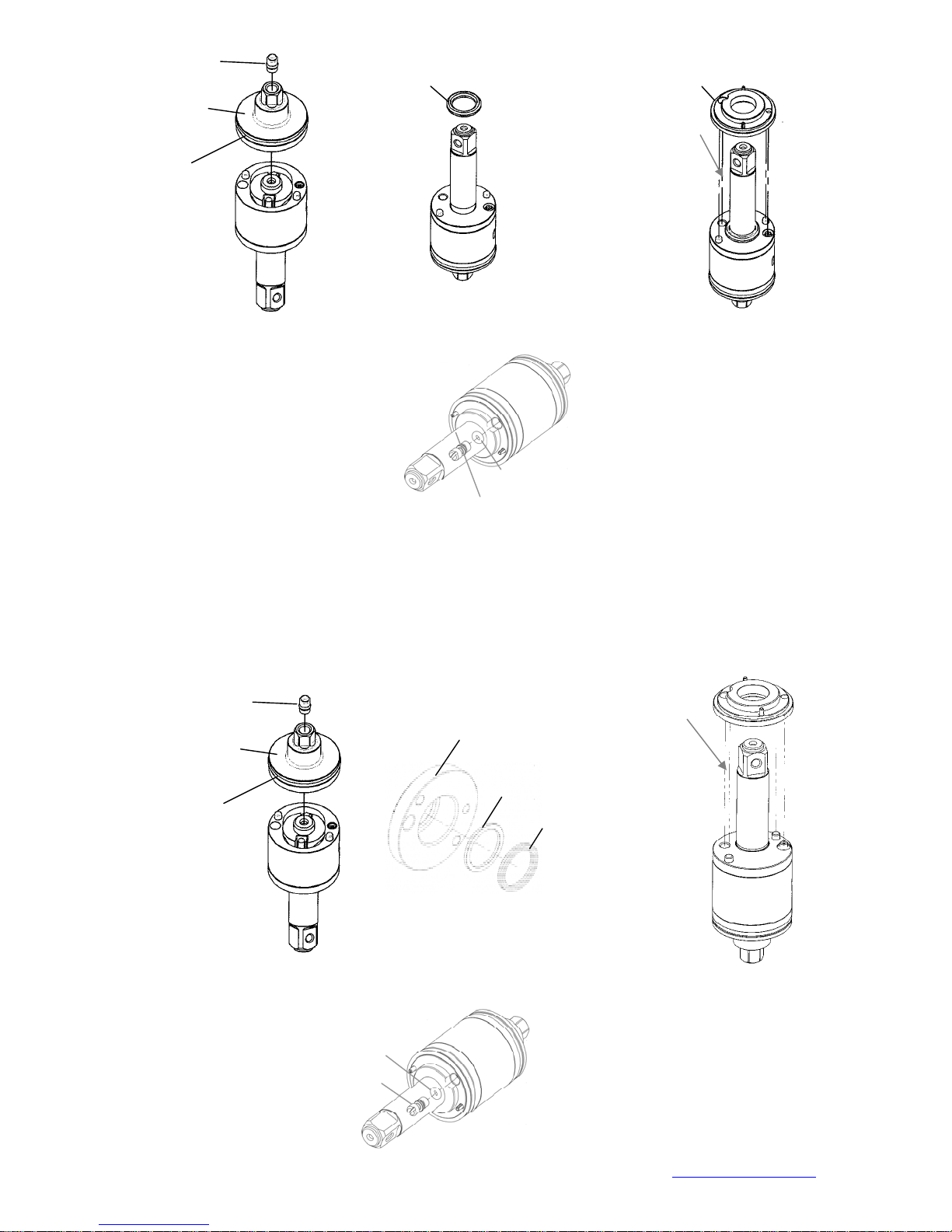
3.1 (a) Install the rear plate to the pulse cylinder and be sure the positions of the pin and the hole are
corresponded. (Fig. 19) Then, plug the pressure valve with the convex facing outside in the hole on the
rear plate.
(b) Put the X-ring on the anvil with the oil applied. (Fig. 20)
(c) Install the front cover to the pulse cylinder by the corresponding positions. (Fig. 21)
Mountz Inc. 1080N 11th Street, San Jose CA 95112 Ph (408) 292-2214 Fax (408) 292-2733 www.mountztorque.com
Press
Fig.17
Fig.18
12
Page 13
Pressure Valve
Rear Plate
O-ring
X-ring
Front Cover
Corresponding position
(a) Fig.19
3.2 After installing the front cover, put the O-ring on the greasing screw, then tighten the greasing screw
but not tighten it completely.
(b) Fig.20
(c) Fig.21
FLEX-70P, FLEX-90P
3.1 (a) Install the rear plate that with the O-ring sleeved (Fig. 23). Make sure the positions of the pin and
hole are exactly matched. Then, plug the pressure valve with the convex facing outside in the hole
on the rear pl ate.
(b) Put the back up ring and the X-ring into the front cover. (Fig. 24)
(c) Install the front cover to the pulse cylinder by the corresponding positions. (Fig. 25)
Pressure Valve
Rear Plate
O-ring
Greasing scr ew
Corresponding position
Front Cover
Fig.22
O-ring
(a) Fig.23
3.2 After installing the front cover, put the O-ring on the greasing screw, then tighten the greasing screw
but not tighten it completely.
Greasing screw
Mountz Inc. 1080N 11th Street, San Jose CA 95112 Ph (408) 292-2214 Fax (408) 292-2733 www.mountztorque.com
O-ring
Back Up Ring
(b) Fig.24
X-ring
(c) Fig.25
Fig.26
13
Page 14
FLEX-100P
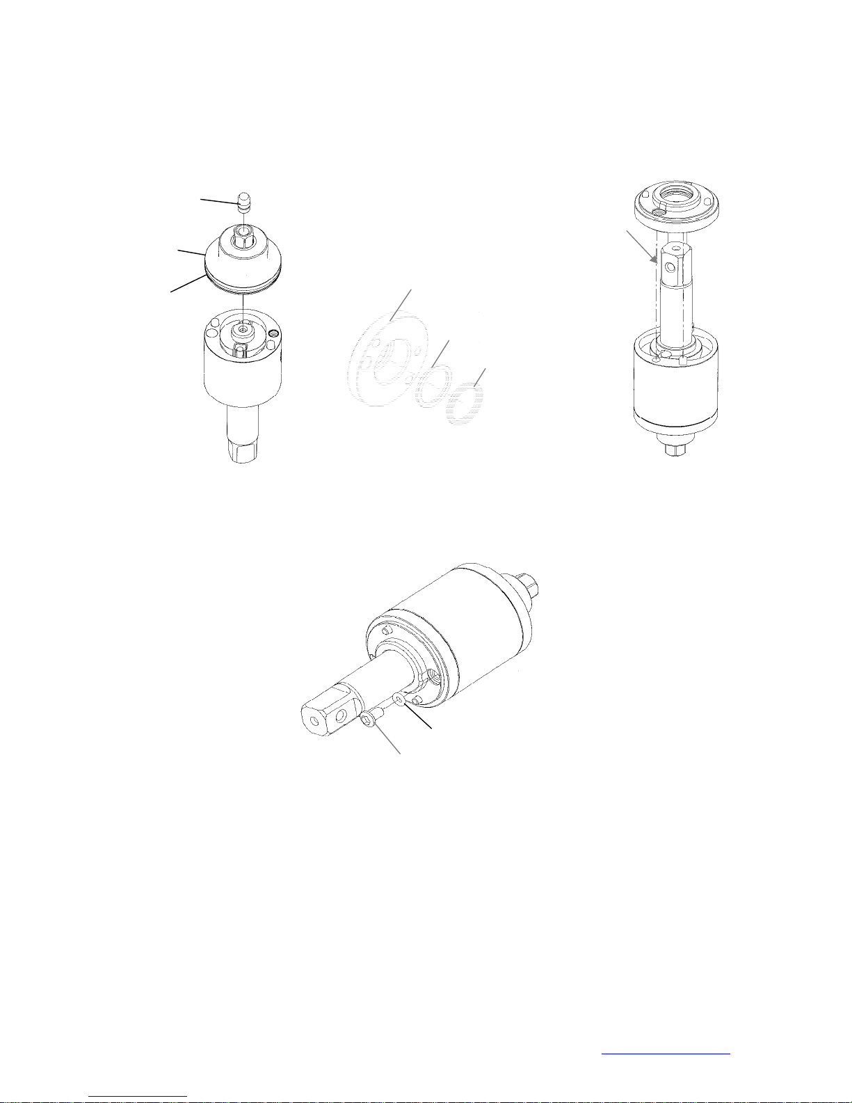
3.1 (a) Install the rear plate that with the O-ring sleeved (Fig. 27). Make sure the positions of the pin and
hole are exactly matched. Then, plug the pressure valve with the convex facing outside in the hole
on the rear plate.
(b) Put the back up ring and the X-ring into the front plate.( Fig. 28)
(c) Install the front cover to the pulse cylinder by the corresponding positions. (Fig. 29)
Pressure Valve
Rear Plate
Corresponding position
O-ring
Front cover
Back up ring
X-ring
(a) Fig. 27
(b) Fig.28
(c) Fig.29
3.2 After installing the front cover, put the O-ring on the greasing screw, then tighten the greasing screw
but not tighten it completely.
O-ring
Greasing screw
Fig.30
FLEX-130P, FLEX-150P
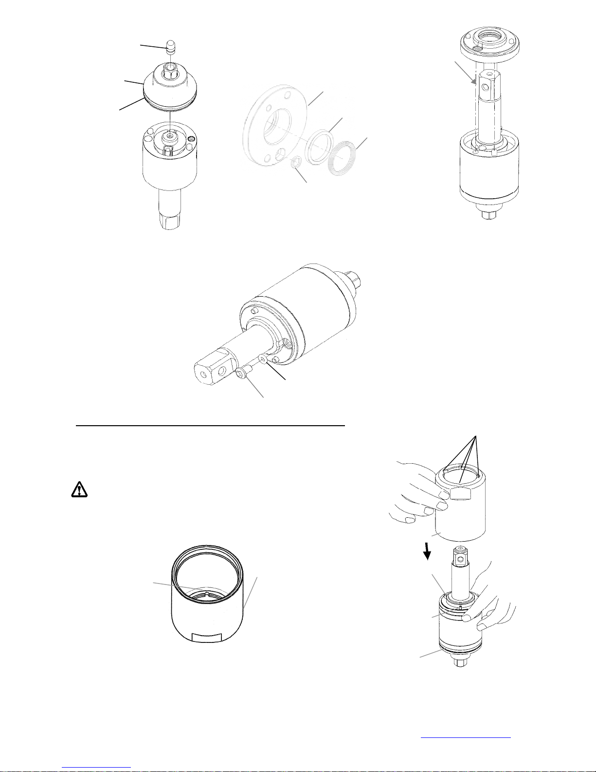
3.1 (a) Install the rear plate that with the O-ring sleeved (Fig. 31). Make sure the positions of the pin
and hole are exactly matched. Then, plug the pressure valve with the convex facing outside in the
hole on the rear plate.
(b) Put the back up rings and the X-ring into the front plate.( Fig. 32)
(c) Install the front cover to the pulse cylinder by the corresponding positions. (Fig. 33).
Mountz Inc. 1080N 11th Street, San Jose CA 95112 Ph (408) 292-2214 Fax (408) 292-2733 www.mountztorque.com
14
Page 15
Pressure Valve
Rear Plate
O-ring
(a) Fig.31
3.2 After installing the front cover, put the O-ring on the greasing screw, then tighten the greasing screw
but not tighten it completely.
4.0 Pulse Cylinder Seat and Lock Nut of Pulse Cylinder Assembly
Greasing scr ew
Back up ring
(b) Fig.32
O-ring
4.1 Place the O-ring inside the bottom of the pulse cylinder seat, then
combine the pulse cylinder seat with the assembled pulse cylinder
unit. (Fig. 35, Fig. 36)
Make sure the half-circle gaps aim at the correspondi n g positions.
Corresponding position
Front cover
Back up ring
X-ring
(c) Fig.33
Fig.34
Half-circle gaps
Pulse Cylinder Seat
O-ring
Pulse Cylinder Seat
Greasing screw
Pin
Fig. 35
O-ring
4.2 Use the appliance to push out the rear plate from the pulse cylinder seat. See Chart 2 in reference to
the proper appliance selection. (Fig. 37)
4.3 Fill up the interior pulse cylinder with the pulse oil about 90% full by a syringe. (Fig. 38)
Mountz Inc. 1080N 11th Street, San Jose CA 95112 Ph (408) 292-2214 Fax (408) 292-2733 www.mountztorque.com
Fig. 36
15
Page 16
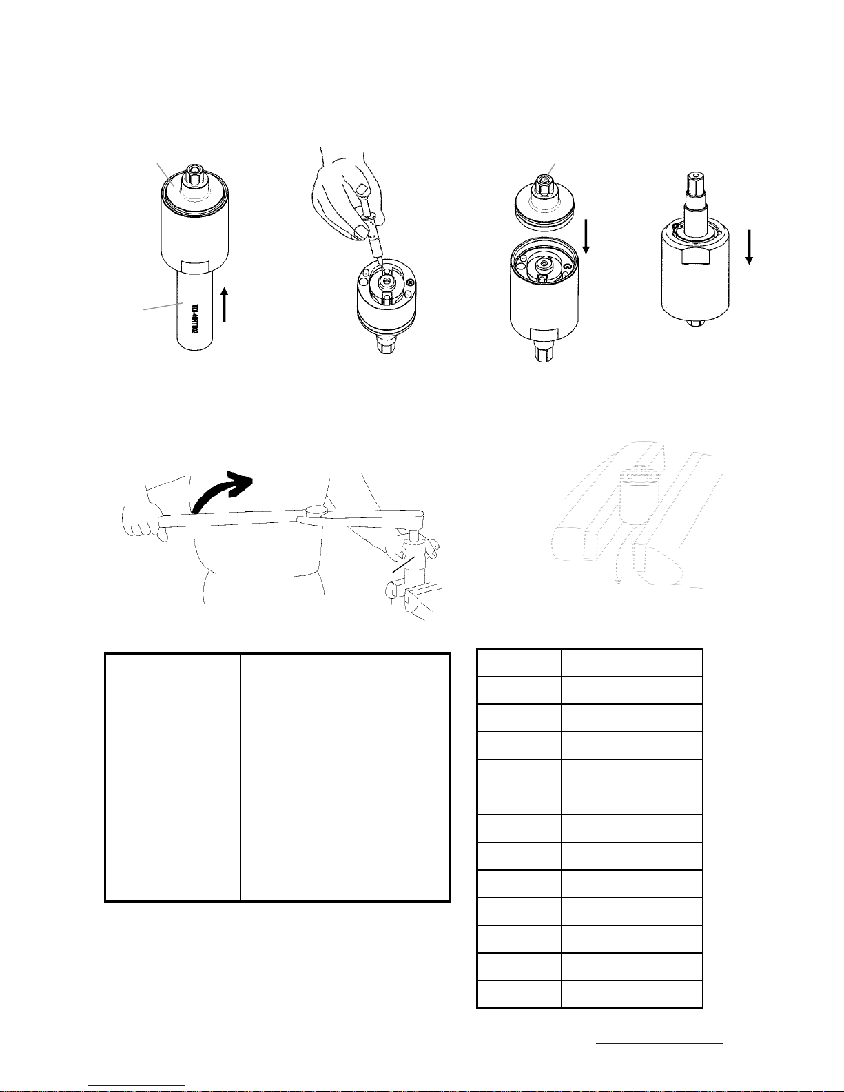
4.4 Install the rear plate taken from the step 2 on the pulse cylinder. Note the corresponding positions
4.5 Turn the assembled unit up side down so the rear plate is at the bottom. Then press the pulse cylinder
seat all the way down to the fixed position. Make sure the corresponding positions are matched
exactly.
Rear Plate Rear Plate
Appliance
4.6 Fix the pulse cylinder seat by a vise. Use an appliance and a torque wrench then turn clockwise to
(Note: Loctite needed when tightening the lock nut of the pulse cylinder)
Chart 3
Appliance No. Apply to
63-TDI-40RT001
Fig.37
Fig.38
tighten the lock nut of the pulse cylinder. See Chart 4 in reference to the proper tightness.
Appliance
FLEX-40P, FLEX-50P,
FLEX-60P,FLEX-30PX ,
FLEX-40PX , FLEX-50PX ,
FLEX-60PX
Fig.39
Fig. 41
Fixed by a vise
Chart 4
Model No. Tighten torque
FLEX-40P 80 N.M
FLEX-50P 80 N.M
FLEX-60P 80 N.M
Fig.40
63-TDI-70RT001 FLEX-70P
63-TDI-90RT001 FLEX-90P
63-TDI-100RT001 FLEX-100P
63-TDI-130RT001 FLEX-130P
63-TDI-150RT001 FLEX-150P
Mountz Inc. 1080N 11th Street, San Jose CA 95112 Ph (408) 292-2214 Fax (408) 292-2733 www.mountztorque.com
FLEX-70P 100 N.M
FLEX-90P 120 N.M
FLEX-100P 140 N.M
FLEX-130P 150 N.M
FLEX-150P 150 N.M
FLEX-30PX 80 N.M
FLEX-40PX 80 N.M
FLEX-50PX 80 N.M
FLEX-60PX 80 N.M
16
Page 17
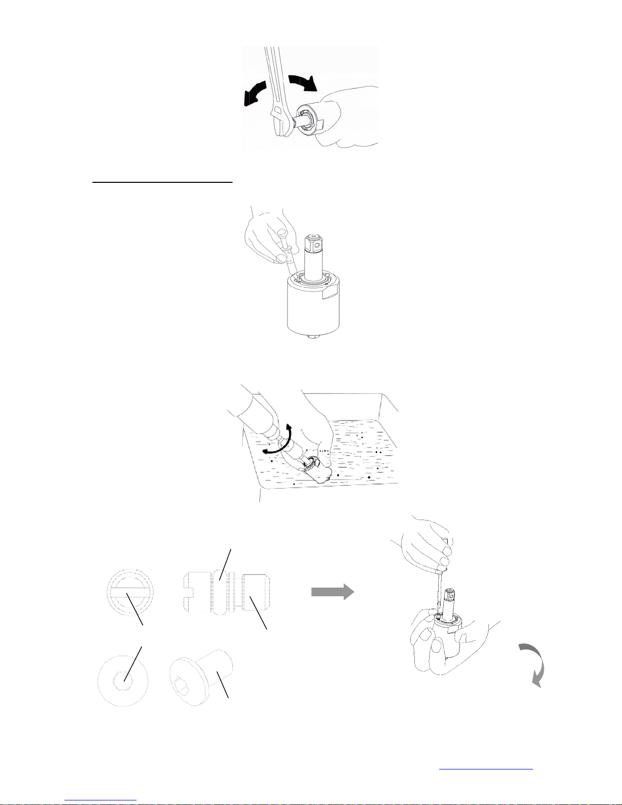
4.7 After completing the above steps, test to make sure the square drive of the anvil rotates freely.
5.0 Steps for Pulse Cylinder Oiling
5.1 Loosen the greasing screw, and inject the authorized oil by a syringe until it is full and overflow.
5.2 Take the unit and dip it in an oil tank, then rotate the anvil by a wrench to release air and the unit
would be full with oil completely.
Fig. 42
Fig. 43
5.3 Use the screwdriver to tighten the greasing screw, Fig. 45.
O-ring
Slotted
Hex
Greasing
Screw
Fig. 45
Mountz Inc. 1080N 11th Street, San Jose CA 95112 Ph (408) 292-2214 Fax (408) 292-2733 www.mountztorque.com
Greasing Screw
( for FLEX-100P/FLEX-130P)
Fig. 44
17
Page 18
r
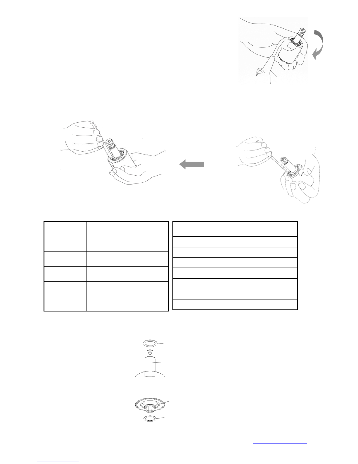
5.4 Use an air spray gun to blow off the oil on the cylinder seat, Fig. 46.
Fig. 46
5.5 Loosen the greasing screw again an d use a sy ringe to draw out a little amount of oil ( see Chart 5) .
Finally, tighten the greasing screw back to the pulse cylinder unit, Fig.47
Fig. 47
Chart 5
Model No. Amount of oil draw
Model No. Amount of oil draw
FLEX-40P
FLEX-50P
FLEX-60P
FLEX-70P
0.25 CC
0.4 CC
0.5 CC
0.6 CC
FLEX-100P 1.2 CC
FLEX-130P 1.2 CC
FLEX-150P 1.2 CC
FLEX-30PX 0.2 CC
FLEX-40PX 0.25 CC
FLEX-50PX 0.4 CC
FLEX-90P
6.0 Torque Testing
0.7 CC
FLEX-60PX 0.5 CC
6.1 Put the washer on the front end of the anvil, and then put another washer on the rear plate.
Washe
Anvil
Rear
Fig.48
Mountz Inc. 1080N 11th Street, San Jose CA 95112 Ph (408) 292-2214 Fax (408) 292-2733 www.mountztorque.com
18
Page 19
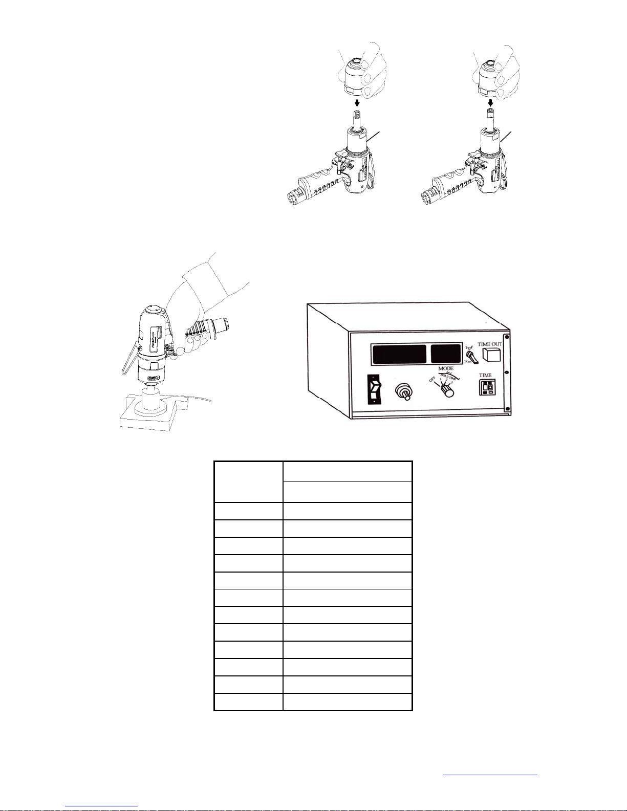
6.2 Tighten the clutch housing by hands.
r
Wrench
Fig.4
6.3 Test the forward torque by a digital torque tester and make sure the tool pulses smoothly.
Digital Torque Teste
Fig. 50
Model No.
FLEX-40P
FLEX-50P
FLEX-60P
FLEX-70P
FLEX-90P
FLEX-100P
FLEX-130P
FLEX-150P
FLEX-30PX
FLEX-40PX
FLEX-50PX
FLEX-60PX
Air inlet pressure 85 PSI
N.M (at least)
15.5
25
35
55
90
125
145
210
12.5
14
22
28
Chart 6
Mountz Inc. 1080N 11th Street, San Jose CA 95112 Ph (408) 292-2214 Fax (408) 292-2733 www.mountztorque.com
Driver
19
Page 20
6.4 If the test result is NG (see Chart 6 in reference to the torque standard), MUST draw out or add a little
A
App
mount of oil and do the following steps:
6.4.1 Loosen the pulse unit housing by hands.
6.4.2 Loosen the greasing screw.
6.4.3 Draw out or add a little amount of oil.
6.4.4 Tighten the greasing screw back.
6.4.5 Tighten the pulse unit housing.
6.4.6 Test the torque again. If the test result is still NG, repeat the Steps 6.4.1 to 6.4.5 until the
desired torque is reached.
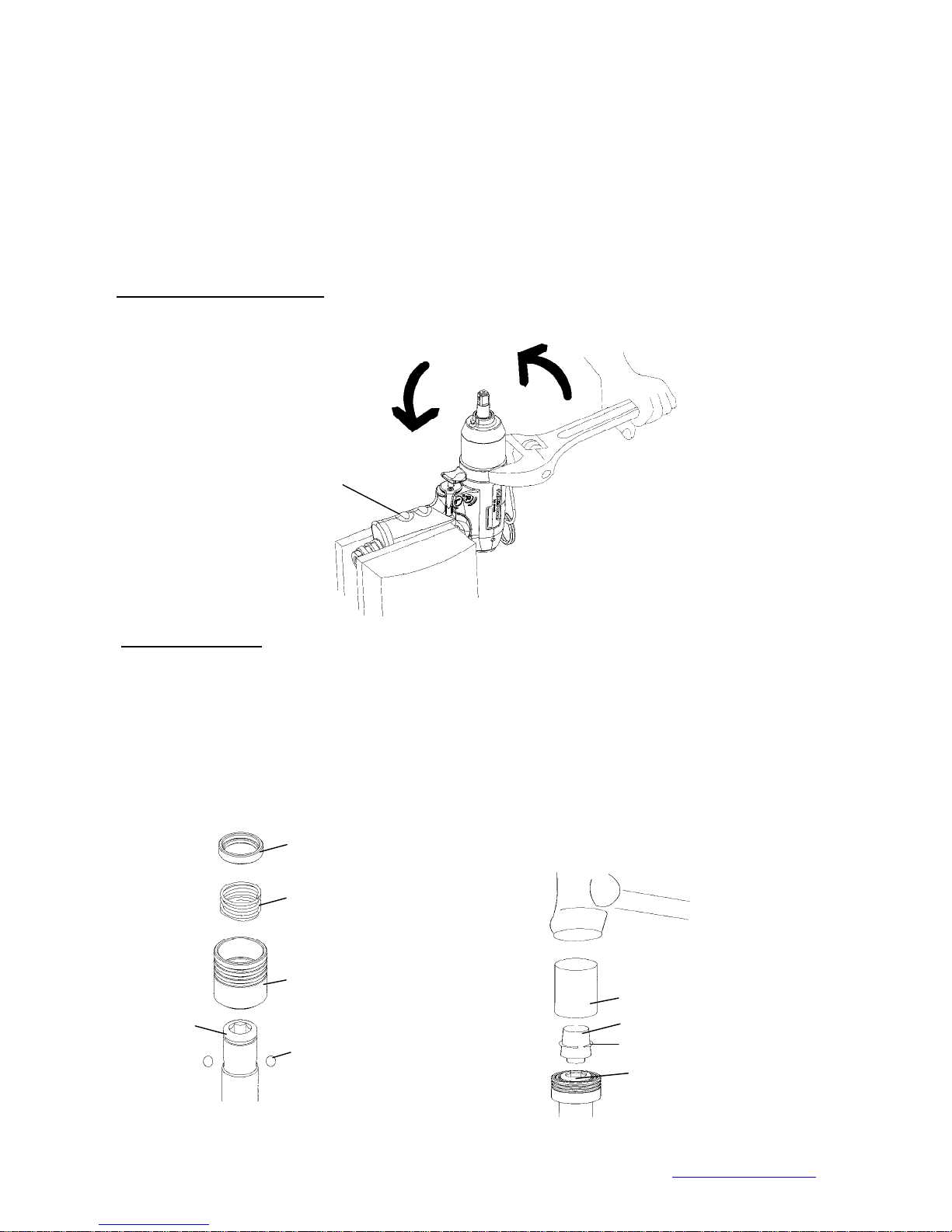
7.0 Pulse Unit Housing Assembly
Fix the housing by a vise. Turn the wrench in counter clockwise direction to tighten the pulse unit housing.
Note: Handle rubber must
be covered by a piece of
cloth to avoid damage
Fig. 51
8.0 Anvil Unit Assembly
: (for FLEX-30PX, FLEX-40PX, FLEX-50PX, and FLEX-60PX)
(a) Place the steel ball, the quick change holder, the spring, and the hold spacer orderly as Fig. 52 showed.
(b) Put the anvil collar on the Appliance # 63-TDI-40RT006. See Fig. 53.
(c) Place the 63-TDI-40RT006 on the hex-hole of the anvil, then put the Appliance # 63-TDI-40RT005 on the
63-TDI-40RT006 and taps it making sure the anvil collar sleeves into the anvil at proper position. See Fig.
53.
Hold Spacer
Spring
Quick Change Holder
Anvil
Steel Ball
Mountz Inc. 1080N 11th Street, San Jose CA 95112 Ph (408) 292-2214 Fax (408) 292-2733 www.mountztorque.com
Fig.52
Appliance 63-TDI-40RT005
liance 63-TDI-40RT006
nvil Collar
Hex- hole of Anvil
Fig. 53
20
Page 21
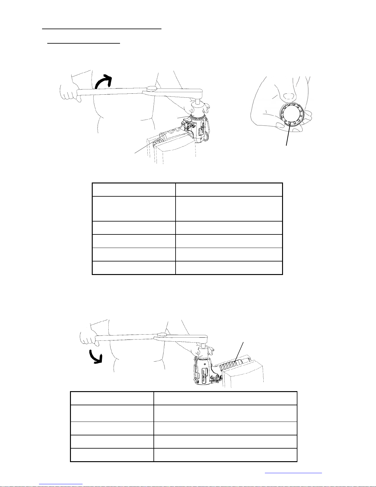
HOUSING AND MOTOR SET DISASSEMBLY:
App
1.0 Cylinder Unit Disassem b l y
1.1 Take a piece of cloth to cover the housing handle and fix the tool with a vise. Use the appliance
(see Chart 7) to take the lock nut out of cylinder by turning clockwise.
Note: Handle rubber must
be covered by a piece of
cloth to avoid damage
:
Appliance
Appliance No. Apply to
FLEX-40P, FLEX-50P, FLEX-60P,
63-TDI-40RT004
FLEX-30PX ,FLEX-40PX ,
FLEX-50PX ,FLEX-60PX
Fig. 54
Lock Nut of Cylinder
1.2 Fix the housing in an opposite position. Use the appliance to loosen the lock nut of rear plate of cylinder
63-TDI-90RT003 FLEX-70P、FLEX-90P
63-TDI-100RT003 FLEX-100P
63-TDI-130RT003 FLEX-130P
63-TDI-150RT003 FLEX-150P
Chart 7
in counter clockwise direction.
Appliance No. Apply to
63-TDI-40RT003
63-TDI-100RT002 FLEX-70P, FLEX-90P, FLEX-100P
63-TDI-130RT002 FLEX-130P
63-TDI-150RT002 FLEX-150P
Mountz Inc. 1080N 11th Street, San Jose CA 95112 Ph (408) 292-2214 Fax (408) 292-2733 www.mountztorque.com
Note: Handle rubber must
be covered by a piece of
cloth to avoid damage
liance
Fig. 55
FLEX-40P, FLEX-50P, FLEX-60P, FLEX-30PX ,
FLEX-40PX , FLEX-50PX , FLEX-60PX
21
Page 22
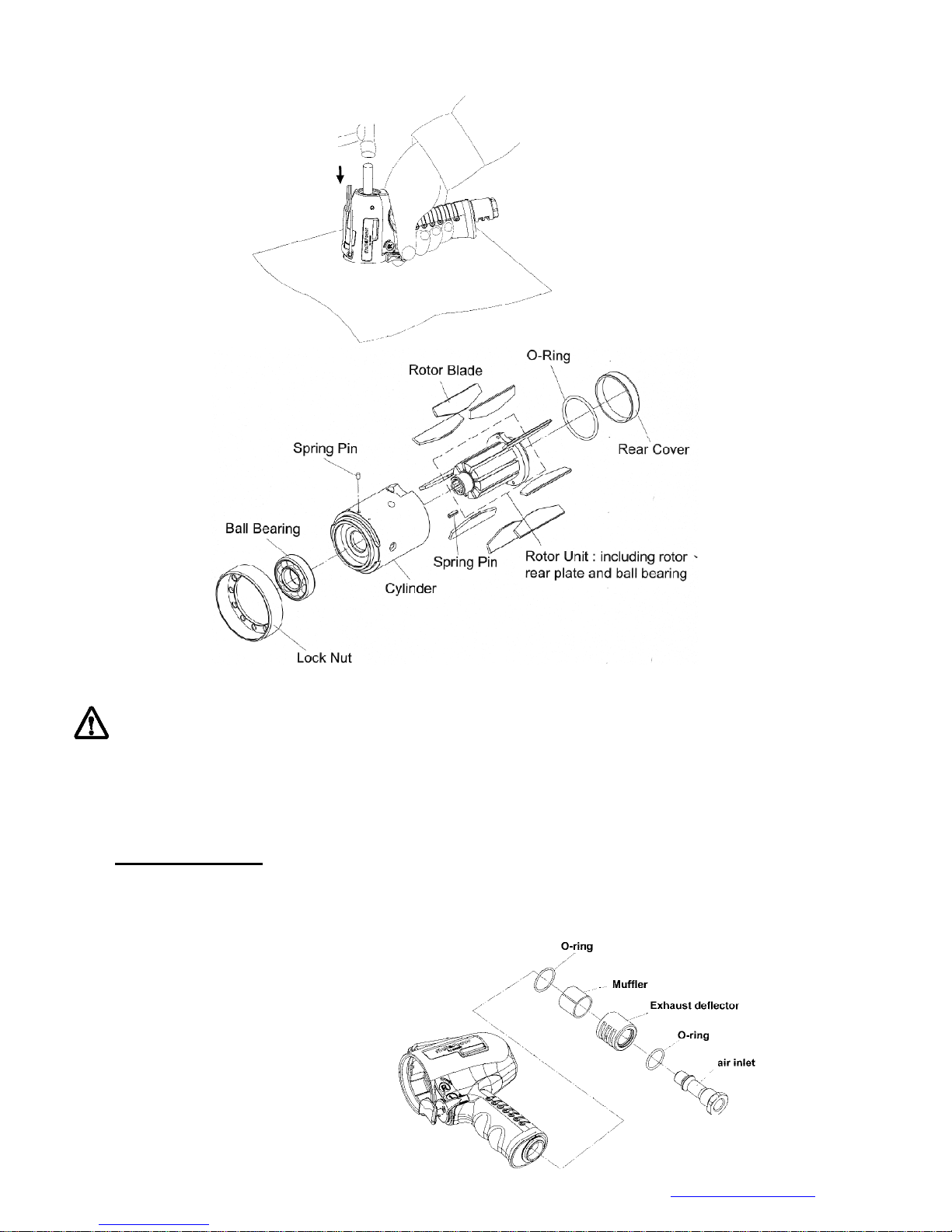
1.3 Take a piece of cloth and lay it on a Chart before disassembly. Hold the housing and tap
slightly with a plastic stick to push the cylinder unit out.
1.4 Parts of Motor Set:
Fig.56
Fig. 57
The rotor and the rear end plate must be press fit. The clearance of the two parts must be in between 0.01~
0.02 mm. It would not be easy to assemble the two parts by repair centers in general. Therefore, as there is a
need of repair on the parts of the rotor, the rear end plate, and the ball bearing, we strongly suggest
replacing a complete ROTOR UNIT, which is including the rotor, the rear plate, and the ball bearing. The rotor
unit would be full assembled and well-measured before delivery.
3.0 Air Inlet Disassembly
:
Take the air inlet unit apart from the end of the housing. The parts of O-ring, Muffler, Exhaust deflector
are separated by each other
.
Mountz Inc. 1080N 11th Street, San Jose CA 95112 Ph (408) 292-2214 Fax (408) 292-2733 www.mountztorque.com
Fig.58
22
Page 23
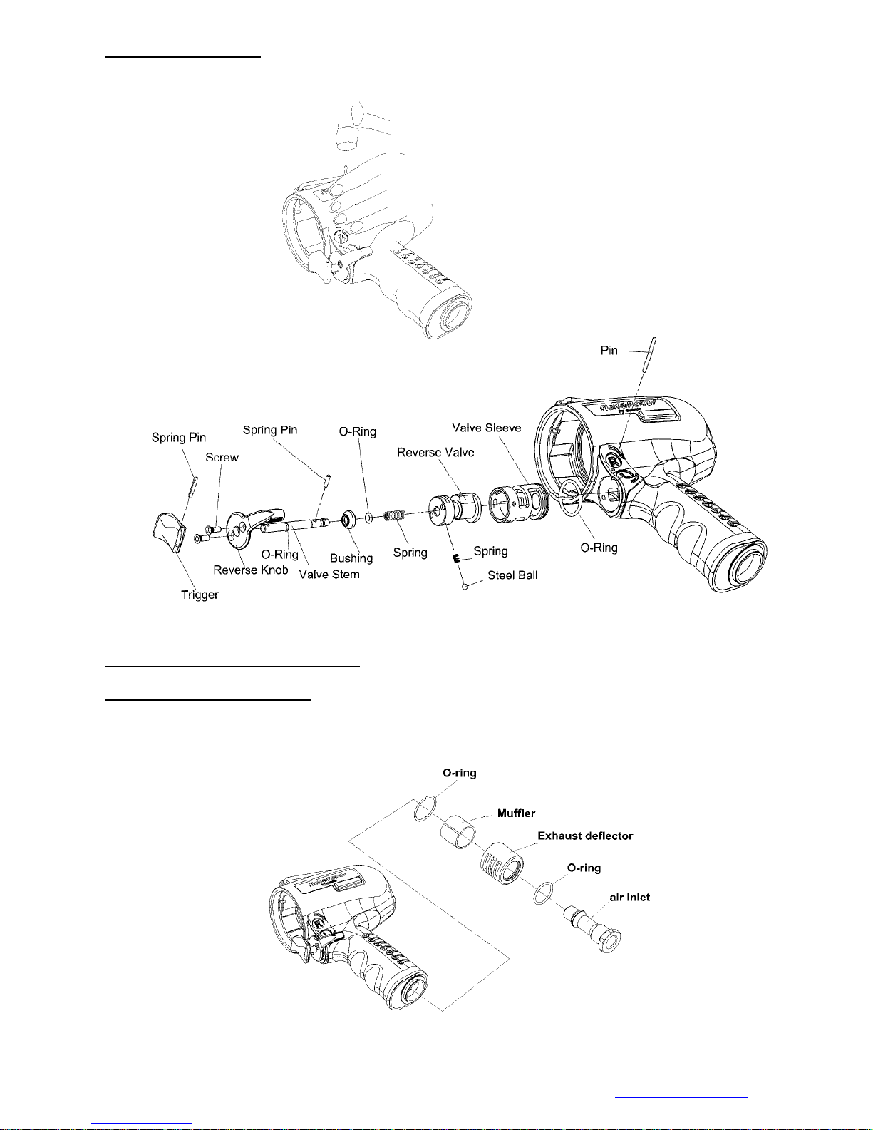
3. Trigger Set D isassembly:
Remove the pin to take apart the valve sleeve set. All the parts are disassembled as the below drawing
showed.
Fig. 59
HOUSING AND MOTOR SET ASSEMBL Y:
1. Hous ing and Air Inlet Assembly:
Install and tighten the parts of air inlet one by one and orderly. (NOTE: Apply the Loctite on the
threads of air inlet before assembly)
Mountz Inc. 1080N 11th Street, San Jose CA 95112 Ph (408) 292-2214 Fax (408) 292-2733 www.mountztorque.com
Fig. 60
23
Page 24
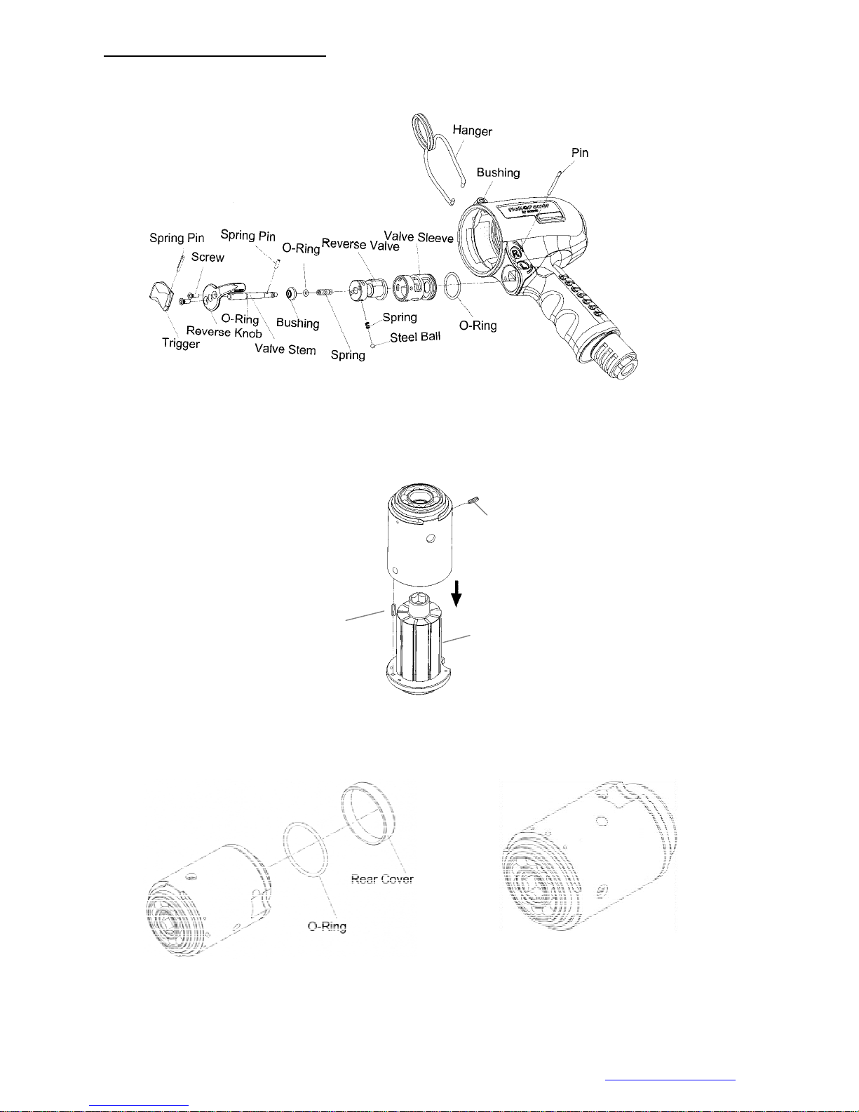
2. Housing and Trigger Set Assembly:
Install the parts of the trigger set orderly (see Fig. 61 drawing for reference). Then, insert the pin to fix
all the parts. And, install the hanger to complete the assembly.
3.0 Cylinder Unit Assembly
3.1 Place the rotor blades into the rotor. Insert the spring pin A and B into the cylinder. Make sure the
pins aim at the pin holes when putting the cylinder down.
Fig. 61
Spring pin B
Spring pin A
3.2 Install the O-ring and the rear cover to the rear plate. The motor set assembly is complete.
Rotor unit
Fig. 62
Fig. 63
Mountz Inc. 1080N 11th Street, San Jose CA 95112 Ph (408) 292-2214 Fax (408) 292-2733 www.mountztorque.com
24
Page 25
4.0 Housing and Motor Set Assembly
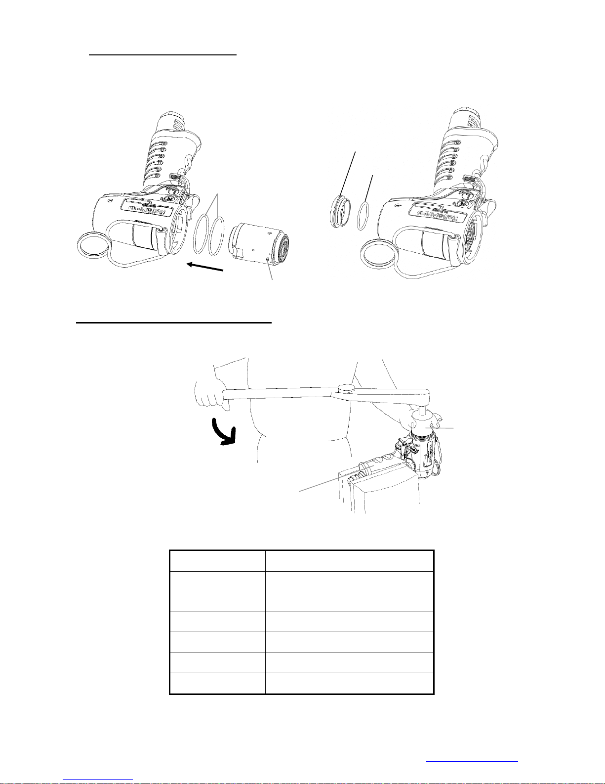
Place two O-rings into the housing, then the motor set. Be sure the direction is correct when putting the
motor set in, i.e. the pin on the side cylinder must aim at the hole to fix position as Fig. 64 showed. Finally,
place the O-ring and the lock nut of the rear cover, Fig.65 to complete the assembly.
O-rings
Lock Nut of Rear
O-ring
Fig.64
Spring pin
Fig. 65
5.0 Housing and Lock Nut of Cylinder Assembly
Fix the tool by a vise. Place the lock nut of the cylinder nut and t ighten by the appliance in counter c lockwise
direction. Assembly i s complete. See the Chart 9 and 10 in reference to appliance use and tighten torque.
Appliance
Note: Handle rubber must
be covered by a piece of
cloth to avoid damage
Fig. 66
Appliance No. Apply to
FLEX-40P, FLEX-50P, FLEX-60P,
63-TDI-40RT004
63-TDI-90RT003 FLEX-70P, FLEX-90P
63-TDI-100RT003 FLEX-100P
63-TDI-130RT003 FLEX-130P
63-TDI-150RT003 FLEX-150P
FLEX-30PX ,FLEX-40PX ,
FLEX-50PX , FLEX-60PX
Mountz Inc. 1080N 11th Street, San Jose CA 95112 Ph (408) 292-2214 Fax (408) 292-2733 www.mountztorque.com
Chart 9
26
Page 26
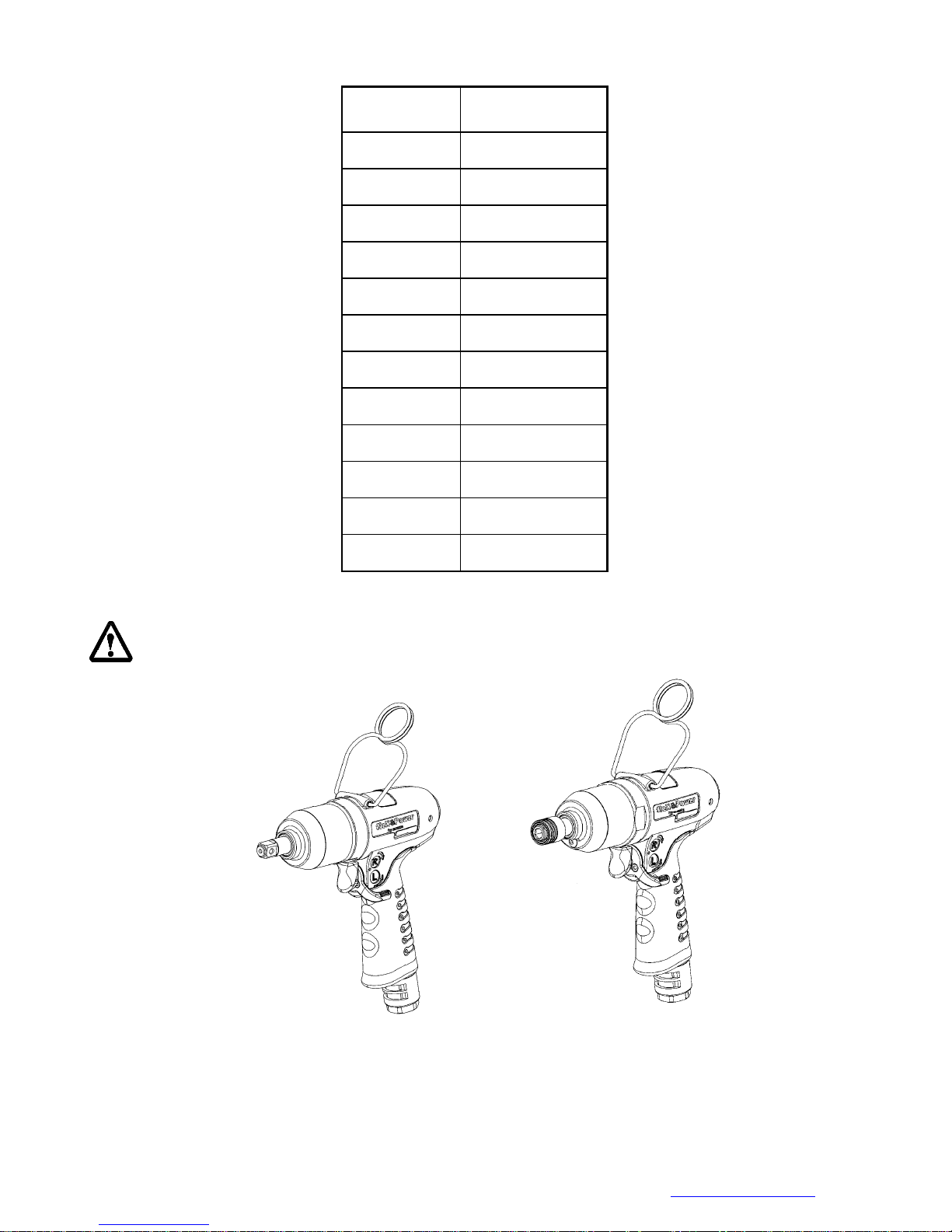
Model No. Tighten torque
FLEX-40P
FLEX-50P
FLEX-60P
FLEX-70P
FLEX-90P
FLEX-100P
FLEX-130P
FLEX-150P
FLEX-30PX
FLEX-40PX
FLEX-50PX
FLEX-60PX
Chart 10
After all the assembly is complete, test to make sure the anvil rotates freely, then connect the air hose
and test the torque.
40 N.M
40 N.M
40 N.M
60 N.M
60 N.M
60 N.M
60 N.M
60 N.M
40 N.M
40 N.M
40 N.M
40 N.M
Fig.67
Mountz Inc. 1080N 11th Street, San Jose CA 95112 Ph (408) 292-2214 Fax (408) 292-2733 www.mountztorque.com
26
Page 27
Y /
DISASSEMBL
FLEXS-40P, FLEXS-50P, FLEXS-60P, FLEXS-70P, FLEXS-90P, FLEXS-100P, FLEXS-130P, FLEXS-150P
FLEX-30PX, FLEXS-40PX, FLEXS-50PX, FLEXS-60PX
ASSEMBLY FOR PULSE WRENCHES
PULSE MECHANISM DISASSEMBLY
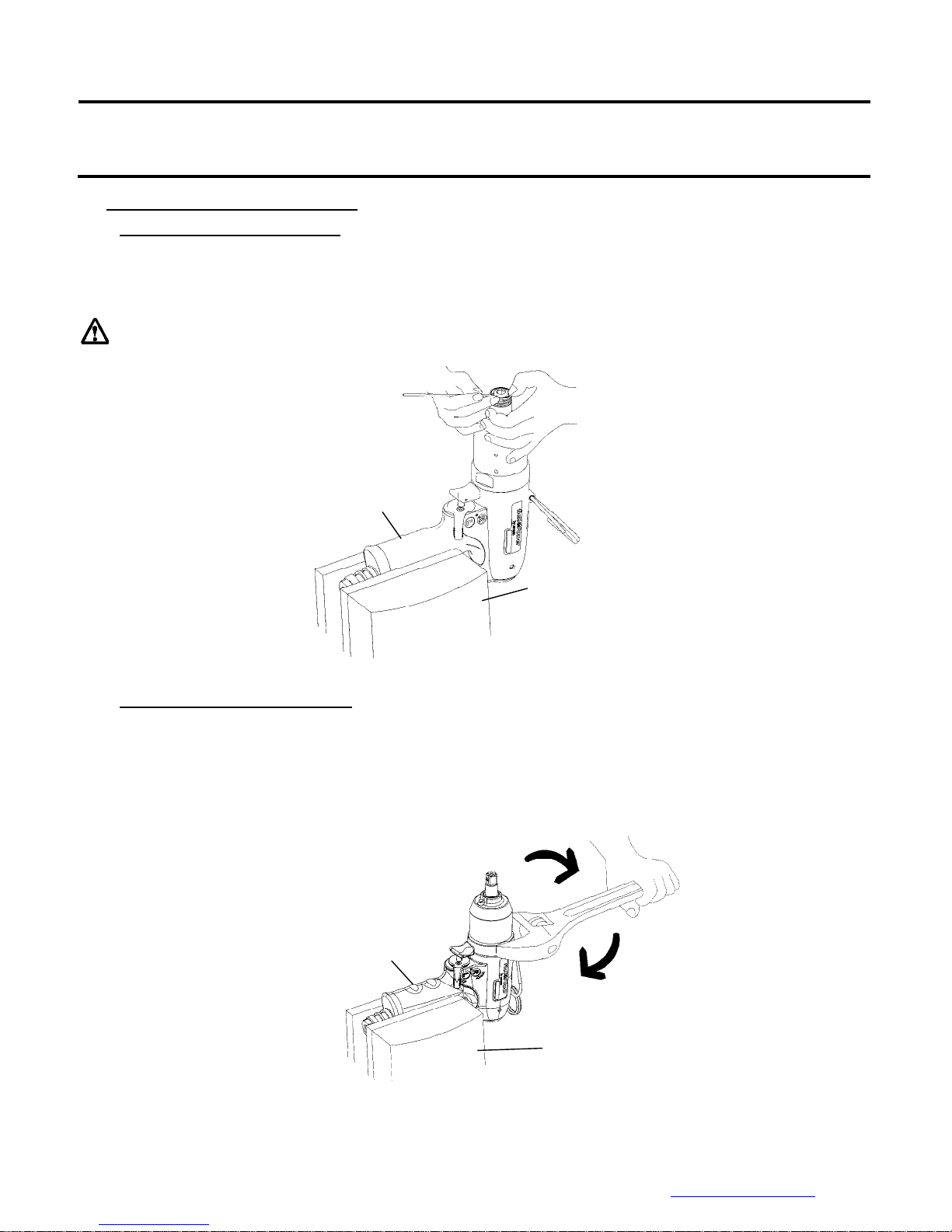
1.0 Quick Change Holder Assembly
Press down the hold spacer, and find the anvil collar. Use the a needle like stuff to get the anvil
collar out, then take the quick change holder, the hold spacer, the spring, and the steel ball apart.
The steel ball may drop off when taking out the Quick Change Holder
Note: Handle rubber must be
covered by a piece of cloth to
avoid damage
: (for Model No. FLEX-30PX, FLEXS-40PX, FLEXS-50PX, FLEXS-60PX)
2.0 Pulse Unit Housing Disassembly:
Fix the tool by a vise, use an adjusChart wrench clockwise to loosen the pulse unit housing until
the pulse unit housing detach from the motor housing. Then, take the pulse unit out, Fig 69.
Note: Handle rubber must be
covered by a piece of cloth to
avoid damage
Vise
Fig.68
Vise
Mountz Inc. 1080N 11th Street, San Jose CA 95112 Ph (408) 292-2214 Fax (408) 292-2733 www.mountztorque.com
Fig.69
27
Page 28
3.0 Pulse Unit Disassembly:
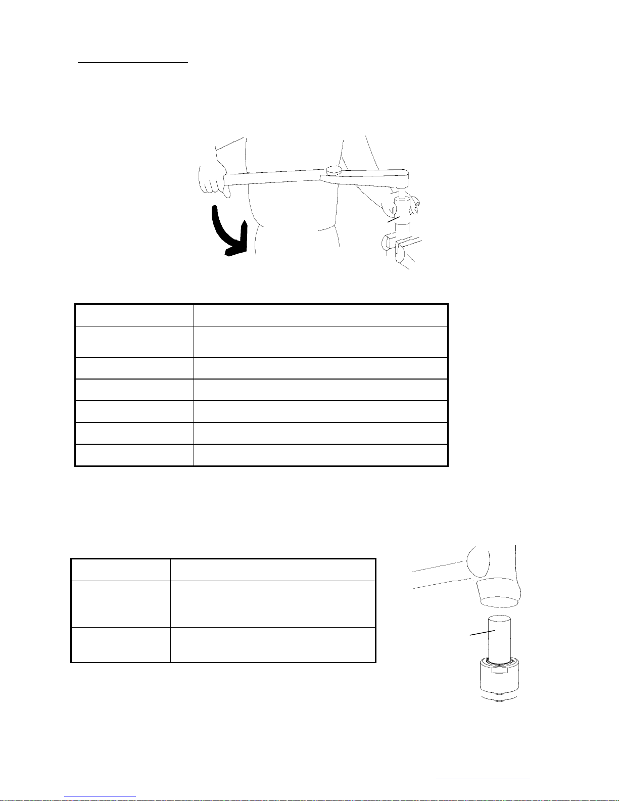
3.1 Fix the pulse unit by a vise. Use the appliance (see Chart 11) to loosen the lock nut on the pulse
unit, Fig. 70.
Note: Loctite was applied on the lock nut when tools assembled.
Appliance No. Apply to
63-TDI-40RT001
63-TDI-70RT001 FLEXS-70P
63-TDI-90RT001 FLEXS-90P
63-TDI-100RT001 FLEXS-100P
63-TDI-130RT001 FLEXS-130P
63-TDI-150RT001 FLEXS-150P
3.2 Put the Appliance, see Chart 12, on the anvil and tap on it slightly to detach the interior parts from the
pulse unit, Fig. 71.
Appliance
FLEXS-40P, FLEXS-50P, FLEXS-60P, FLEX-30PX ,
FLEXS-40PX , FLEXS-50PX , FLEXS-60PX
Chart 11
Fig. 70
Appliance No. Apply to
FLEXS-40P, FLEXS-50P, FLEXS-60P,
63-TDI-40RT002
63-TDI-90RT002
FLEXS-70P,FLEX-30PX ,FLEXS-40PX ,
FLEXS-50PX , FLEXS- 60PX
FLEXS-90P, FLEXS-100P, FLEXS-130P,
FLEXS-150P
Chart 12
Mountz Inc. 1080N 11th Street, San Jose CA 95112 Ph (408) 292-2214 Fax (408) 292-2733 www.mountztorque.com
Appliance
Appliance
Fig. 71
28
Page 29
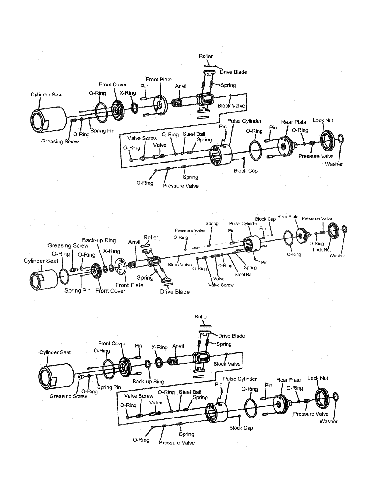
3.4 Parts of Pulse Cylinder Unit:
a. FLEXS-40P, FLEXS-50P, FLEXS-60P
b. FLEXS-70P, FLEXS-90P
c. FLEXS-100P
Mountz Inc. 1080N 11th Street, San Jose CA 95112 Ph (408) 292-2214 Fax (408) 292-2733 www.mountztorque.com
29
Page 30
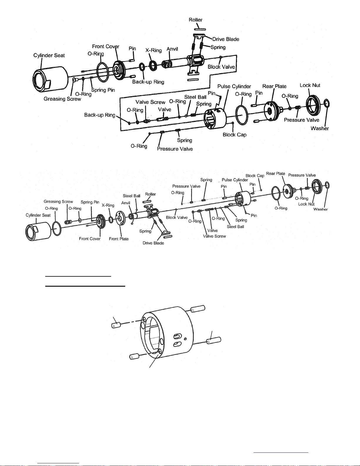
d. FLEXS-130P
e. FLEX-30PX ,FLEXS-40PX , FLEXS-50PX , FLEXS-60PX
PULSE UNIT ASSEMBLY:
1.0 Pulse Cylinder Unit Assembly:
1.1 Install the pins on both sides of the pulse cylinder. (Fig. 72)
Pin
Pin
Pulse Cylinder
Fig.72
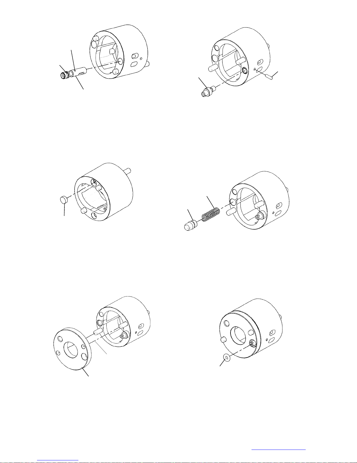
1.2 Sleeve the O-ring to the valve and install the valve into the big hole on the pulse cylinder. (Step 1;
Fig.73)
1.3 Insert the pin into the hole on the side of the pulse cylinder. (Step 2; Fig.74)
1.4 Screw the valve screw to the pressure valve. (Step 3; Fig.74)
NOTE: the valve screw MUST screw to the most bottom position certainly.
Mountz Inc. 1080N 11th Street, San Jose CA 95112 Ph (408) 292-2214 Fax (408) 292-2733 www.mountztorque.com
30
Page 31
Small hole
O-ring
Big hole
Step 1; Fig.73
Valve screw
Step 2; Fig.74
Pin
1.5 Plug the block cap into the hole and make sure it is parallel to the surface of the pulse cylinder.
(Step 4; Fig. 75)
1.6
(Step 5; Fig. 76)
Put the spring into the hole then install the pressu re valve that with th e 0-ring sleeved.
Spring
Pressure Valve
Block Cap
Step 4; Fig.75
Step 5; Fig.76
1.7 Install the front plate and make sure the corresponding position with the pins. (Step 6; Fig. 77)
1.8 Sleeve the O-ring on the valve screw and press into the hole. Make sure it is parallel to the surface of the
front plate. (Step 7; Fig. 78)
Front Plate
Corresponding position
Step 6; Fig.77
O-ring
Step 7; Fig.78
Mountz Inc. 1080N 11th Street, San Jose CA 95112 Ph (408) 292-2214 Fax (408) 292-2733 www.mountztorque.com 31
Page 32
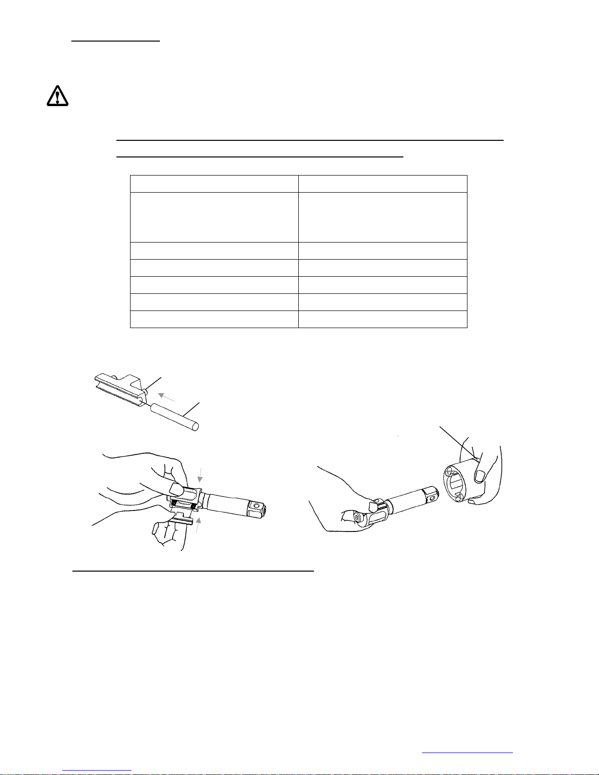
2.0 Anvil Unit Assembly
Install the roller to the drive blade, then insert the springs into the anvil and press the blades from both
sides. Finally put the anvil to the pulse cylinder to complete the anvil unit assembly.
MUST follow the direction as Fig.81 showed while installing the anvil unit into the pulse cylinder; be sure
to aim at the highest points by two sides of the interior pulse unit and press the two drive blades in slowly.
NOTE: RECOMMENDED UTILIZE THE SPECIAL FIXTURE FOR EASIER INSTALLATI ON FOR THE
ANVIL WITH THE ROLLER AND THE BLADE INTO THE CYLINDER
(No picture showed)
FIXTURE PAR T No TOOL MODEL
63-I40AST-001K FLEXS-40P, FLEXS-50P, FLEXS-60P,
FLEXS-40PX, FLEXS-50PX,
FLEXS-60PX,
63-I70AST-001K FLEXS-70P
63-I90AST-001K FLEXS-90P
63-I100AST-001K FLEXS-100P
63-I130AST-001K FLEXS-130P
63-I150AST-001K FLEXS-150P
Drive Blade
Roller
Front Plate
Fig.79
Press
Press
Fig.80
Fig.81
3.0 Front Cover and Rear Plate of Pulse Cylinder Assembly (For the models: FLEXS-40P, FLEXS-50P, FLEXS-60P,
FLEX-30PX ,FLEXS-40PX , FLEXS-50PX , FLEXS-60PX)
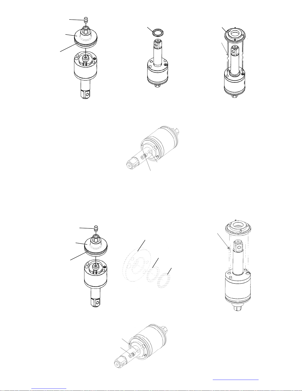
3.1 (a) Install the rear plate to the pulse cylinder and be sure the positions of the pin and the hole are
corresponded. (Fig. 82) Then, plug the pressure valve with the convex facing outside in the hole
on the rear plate.
(b) Put the X-ring on the anvil with the oil applied. (Fig. 83)
(c) Install the front cover to the pulse cylinder by the corresponding positions. (Fig. 84)
Mountz Inc. 1080N 11th Street, San Jose CA 95112 Ph (408) 292-2214 Fax (408) 292-2733 www.mountztorque.com
32
Page 33
Pressure Valve
Rear Plate
O-ring
X-ring
Front Cover
Corresponding position
(a) Fig.82
(b) Fig.83
(c) Fig.84
3.2 After installing the front cover, put the O-ring on the greasing screw, then tighten the greasing screw but
not tighten it completely.
FLEXS-70P, FLEXS-90P
3.1
(a) Install the rear plate that with the O-ring sleeved (Fig. 86). Make sure the positions of the pin
and hole are exactly matched. Then, plug the pressure valve with the convex facing outside in t
he hole on the rear plate.
(b) Put the back up ring and the X-ring into the front cover. (Fig. 87)
(c) Install the front cover to the pulse cylinder by the corresponding positions. (Fig. 88)
Pressure Valve
Rear Plate
O-ring
Greasing screw
Corresponding position
Front Cover
Fig.85
O-ring
3.2 After installing the front cover, put the O-ring on the greasing screw, then tighten the greasing screw
(a) Fig.86
but not tighten it completely.
Greasing screw
Mountz Inc. 1080N 11th Street, San Jose CA 95112 Ph (408) 292-2214 Fax (408) 292-2733 www.mountztorque.com
O-ring
Back Up Ring
(b) Fig.87
X-ring
(c) Fig.88
Fig.89
33
Page 34
FLEXS-100P
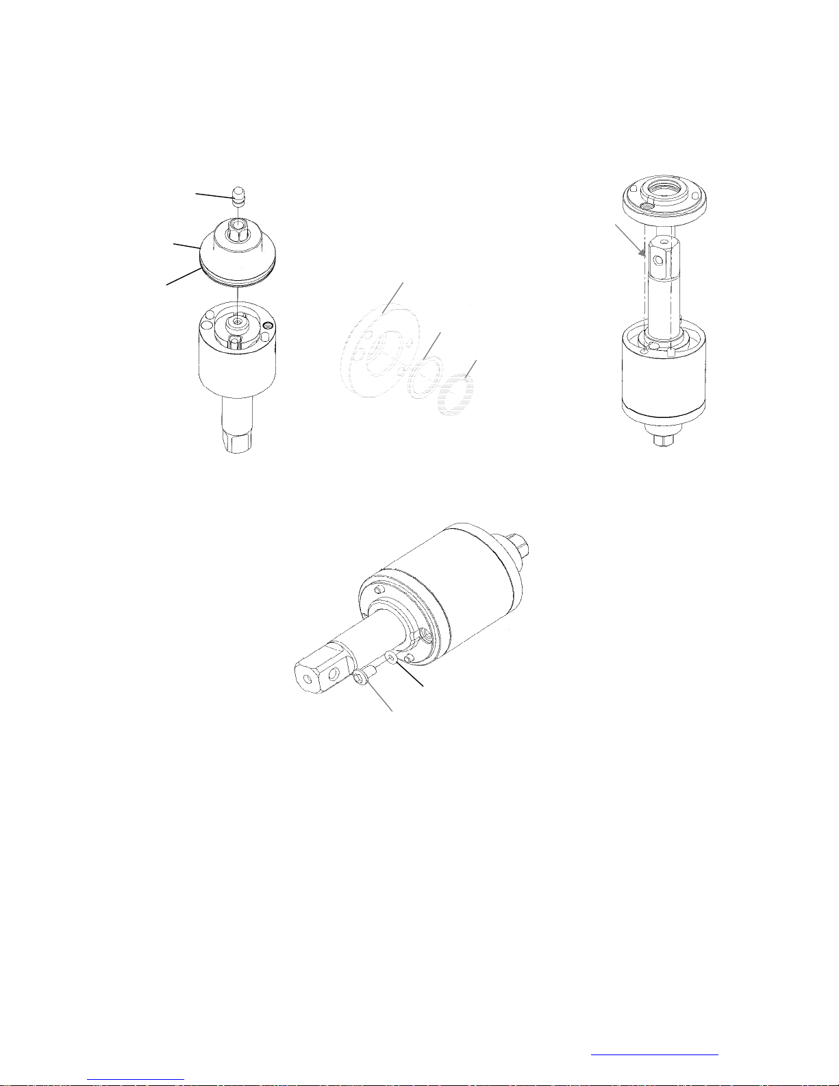
3.1 (a) Install the rear plate that with the O-ring sleeved (Fig. 90). Make sure the positions of the pin
and hole are exactly matched. Then, plug the pressure valve with the convex facing outside in
the hole on the rear plate.
(b) Put the back up ring and the X-ring into the front plate. ( Fig. 91)
(c) Install the front cover to the pulse cylinder by the corresponding positions. (Fig. 92)
Pressure Valve
Rear Plate
Corresponding position
O-ring
Front cover
Back up ring
X-ring
(b) Fig.91
(a) Fig. 90
(c) Fig.92
3.2 After installing the front cover, put the O-ring on the greasing screw, then tighten the greasing
scr ew but not tighten it completely.
O-ring
Greasing screw
Fig.93
FLEXS-130P
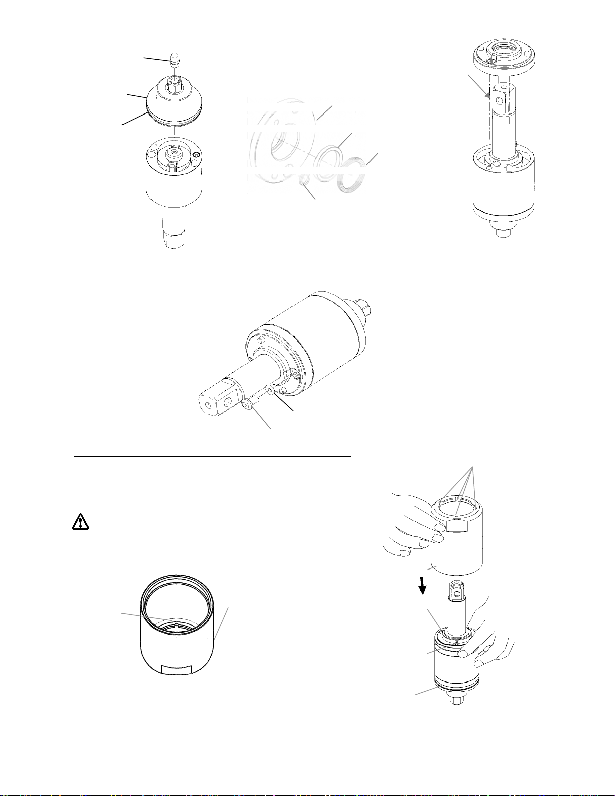
3.1 (a) Install the rear plate that with the O-ring sleeved (Fig. 94). Make sure the positions of the pin
and hole are exactly matched. Then, plug the pressure valve with the convex facing outside in
the hole on the rear plate.
(b) Put the back up rings and the X-ring into the front plate.( Fig. 95)
(c) Install the front cover to the pulse cylinder by the corresponding positions. (Fig. 96).
Mountz Inc. 1080N 11th Street, San Jose CA 95112 Ph (408) 292-2214 Fax (408) 292-2733 www.mountztorque.com
34
Page 35
Pressure Valve
Rear Plate
O-ring
3.2 After installing the front cover, put the O-ring on the greasing screw, then tighten the greasing screw but
4.0 Pulse Cylinder Seat and Lock Nut of Pulse Cylinder Assembly
(a) Fig.94
not tighten it completely.
Greasing screw
4.1 Place the O-ring inside the bottom of the pulse
cylinder seat, then combine the pulse cylinder
sea t w ith the assembled pulse cylinder unit. (Fig. 98, Fig. 99)
Make sure the half-circle gaps aim at th e corresponding positions.
Back up ring
(b) Fig.95
O-ring
Corresponding position
Front cover
Back up ring
X-ring
(c) Fig.96
Fig.97
Half-circle gaps
Pulse Cylinder Seat
O-ring
Pulse Cylinder Seat
Greasing screw
Pin
Fig. 98
O-ring
Fig. 99
Mountz Inc. 1080N 11th Street, San Jose CA 95112 Ph (408) 292-2214 Fax (408) 292-2733 www.mountztorque.com
35
Page 36
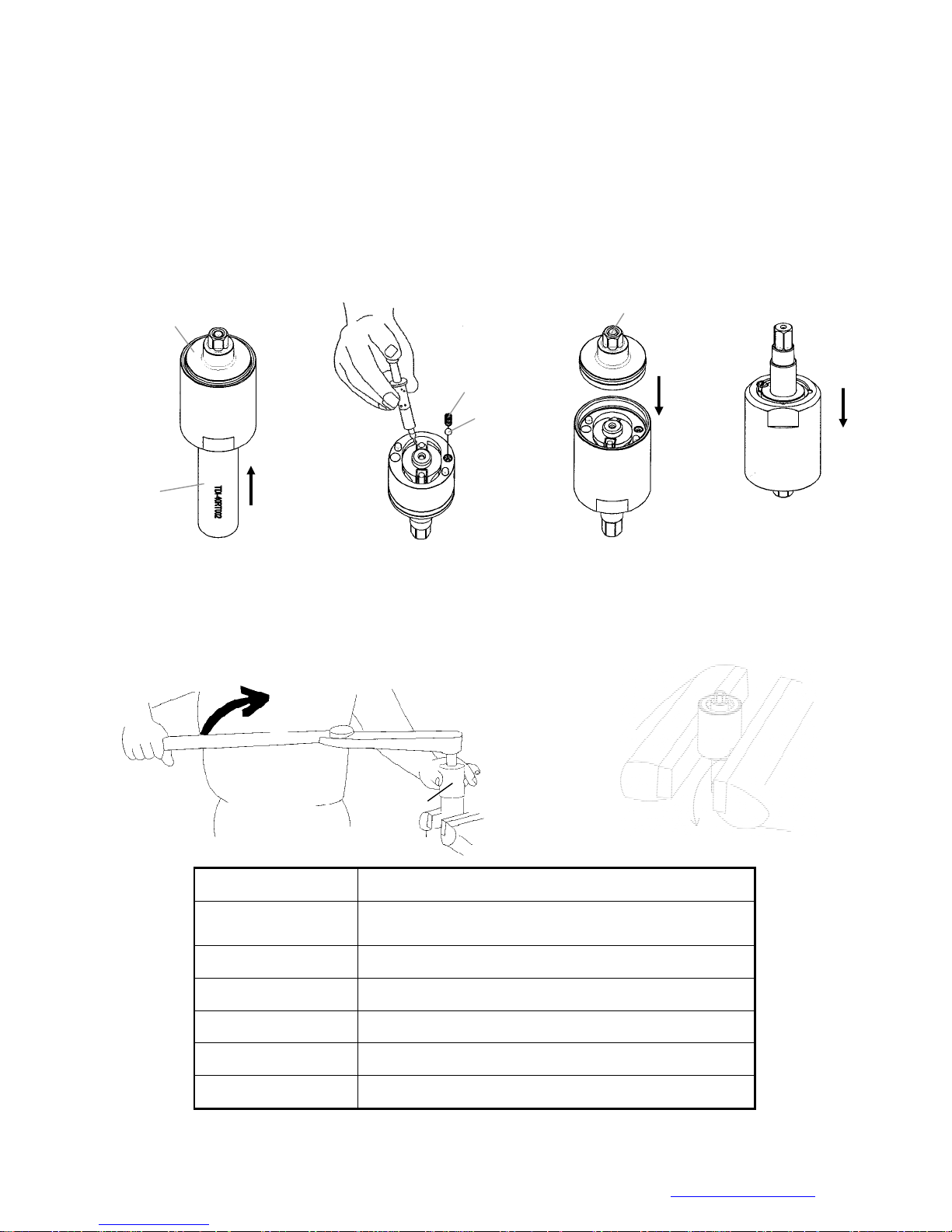
4.2 Use the appliance to push out the rear plate from the pulse cylinder seat. (See Chart 2) in
reference to the proper appliance selection. (Fig. 100)
Fill up the interior pulse cylinder with the pulse oil about 90% full by a syringe. Put the steel ball
4.3
and the valve spring into the hole on the pulse cylinder in order. (Fig. 101)
4.4 Install the rear plate taken from the step 2 on the pulse cylinder. Note the corresponding
positions
4.5 Turn the assembled unit up side down so the rear plate is at the bottom. Then press the pulse
cylinder seat all the way down to the fixed position. Make sure the corresponding positions are
matched exactly.
.
Rear Plate
Rear Plate
Valve Spring
Steel Ball
Appliance
Fig.100
Fig.101
Fig.102
Fig.103
4.6 Fix the pulse cylinder seat by a vise. Use an appliance and a torque wrench then turn clockwise to
tighten the lock nut of the pulse cylinder. (See Chart 14) in reference to the proper tightness.
(Note: Loctite needed when tightening the lock nut of the pulse cylinder)
Appliance No. Apply to
63-TDI-40RT001
63-TDI-70RT001 FLEXS-70P
63-TDI-90RT001 FLEXS-90P
63-TDI-100RT001 FLEXS-100P
63-TDI-130RT001 FLEXS-130P
63-TDI-150RT001 FLEXS-150P
Mountz Inc. 1080N 11th Street, San Jose CA 95112 Ph (408) 292-2214 Fax (408) 292-2733 www.mountztorque.com
Appliance
Fig. 104
Fixed by a vise
FLEXS-40P, FLEXS-50P, FLEXS-60P, FLEX-30PX ,
FLEXS-40PX , FLEXS-50PX , FLEXS-60PX
Chart 13
36
Page 37
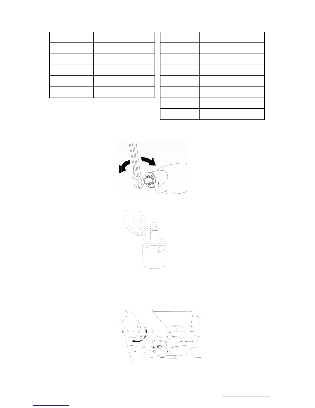
Model No. Tighten torque
FLEXS-40P 80 N.M
Model No. Tighten torque
FLEXS-100P 140 N.M
FLEXS-50P 80 N.M
FLEXS-60P 80 N.M
FLEXS-70P 100 N.M
FLEXS-90P 120 N.M
Chart 14
FLEXS-130P 150 N.M
FLEXS-150P 150 N.M
FLEXS-30PX 80 N.M
FLEXS-40PX 80 N.M
FLEXS-50PX 80 N.M
FLEXS-60PX 80 N.M
4.7 After completing the above steps, test to make sure the square drive of the anvil rotates freely.
5.0 Steps for Pulse Cylinder Oiling
5.1 Loosen the greasing screw, and inject the authorized oil by a syringe until it is full and overflow.
5.2 Take the unit and dip it in an oil tank, then rotate the anvil by a wrench to release air and the unit
would be full with oil completely.
Fig.105
Fig.106
Mountz Inc. 1080N 11th Street, San Jose CA 95112 Ph (408) 292-2214 Fax (408) 292-2733 www.mountztorque.com
Fig. 107
37
Page 38
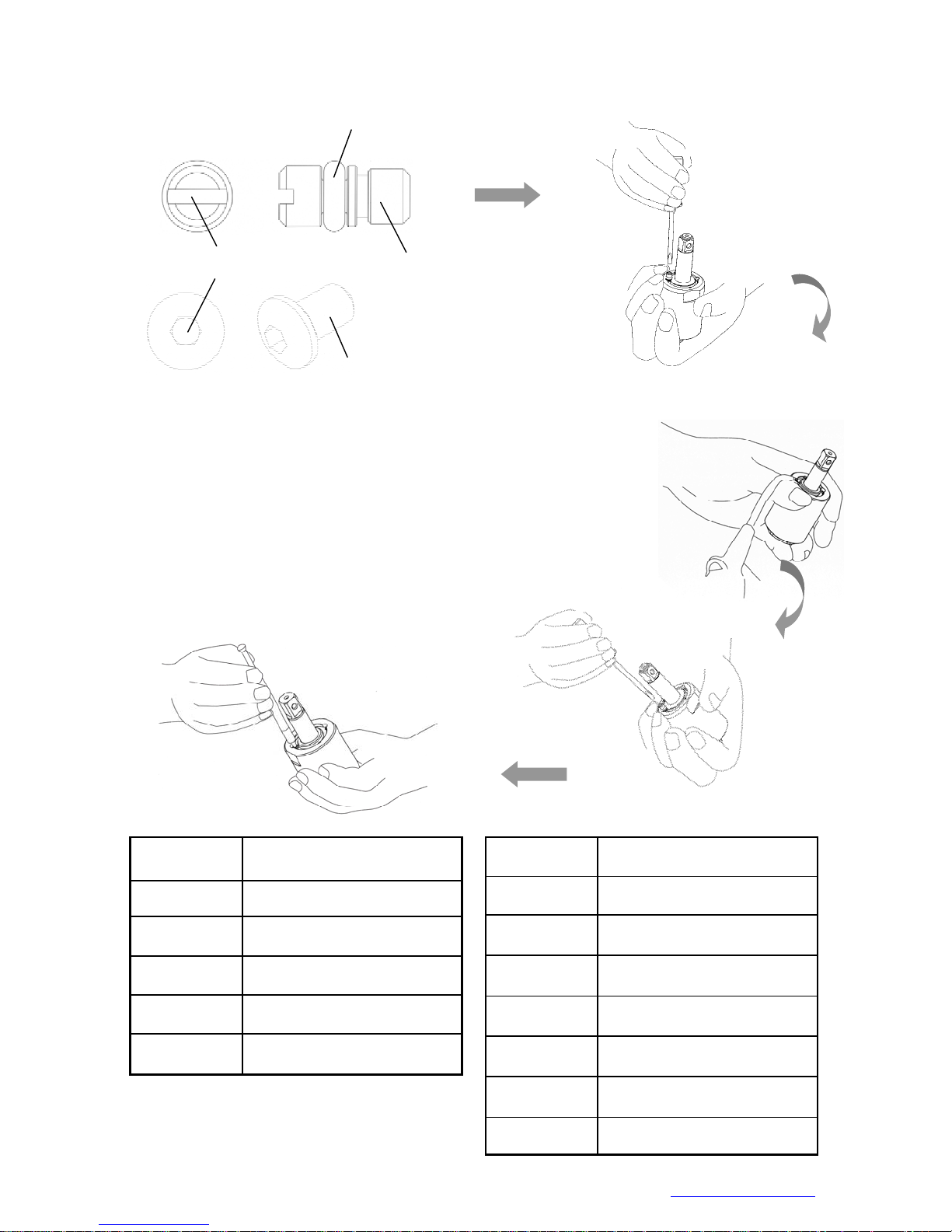
5.3 Use the screwdriver, the slotted or the hex one (for FLEXS-100P/ FLEXS-130P) to tighten the
greasing screw, (Fig. 10 8)
O-ring
Slotted
Hex
Greasing
Screw
Fig. 108
5.4 Use an air spray gun to blow off the oil on the cylinder seat, (Fig. 109)
5.5 Loosen the greasing screw again and use
a syringe to draw out a little amount of oil (see Chart 15) .
Finally, tighten the greasing screw back to
the pulse cylinder unit, (Fig. 110).
Greasing Screw
(for FLEXS-100P / FLEXS-130P)
Fig. 109
Model No. Amount of oil draw
FLEXS-40P 0.2 CC
FLEXS-50P 0.3 CC
FLEXS-60P 0.4 CC
FLEXS-70P 0.4 CC
FLEXS-90P 0.6 CC
Fig. 110
Model No. Amount of oil draw
FLEXS-100P 1.2 CC
FLEXS-130P 1.2 CC
FLEXS-150P 1.2 CC
FLEX-30PX 0.15 CC
FLEXS-40PX 0.2 CC
Mountz Inc. 1080N 11th Street, San Jose CA 95112 Ph (408) 292-2214 Fax (408) 292-2733 www.mountztorque.com
Chart 15
FLEXS-50PX 0.3 CC
FLEXS-60PX 0.4 CC
38
Page 39
r
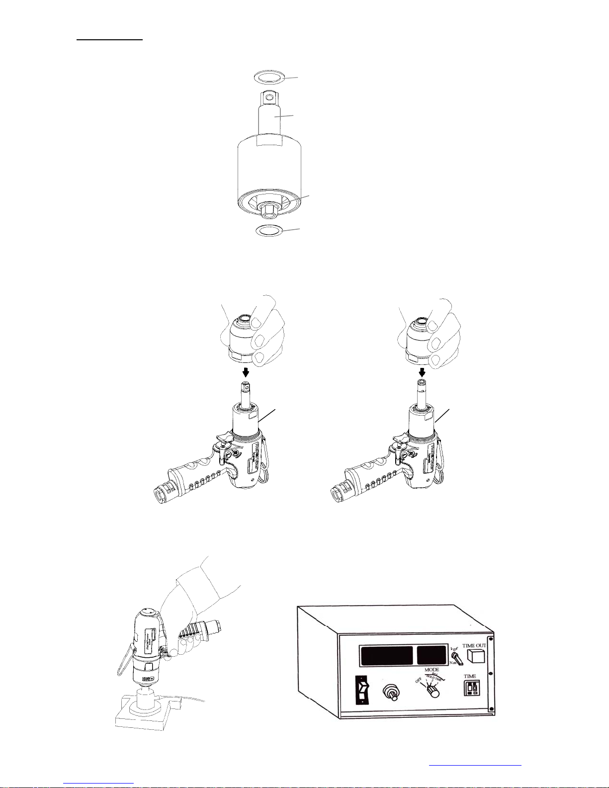
6.0 Torque Testing
6.1 Put the washer on the front end of the anvil, and then put another washer to the rear plate.
Washer
Anvil
Rear plate
Fig. 111
Washer
6.2 Tighten the clutch housing by hands.
Wrench series
Driver series
Fig.112
6.3 Test the forward torque by a digital torque tester and make sure the tool pulses smoothly.
Digital Torque Teste
Fig.113
Mountz Inc. 1080N 11th Street, San Jose CA 95112 Ph (408) 292-2214 Fax (408) 292-2733 www.mountztorque.com
39
Page 40
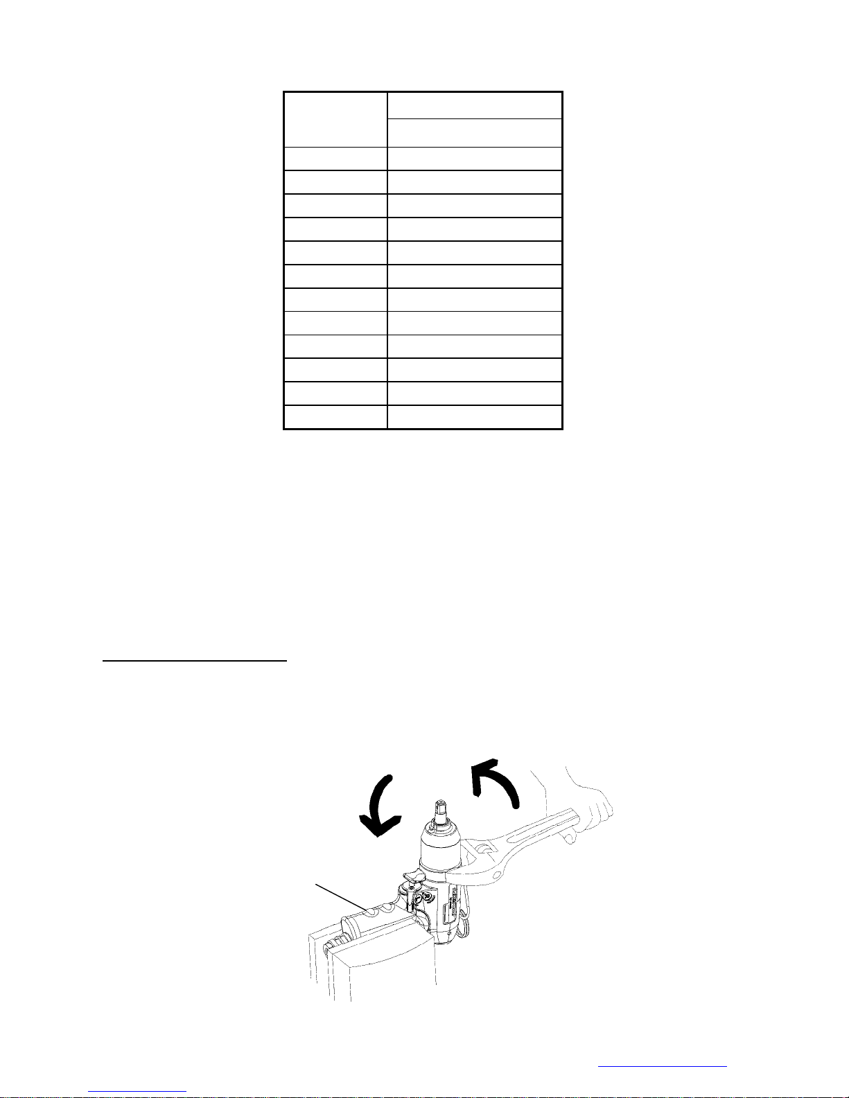
Chart 16
6.4 If the test result is NG (see Chart 16 in reference to the torque standard), MUST draw out or add a
Model No.
FLEXS-40P 15.5
FLEXS-50P 25
FLEXS-60P 35
FLEXS-70P 55
FLEXS-90P 90
FLEXS-100P 125
FLEXS-130P 145
FLEXS-150P 210
FLEXS-30PX 12.5
FLEXS-40PX 14
FLEXS-50PX 22
FLEXS-60PX 28
Air inlet pressure 85 PSI
N.M (at least)
little mount of oil and do the following steps:
6.4.1 Loosen the pulse unit housing by hands.
6.4.2 Loosen the greasing screw.
6.4.3 Draw out or add a little amount of oil.
6.4.4 Tighten the greasing screw back.
6.4.5 Tighten the pulse unit housing.
6.4.6 Test the torque again. If the test result is still NG, repeat the Steps 6.4.1 to 6.4.5 until
the proper torque is reached.
7.0 Pulse Unit Housing Assembly
Fix the housing by a vise. Turn the wrench in counter clockwise direction to tighten the pulse unit
housing.
Note: Handle rubber must
be covered by a piece of
cloth to avoid damage
Mountz Inc. 1080N 11th Street, San Jose CA 95112 Ph (408) 292-2214 Fax (408) 292-2733 www.mountztorque.com 40
Fig.114
Page 41
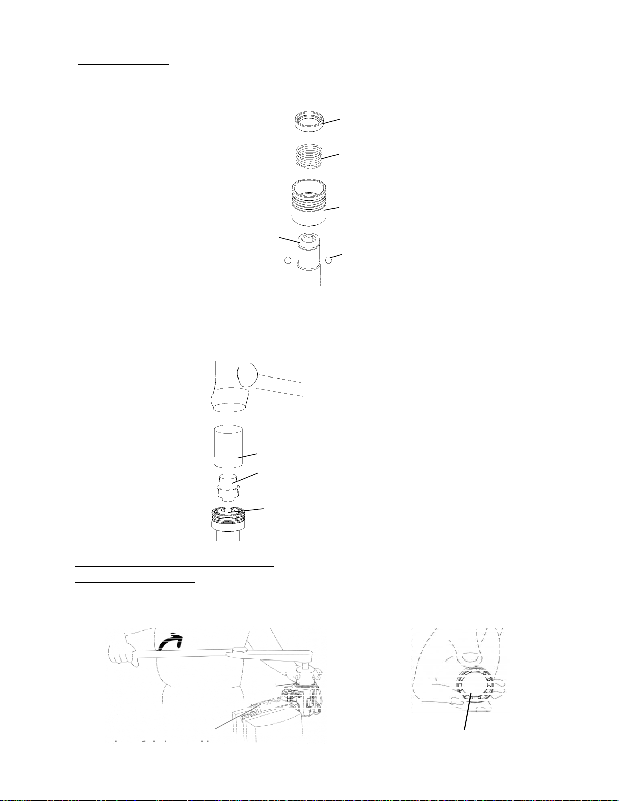
8.0 Anvil Unit Assembly
: (for the models: FLEXS-30PX ,FLEXS-40PX , FLEXS-50PX , and FLEXS-60PX)
(a) Place the steel ball, the quick change holder, the spring, and the hold spacer orderly as (Fig.
115 showed).
Hold Spacer
Spring
Anvil
Quick Change Holder
Steel Ball
Fig. 115
(b) Put the anvil collar on the Appliance # 63-TDI-40RT006, see Fig. 116.
(c) Place the 63-TDI-40RT006 on the hex-hole of the anvil, then put the Appliance # 63-TDI-40RT005 on the
63-TDI-40RT006 and tap it making sure the anvil collar sleeves into the anvil at proper positi on, see Fig.
116.
Appliance 63-TDI-40RT005
Appliance 63- TDI-40RT006
Anvil Collar
HOUSING AND MOTOR SET DISASSEMBLY:
1.0 Cylinder Unit Disassembly
:
1.1 Fix the tool by a vise. Place the appliance (see Chart 17) on the lock nut of the cylinder and turn
to loosen the lock nut out of cylinder in clockwise direction.
Note: Handle rubber
must be covered by a
Mountz Inc. 1080N 11th Street, San Jose CA 95112 Ph (408) 292-2214 Fax (408) 292-2733 www.mountztorque.com 41
Hex- hole of Anvil
Applian
Fig.117
Fig. 116
Lock nut of Cylinder
Page 42

Appliance No. Apply to
FLEXS-40P, FLEXS-50P, FLEXS-60P,
63-TDI-40RT004
63-TDI-90RT003 FLEXS-70P, FLEXS-90P
63-TDI-100RT003 FLEXS-100P
63-TDI-130RT003 FLEXS-130P
FLEXS-30PX ,FLEXS-40P X , FLEXS-50PX ,
FLEXS-60PX
1.2 Fix the housing in an opposite position. Use the appliance to loosen the lock nut of rear plate of cylinder in
counter clockwise direction.
63-TDI-150RT003 FLEXS-150P
Chart 17
Appliance
Note: Handle rubber must be
covered by a piece of cloth
to avoid damage
Appliance No. Apply to
63-TDI-40RT003
63-TDI-100RT002 FLEXS-70P, FLEXS-90P、FLEXS-100P
63-TDI-130RT002 FLEXS-130P
63-TDI-150RT002 FLEXS-150P
1.3 Loosen the screw by a wrench.
Mountz Inc. 1080N 11th Street, San Jose CA 95112 Ph (408) 292-2214 Fax (408) 292-2733 www.mountztorque.com 42
Fig. 118
FLEXS-40P, FLEXS-50P, FLEXS-60P, FLEXS-30PX ,
FLEXS-40PX , FLEXS-50PX , FLEXS-60PX
Chart 18
Fig.119
Page 43
g
V
g
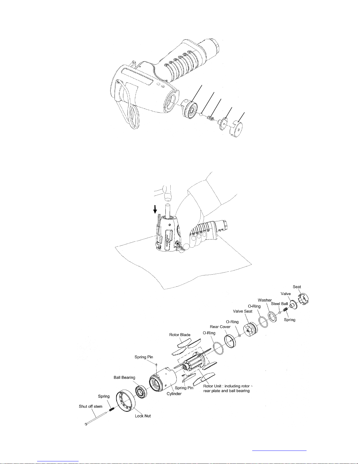
1.4 Detach the seat, the valve, the spring, the steel ball and the valve seat from the motor housing.
1.5 Take a piece of cloth and lay it on a Chart before disassembly. Hold the housing and tap slightly
with a plastic stick to push the cylinder unit out.
Fi
. 120
alve seat
Steel ball
sprin
valve
seat
1.6 Parts of Motor Set:
Fig.121
Mountz Inc. 1080N 11th Street, San Jose CA 95112 Ph (408) 292-2214 Fax (408) 292-2733 www.mountztorque.com
Fig. 122
43
Page 44
The rotor and the rear end plate must be press fit. The clearance of the two parts must be in between 0.01~
0.02 mm. It would not be easy to assemble the two parts by repair centers in general. Therefore, as there is a
need of repair on the parts of the rotor, the rear end plate, and the ball bearing, we strongly suggest
replacing a complete ROTOR UNIT, which is including the rotor, the rear plate, and the ball bearing. The rotor
unit would be full assembled and well-measured before delivery.
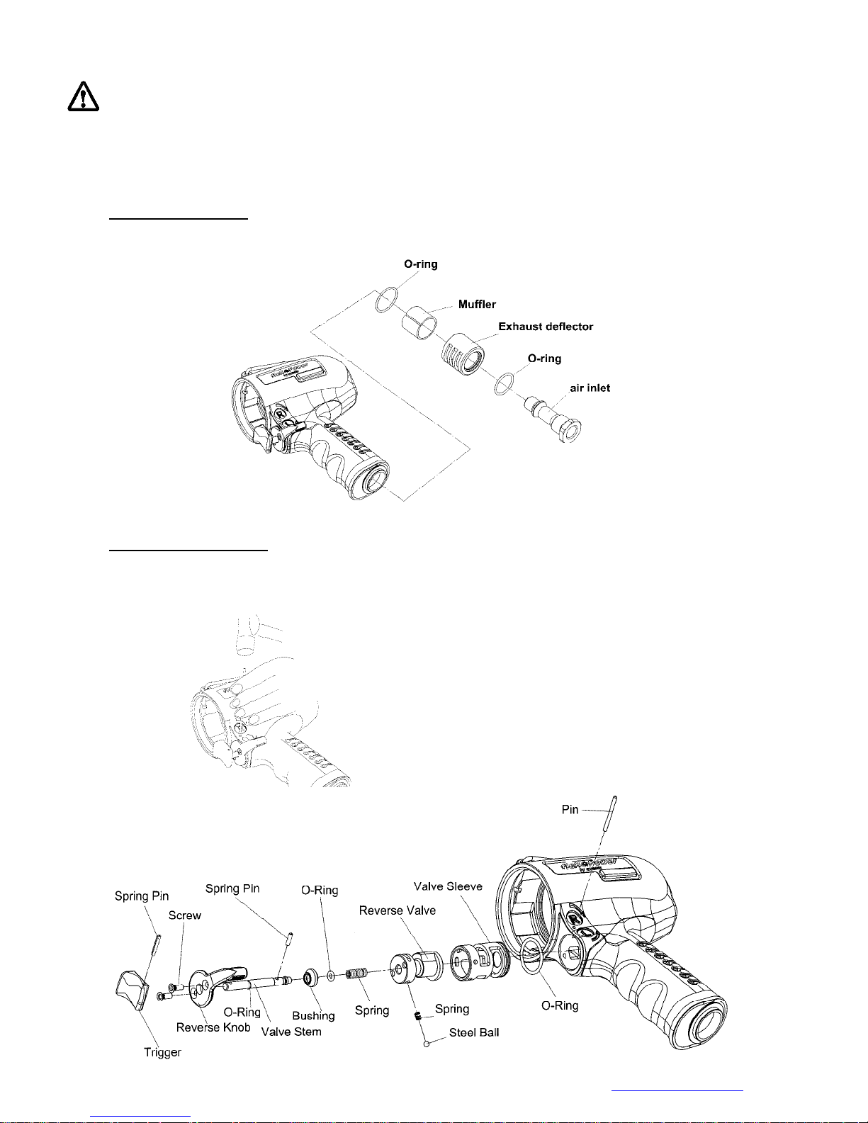
2.0 Air Inlet Disassembly:
Take the air inlet unit apart from the end of the housing. The parts of O-ring, Muffler, Exhaust deflector are
separated by each other.
Fig. 123
3.0 Trigger Set Disassembly:
Remove the pin to take apart the valve sleeve set. All the parts are disassembled as the below
drawing showed.
Fig. 124
Mountz Inc. 1080N 11th Street, San Jose CA 95112 Ph (408) 292-2214 Fax (408) 292-2733 www.mountztorque.com
44
Page 45
HOUSING AND MOTOR SET ASSEMBL Y:
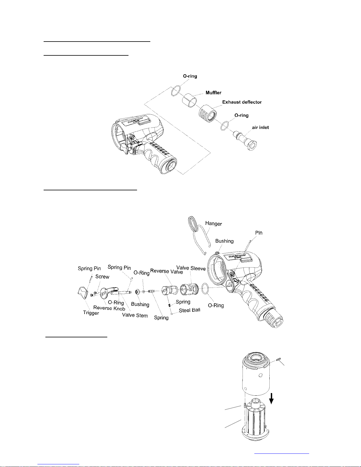
1.0 Housing and Air Inlet Assembly:
Install and tighten the parts of air inlet one by one and orderly. (NOTE: Apply the Loctite on the
threads of air inlet before assembly)
2.0 Housing and Trigger Set Assembly:
Install the parts of the trigger set orderly (see Fig. 126 drawing for reference). Then, Insert the pin to fix
all the parts. And, install the hanger to complete the assembly.
Fig. 125
Fig. 126
3.0 Cylinder Unit Assembly
3.1 Place the rotor blades into the rotor. Insert the spring pin A and B into the cylinder. Make sure the
pins aim at the pin holes when putting the cylinder down.
Spring pin B
Spring pin A
Rotor unit
Mountz Inc. 1080N 11th Street, San Jose CA 95112 Ph (408) 292-2214 Fax (408) 292-2733 www.mountztorque.com
45
Page 46
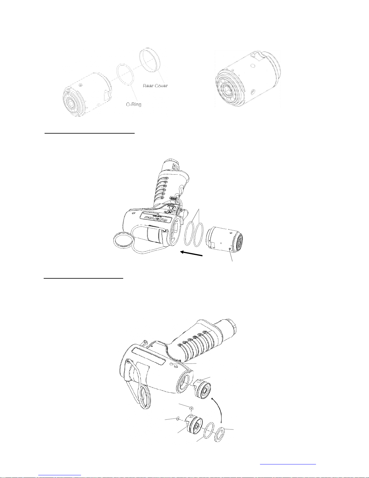
Fig.127
V
3.2 Install the O-ring and the rear cover to the rear plate. The motor set assembly is complete.
Fig. 128
4.0 Housing and Motor Set Assembly
Place two O-rings into the housing, then the motor set. Be sure the direction is correct when putting
the motor set in, i.e. the pin on the side cylinder must aim at the hole to fix position as Fig. 129 showed.
O-rings
5.0 Shut-Off Valve Unit Assembly
5.1 Place the three O-rings and the washer on the valve seat.
5.2 Place the assembled valve seat into the housing, making sure the hole on the side of valve seat
aims at the hole on the side of the motor housing and the two holes should be at the same
position in order to be fixed when the screw tighten in.
Fig. 129
Sprin g pin
Hole on the side of the motor housing
Hole on the side of Valve seat
O-ring
Fig. 130
Mountz Inc. 1080N 11th Street, San Jose CA 95112 Ph (408) 292-2214 Fax (408) 292-2733 www.mountztorque.com
O-ring
alve seat
washer
O-ring
46
Page 47
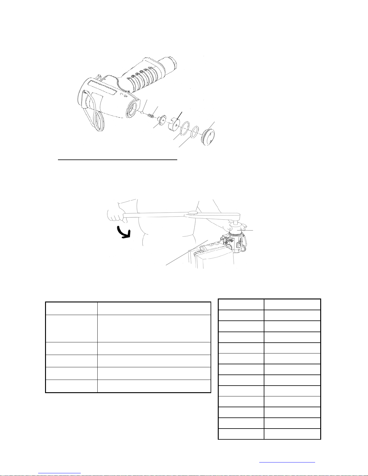
5.
3 Install the steel ball, the spring, the valve and the seat into the motor housing. Then, place the two
O-rings on the lock nut of the rear end plate and tighten it into the motor housing.
6.0 Housing and Lock Nut of Cylinder Assembly
Fix the tool by a vise. Place the lock nut of the cylinder nut and tighten by the appliance in
counter clockwise direction. Assembly is complete. See the Chart 19 and 20 in reference to
appliance use and tighten torque.
Steel ball
Spring
O-ring
O-ring
Seat
Fig.
Lock nut of Rear end plate
Appliance
Chart 19
Note: Handle rubber must
be covered by a piece of
cloth to avoid damage
Chart 20
Fig. 132
Appliance No. Apply to
FLEXS-40P, FLEXS-50P, FLEXS-60P,
63-TDI-40RT004
63-TDI-90RT003 FLEXS-70P, FLEXS-90P
63-TDI-100RT003 FLEXS-100P
63-TDI-130RT003 FLEXS-130P
63-TDI-150RT003 FLEXS-150P
FLEX-30PX ,FLEXS-40PX ,FLEXS-50PX ,
FLEXS-60PX
Model No. Tighten torque
FLEXS-40P 40 N.M
FLEXS-50P 40 N.M
FLEXS-60P 40 N.M
FLEXS-70P 60 N.M
FLEXS-90P 60 N.M
FLEXS-100P 60 N.M
FLEXS-130P 60 N.M
FLEXS-150P 60 N.M.
Mountz Inc. 1080N 11th Street, San Jose CA 95112 Ph (408) 292-2214 Fax (408) 292-2733 www.mountztorque.com
FLEX-30PX 40 N.M
FLEXS-40PX 40 N.M
FLEXS-50PX 40 N.M
FLEXS-60PX 40 N.M
47
Page 48
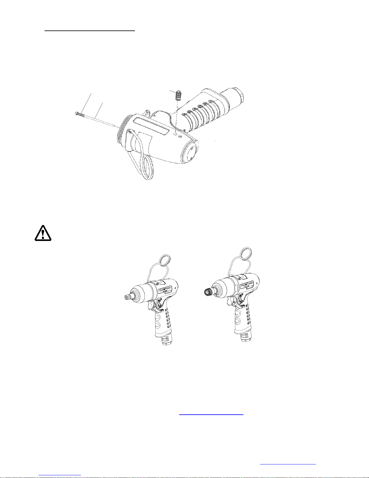
7.0 Tighten the screw on the housing
Before tightening the screw, make sure the hole of the housing should be at the same position where the
hole of the seat at in order to assure the screw can tighten into the housing and the seat properly. Finally,
insert the shut off stem with the spring sleeved into the center of the rotor. Assembly is complete.
Note: Loctite needed when tighten the screw.
Spring of the pin
Shut off stem
Screw
Fig. 133
After all the assembly is complete, test to make sure the anvil rotates freely, then connect the air hose
and test the torque.
For more specific information or assistance for your FLEX POWER TOOLS , please contact your local Sales
Engineer or contact any of our Serivce Centers
Fig.134
Mountz Inc. 1080N 11th Street, San Jose CA 95112 Ph (408) 292-2214 Fax (408) 292-2733 www.mountztorque.com
48
Page 49

Trouble Shooting
Trouble Cause Solution
No Shut-off occurs
Premature S hut-o ff or
uncompleted rundown
Overfill oil or missing oil in the pulse
unit
Draw or add the amount of oil
needed.
Push rod or spring worn out Replace the push rod and spring.
Low Air pressure or incorrect hose size
and air fittings
Adjust desired air pressure when the
tool is running freely.
Select the correct hose size and the air
fittings, according to the tool model.
Missing Cap (rear plate) Replace the parts.
Oil and/or O-rings broke down Change the oil O-rings if worn out or
bad condition.
Excess of oil in the pulse unit Draw the excess of oil from the pulse
unit.
Torque setting Adjust the target torque as
recommended.
Extensions or extra length sockets Use sleeve drive sockets for
extension or different length need.
Join characteristic Use a bigger model or a non-shut off
tool, if the joint is soft or there is a
prevailing torque.
Inconsistence torque output
or low T orque
Low RPM’s
Low air pressure or fluctuates Adjust desired air pressure when the
tool is running freely.
Lack of CFM on the air motor Check the air compressor capacity.
Dry blades of the air motor Lubricate the air motor and
recommended to add two or three
drops per week.
Oil and/or O-rings broke down Change the oil O-rings if are worn out
or bad conditions
Low air pressure or fluctuates Adjust desired air pressure when the
tool is running freely.
Dry blades of the air motor Lubricate the air motor and
recommended to add two or three
drops per week.
49
Page 50

Service Centers
Headquater & Western Service Center
1080N 11th Street
San Jose, CA 95112
P. 408.292.2214
F. 408.292.2733
Contact: [email protected]
Eastern Distribution & Service Center
19051 Underwood Rd.
Foley , AL 36535
P. 251.943.4125
F. 251.943.4979
Contact: [email protected]
Mexico Service Center
Mountz Mexico S.A. de C.V.
Av. Cristobal Colon # 15434
Col. Paseos de Chihuahua
Chihuahua, Chih. 31125
P. 614.481.0023
F. 614.481.0053
Contact: [email protected]
50
 Loading...