

Page 1
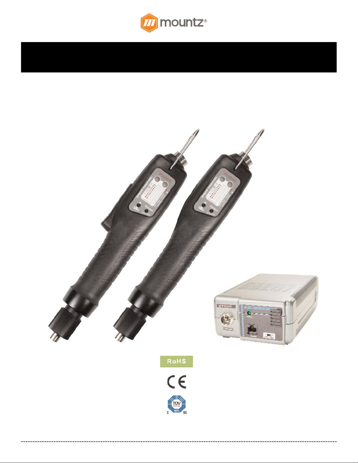
BF-Series (BF060, BF080 & BF120 models)
Operation Instructions
Corporate Headquarters: 1080 North 11th Street, San Jose, CA95112 Phone: (408) 292-2214 Fax: (408) 292-2733
www.mountztorque.com
Page 1
Rev 2.2 (4/13/17)
for V3 Models Only
Page 2
BF-Series (BF060, BF080 & BF120 models) Operation Instructions
Introduction
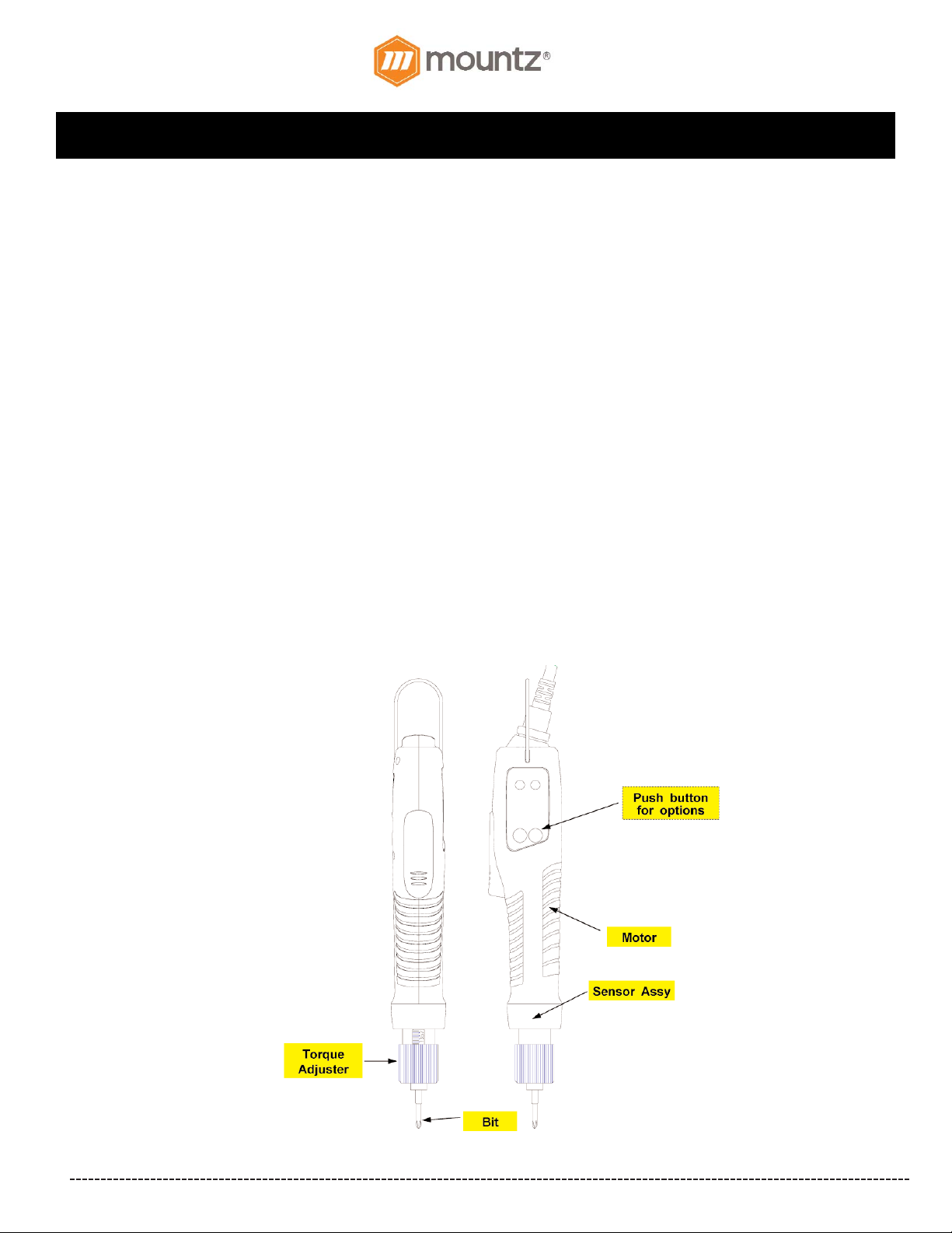
- Various models that range from 0.17 - 10.4 lbf.in
- High performance Swiss Maxon brushless motor design provides durability and reduces the standard maintenance costs for
electric screwdrivers.
- Designed for high production environments. Minimal heat build-up even when tool is operated continuously.
- Over Heat Protection (OHP) and Over Current Protection (OCP) protect driver from damage or malfunction. Features a LED
display that signals the tool status for the operator to view.
- Can be connected with the Scout Screw Counter.
- External torque adjustment scale.
- Requires transformer (power supply).
- All models are ESD designed and prevent the occurrence of electrostatic discharge, which improves production yields,
manufacturing costs, product quality, product reliability, reputation and profitability.
Four style of brushless screwdriver models:
- Standard models: Adjustable RPM setting on the tool. A selectable Soft Start mode from 0.2-0.6 seconds. (Lever Start &
Push-to-Start)
- Soft Stop models: Precision "Soft-Stop" clutch prevents shock to sensitive assemblies like disk drives, plastics, electronics, etc.
Adjustable RPM setting on the tool. Aselectable Soft Start mode from 0.2-0.6 seconds. (Lever Start)
- Angle Control & Auto Reverse models: Set the start, stop and operating direction of the tool. Adjustable RPM setting on the \
tool.(Lever Start)
- Plus models: Features a selectable Double Hit Mode for soft joint applications and a selectable Soft Start mode (from 0.2-0.6
seconds). This option is available for Standard & Soft Stop screwdrivers (Lever Start & Push-to-Start)
Corporate Headquarters: 1080 North 11th Street, San Jose, CA95112 Phone: (408) 292-2214 Fax: (408) 292-2733
www.mountztorque.com
Page 2
Page 3
BF-Series (BF060, BF080 & BF120 models) Operation Instructions
Corporate Headquarters: 1080 North 11th Street, San Jose, CA95112 Phone: (408) 292-2214 Fax: (408) 292-2733
www.mountztorque.com
Page 3
General Operation for BF-Series models
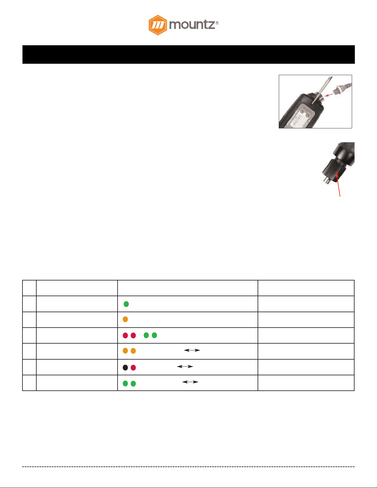
1. Attach power tool cable to the BF-Series screwdriver and the transformer. Make sure notch at the
cable end aligns with the notch on the driver connector. Tighten knurled ground ring.
2. Plug in power cord to the back of the transformer and power outlet. Flip power switch to
“ON” position located on the back of transformer.
3. Select a bit. Slide the bit collar forward. Insert the bit and release the collar. To avoid damaging
fasteners, make sure the proper bit is suitable for the head of the fastener.
4. The torque limit is determined by the tension of the coil spring housed in the tool. The tighter the coil
spring is wound the higher the torque limit is raised. See Torque Charts on pages 14 & 15 to determine the
appropriate torque adjustment setting.
5. Rotate the torque adjustment nut to set the torque limit. Turn clockwise to increase torque and counter
clockwise to decrease torque. The scale adjacent to the Torque Adjustment Nut is a reference guide. The
torque output from the driver can change depending on various fastening factors like friction, type of
joint, and the type material being used like a washer. Verify torque setting with a torque testing system.
7. Turn driver on and check for proper rotation. FOR-clockwise, REV-counterclockwise.
8. To apply torque, squeeze the lever (Push-to-Start models - place light downward pressure on the nose
of the driver). The driver will automatically stop when the preset torque has been reached.
9. To remove the screw, turn the FOR/REV switch to REV position.
Information by Color LED for BF brushless screwdriver
The LED display signals the tool status for the operator. It’s located on the side of the tool. Below is the LED display indicator for reference.
torque
adjustment nut
No. Description Display Reset
1 START (Before torque up) Green (left one) Synchronized with start START OFF
2 START (After torque up) Orange (left one) Synchronized with start START OFF
3 Over voltage input (over 32V) R/G change two colors in 0.5s
Automatically resets when it’s below
DC32V.
4 Over load (over 1.5A/0.5s) Orange color ON OFF in 0.5s Automatically resets after 5 seconds.
5 Over temperature (over 80ºC) Red color ON OFF in 0.5s
Automatically resets when it’s below
80ºC.
6 Driver Lock (Remote) Green color ON OFF in 0.5s By remote
Page 4
BF-Series (BF060, BF080 & BF120 models) Operation Instructions
Corporate Headquarters: 1080 North 11th Street, San Jose, CA95112 Phone: (408) 292-2214 Fax: (408) 292-2733
www.mountztorque.com
Page 4
BF-Series Standard Models & Soft Stop Models
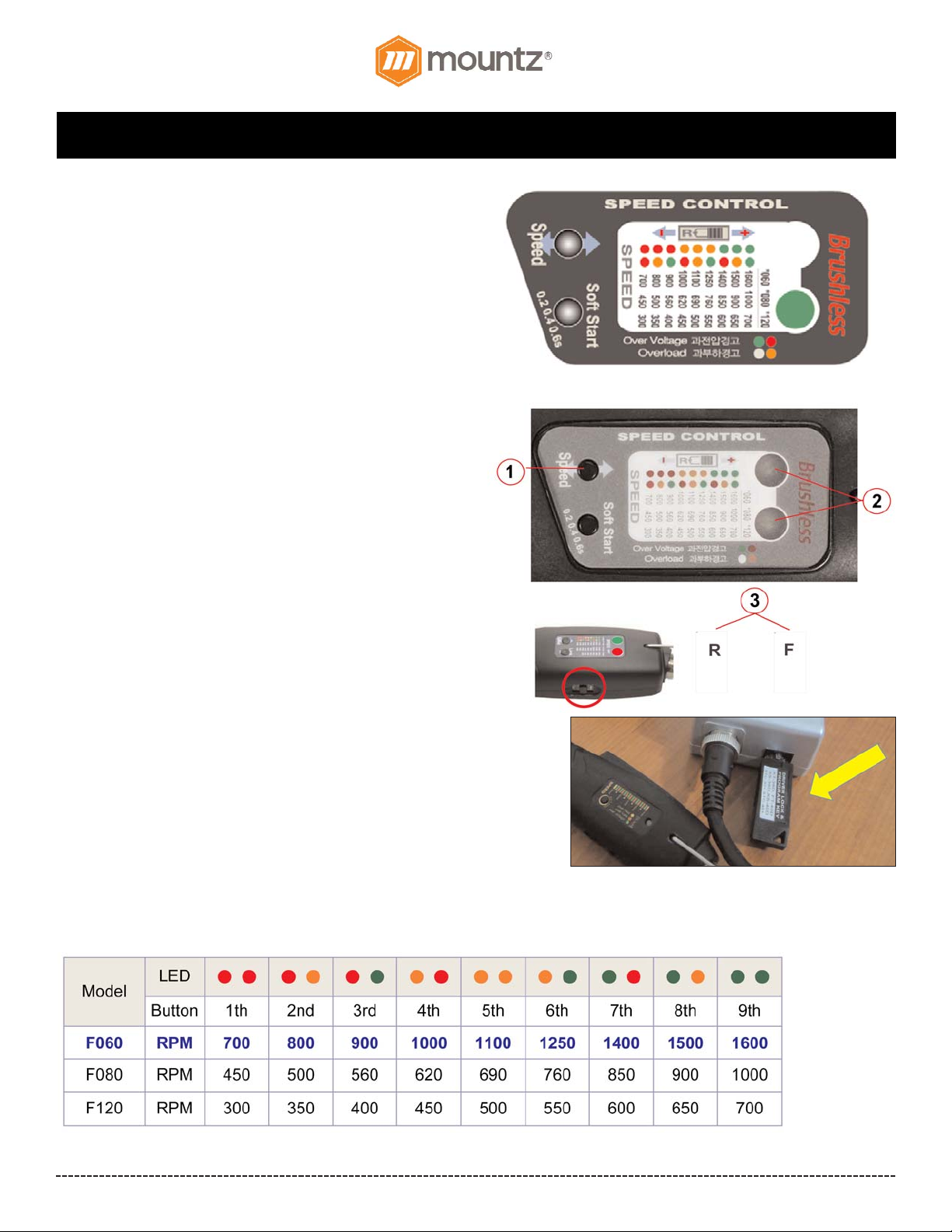
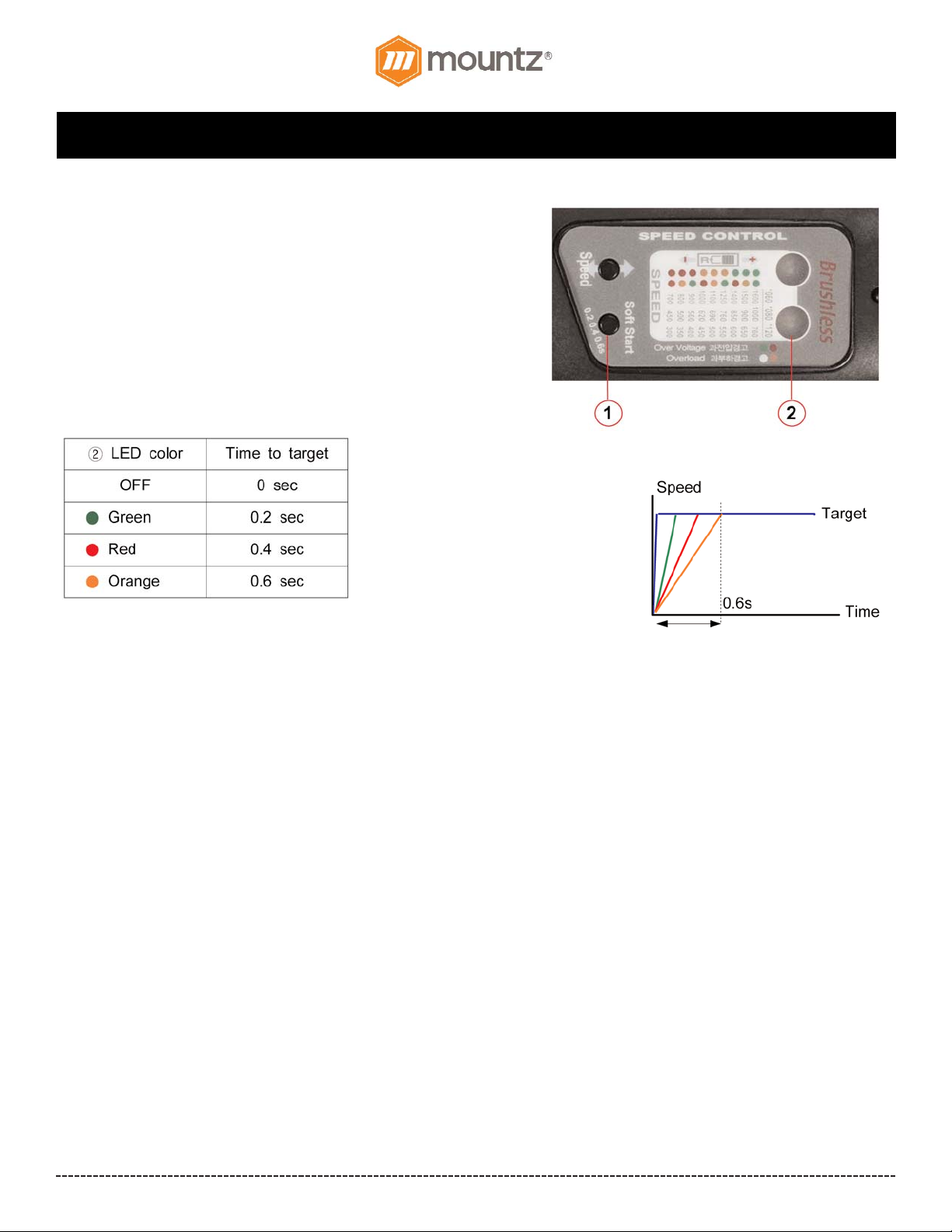
These models feature an adjustable RPM setting on the tool. The
RPM settings can be adjusted to the preset increments as shown
label (see image on the right).
These models also feature a selectable Soft Start mode (from 0.2,
0.4 & 0.6 seconds).
How to Adjust Speed Setting
1. Press and hold the Speed button for 2 seconds.
2. Two LEDs will display colors that show the current speed
selection of the brushless screwdriver.
3. Position the F/R slide switch in R or F to increase (+) or decrease
(-) RPM setting of the tool Slide switch to "R" position to increase
speed. Slide switch to "F" to decrease speed. Then press the
Speed button until the target speed is selected. The two LEDs
will display colors that show the current speed selection (see
table below for reference) Note! The RPM settings can only be
adjusted to the preset increments as shown on the label
(see chart below).
4. By starting the screwdriver, the selected speed is saved
automatically.
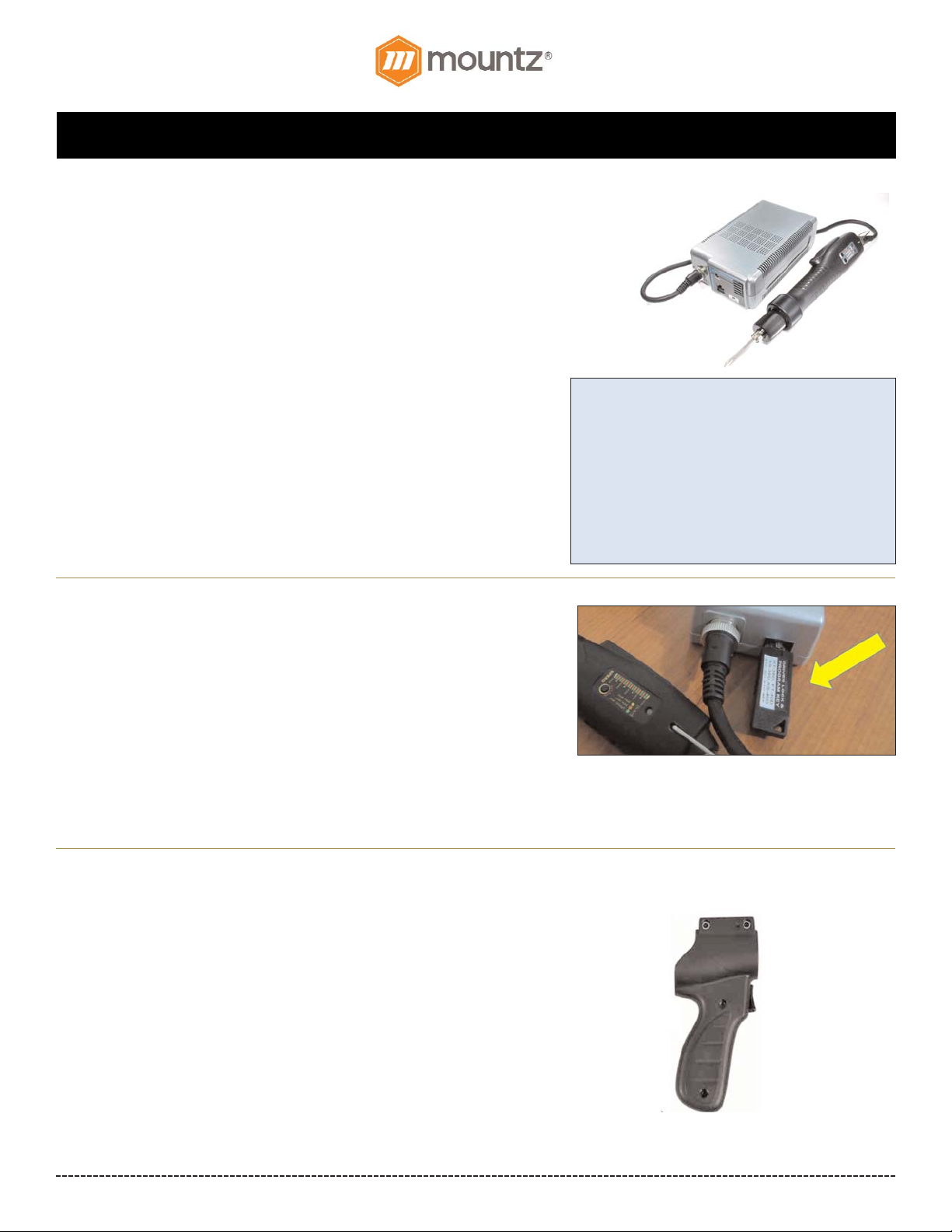
Program Lock Key
The Program Lock Key protects from incidental or operator tampering of the
programmable settings on the side of select BF-Series models* (V3 models
only). To adjust the settings the Program Lock Key must be is plugged into
the STC40 & FT-30D Mini Transformer.
Note! The program Key cannot be used with BF-Series Standard Plus
Models, Soft Stop Plus Models & Angle & Auto Reverse Models.
Speed Selection
To adjust the settings the Program Lock Key
must be is plugged into the STC40 & FT-30D
Mini Transformer.
Page 5
BF-Series (BF060, BF080 & BF120 models) Operation Instructions
Corporate Headquarters: 1080 North 11th Street, San Jose, CA95112 Phone: (408) 292-2214 Fax: (408) 292-2733
www.mountztorque.com
Page 4
BF-Series Standard Models & Soft Stop Models (continued)
How to Adjust Soft Start Setting
There are 3 different time settings for the Soft Start mode which are (0.2,
0.4 & 0.6 seconds). The default setting is OFF.
1. Press and hold the Soft Start button for 2 seconds.
2. Two LEDs will display colors that show the current soft start
selection of the brushless screwdriver.
3. Press Soft Start button until the target time is selected.
4. By starting the screwdriver, the selected soft start setting is saved
automatically.
The Soft Start button is “wrap around” button meaning you can toggle through the settings continuously by pressing the button
(OFF - 0.2s-0.4s-0.6s).
Page 6
BF-Series (BF060, BF080 & BF120 models) Operation Instructions
Corporate Headquarters: 1080 North 11th Street, San Jose, CA95112 Phone: (408) 292-2214 Fax: (408) 292-2733
www.mountztorque.com
Page 6
BF-Series Standard Plus Models & Soft Stop Plus Models
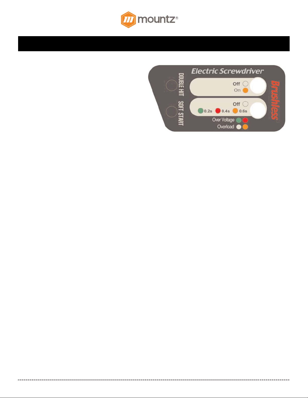
The “Plus” models feature a selectable Double Hit Mode
for soft joint applications and a selectable Soft Start mode
(from 0.2, 0.4 & 0.6 seconds). This option is only available
with Standard & Soft Stop “Plus” models.
Double Hit Mode
The Double Hit mode is for very soft joint applications. When
an electric screwdriver runs down a fastener and the tool
clutches off once the preset torque is achieved there can be
some joint relaxation that can occur. The Double Hit mode
has the electric screwdriver perform a second hit to stabilize
the torque for joint relaxation.
Joint relaxation is caused by the surface of part(s) embedding or by "soft parts" such as gaskets, plastics or spongy material, which
collapses under the clamping force created in a torque condition. For Hard Joint applications there is no need to use the Double Hit
mode.
The clutch of the electric driver works twice at the set torque under the "Double Hit" mode. The Double Hit will increase the
repeatability accuracy at the target torque by double checking.
Operating the Double Hit Feature with “Plus” models
The default setting is OFF.
1. Press the Double Hit button for 2 seconds to turn ON Double Hit. (ON Status is indicated with LED - Orange). Note - When the
motor is operating LED will be Green.
Soft Start Mode
There are 3 different time settings for the Soft Start mode which are (0.2, 0.4 & 0.6 seconds). The default setting is OFF.
1. Press the Soft Start button for 2 seconds to turn on Soft Start.
- Soft Start is ON and set for 0.2s (LED - Orange)
- Soft Start is ON and set for 0.4s (LED - Orange blinks 1 time)
- Soft Start is ON and set for 0.6s (LED - Orange blinks 2 time)
The Soft Start button is “wrap around” button meaning you can toggle through the settings continuously by pressing the button
(OFF - 0.2s-0.4s-0.6s).
Page 7
BF-Series (BF060, BF080 & BF120 models) Operation Instructions
Corporate Headquarters: 1080 North 11th Street, San Jose, CA95112 Phone: (408) 292-2214 Fax: (408) 292-2733
www.mountztorque.com
Page 7
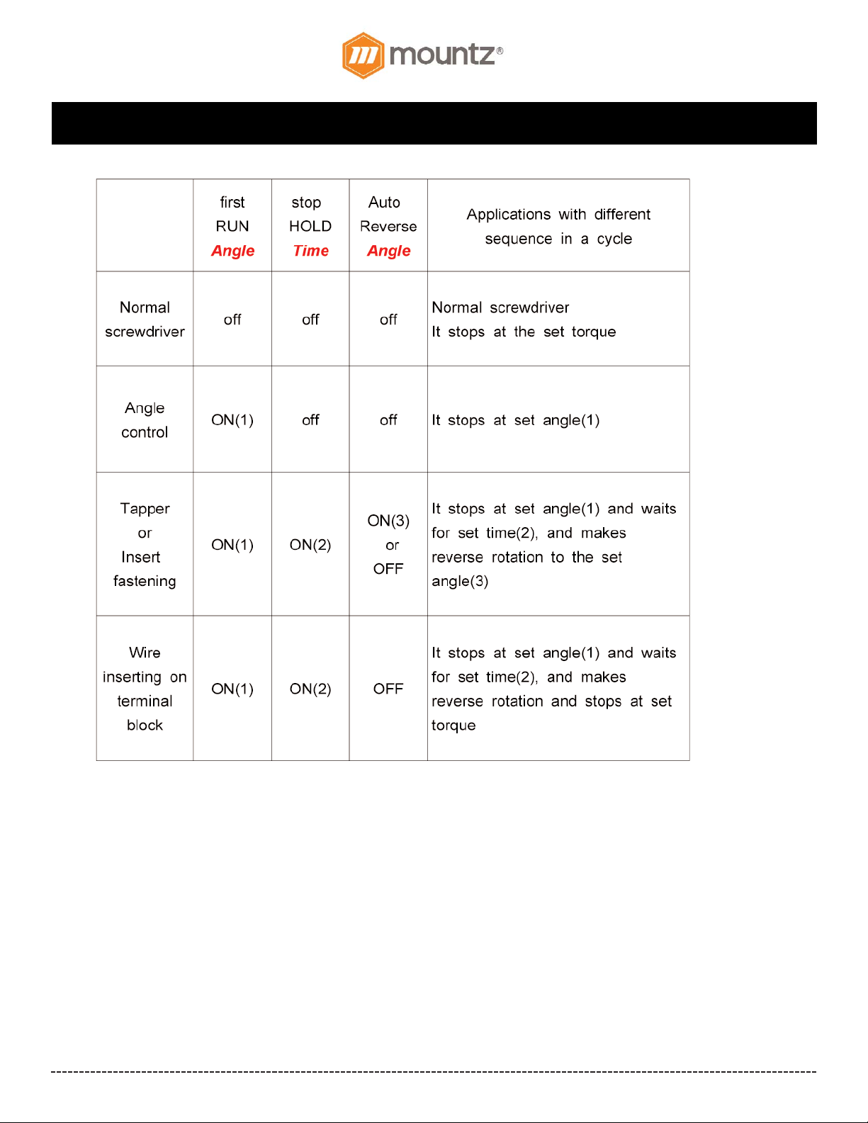
BF-Series Angle Control & Auto Reverse models
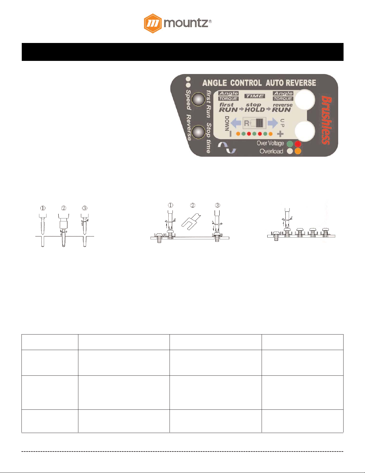
Set the start and stop point by angle control within a range
of 0.25 - 15 turns. Also set the “Stop Holding Time” within a
range of 0.1 to 6 seconds. Adjustable RPM is at increments
of 50 RPM units.
Ideal for installation of heli-coil wound inserts, light tapping
or gauging applications.
Example 1.
Start from selected rotation by the lever and
immediately change rotation to reverse at
the set torque or releasing the lever. Useful
for Tapping and Heli-coil fastening.
Example 2.
Start from Reverse rotation by the lever for
set time (A) and stop for a set time (B),
then auto run for Forward fastening by set
torque.
1. Start forward rotation.
2. Stop at the target torque or set time.
3. Auto reverse rotation and stop at
releasing the lever or set time.
1. Start from reverse rotation.
2. Stop at the set time and wait for set
time.
3. Auto forward rotation and stop at
the target torque.
Example 3.
Fasten or unfasten the set turns
by timer.
Start, Stop and Direction.
There are three sequences for this process: Start, Stop and Direction. With one pull of the lever on the electric screwdriver all 3
sequences occur within programmed cycle.
Step 1 2 3
Sequence First Run Stop & Hold Reverse Run
Selecting Rotating Clockwise or Reverse
Direction Counterclockclockwise
by F/R Switch
Activating Run and stop for set Stop and hold for set time Rotate reverse until
time (angle) or stop at the target releasing the lever or stop
torque at the preset torque or angle
Time (Angle) Setting 0-15 turns / 24 steps 0-6 sec / 14 steps 0-15 turns / 24 steps
Page 8
BF-Series (BF060, BF080 & BF120 models) Operation Instructions
Corporate Headquarters: 1080 North 11th Street, San Jose, CA95112 Phone: (408) 292-2214 Fax: (408) 292-2733
www.mountztorque.com
Page 8
Operating BF-Series Angle Control & Auto Reverse
models
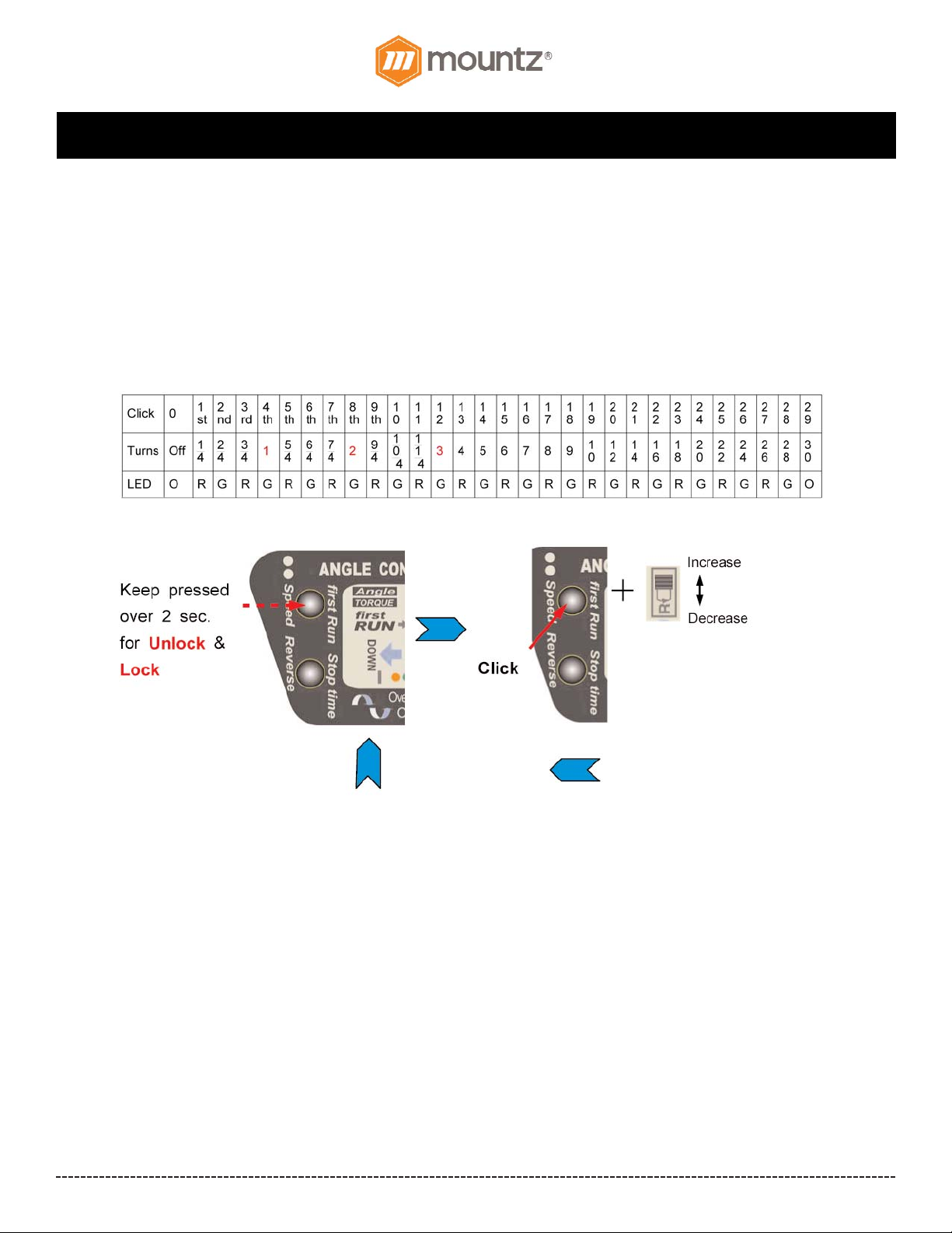
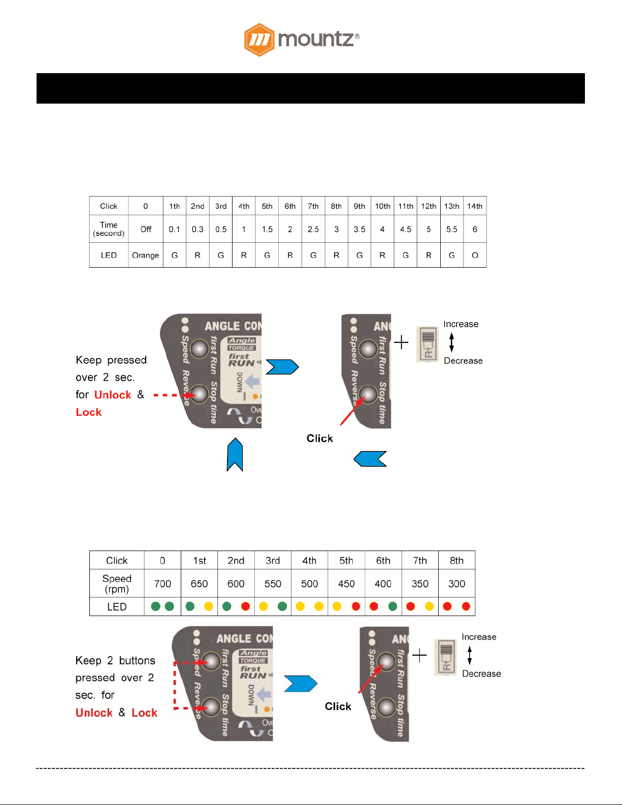
Angle Setting for the first RUN
1. Keep the first Run button pressed for over 2 seconds for angle setting. Then press first Run button one by one for the desired
rotating angle.
2. Select the R position of F/R switch for increasing set angle or F position for decreasing set angle.
3. Keep the first Run button pressed over 2 sec. for Lock & operating mode.
Page 9
BF-Series (BF060, BF080 & BF120 models) Operation Instructions
Corporate Headquarters: 1080 North 11th Street, San Jose, CA95112 Phone: (408) 292-2214 Fax: (408) 292-2733
www.mountztorque.com
Page 9
Time Setting for STOP & HOLD
1. Keep the stop time button pressed over 2 seconds. Then click the stop time button one by one for desired stop holding time.
2. Select the R position of F/R switch for increasing set time or F position for decreasing set time.
3. Keep the stop time button pressed over 2 sec. for Lock & operating mode.
Rotating speed setting
1. Keep the both first Run & stop time buttons pressed over 2 seconds for unlock. Then click one by one for the desired rotating
speed.
2. Select the R position of F/R switch for increasing speed or F position for decreasing speed.
3. Keep the first Run button pressed over 2 sec. for Lock & operating mode.
Page 10
BF-Series (BF060, BF080 & BF120 models) Operation Instructions
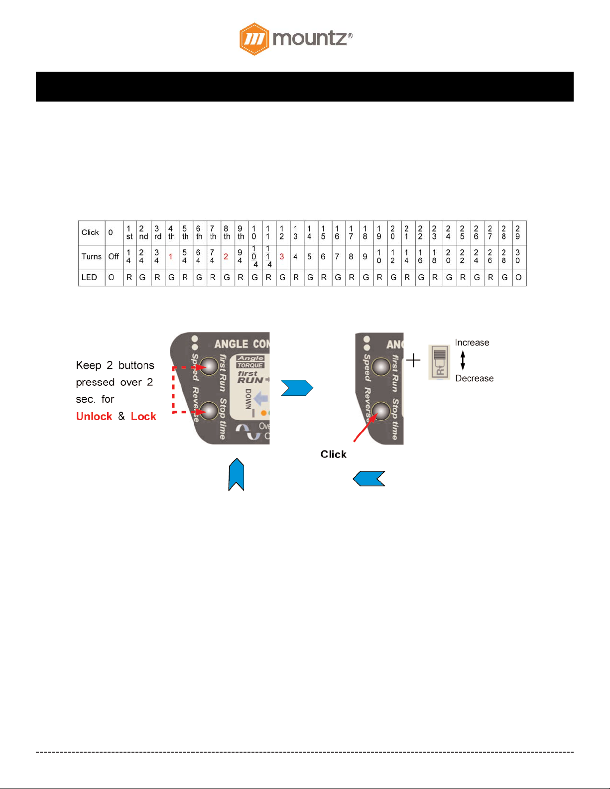
Angle Setting for the reverse RUN
1. Keep the both first Run & stop time buttons pressed over 2 seconds for unlock. Then click stop time button one by one for the
desired angle
2. Select the R position of F/R switch for increasing set angle or F position for decreasing set angle
3. Keep the stop time button pressed over 2 sec. for Lock & operating mode.
Corporate Headquarters: 1080 North 11th Street, San Jose, CA95112 Phone: (408) 292-2214 Fax: (408) 292-2733
www.mountztorque.com
Page 10
Page 11
BF-Series (BF060, BF080 & BF120 models) Operation Instructions
Corporate Headquarters: 1080 North 11th Street, San Jose, CA95112 Phone: (408) 292-2214 Fax: (408) 292-2733
www.mountztorque.com
Page 11
Page 12
BF-Series (BF060, BF080 & BF120 models) Operation Instructions
Corporate Headquarters: 1080 North 11th Street, San Jose, CA95112 Phone: (408) 292-2214 Fax: (408) 292-2733
www.mountztorque.com
Page 12
Features
- Over Heat Protection (OHP) and Over Current Protection (OCP) protect
driver from damage or malfunction.
- Temperature Detection powers down the unit and resets automatically when
unit restores to acceptable levels.
- Switchable 110V & 230V input voltage. Unit will reset itself if motor/current
overload is too high.
- Start & Stop Signal Output (for PLC).
- Screwdriver Lock Signal Input (for PLC).
- Unit can be connected to the Scout (Screw Counter).
Model: STC40
Item # 145754
Specifications:
Rated Output: 2.6A 105W
Max. Output: 10A
Output VDC: 30/40V
Input VAC: 110/230V
Size inches (W x D x H): 4 3/8” x 7 1/2” x 2 3/8”
Weight: 1.8 lbs.
Operates with: BF-Series and NF-Series
STC40 transformer is power supply designed for operating the BF-Series & NFSeries brushless electric screwdrivers. Only use this transformer when operating
any BF-Series & NF-Series models.
Power Supply (Transformer)
Program Lock Key - Item # 145774
The Program Lock Key protects from incidental or operator tampering of the
programmable settings on the side of select BF-Series models* (V3 models only).
To adjust the settings the Program Lock Key must be is plugged into the STC40 &
FT-30D Mini Transformer.
* Note! The program key is required for the BF-Series Mini models, Standard
Models and Soft Stop Models. RPM & Soft Start Settings cannot be adjusted
without it.
The program Key cannot be used with BF-Series Standard Plus Models, Soft Stop Plus Models & Angle & Auto Reverse
Models.
Accessories
Pistol Grip Attachment
The Pistol Grip attachment is an accessory item that converts the BF-Series inline electric screwdrivers into pistol grip style tools.
For: BF060, BF080 & BF120 models
Item # 145788
Page 13
BF-Series (BF060, BF080 & BF120 models) Operation Instructions
Corporate Headquarters: 1080 North 11th Street, San Jose, CA95112 Phone: (408) 292-2214 Fax: (408) 292-2733
www.mountztorque.com
Page 13
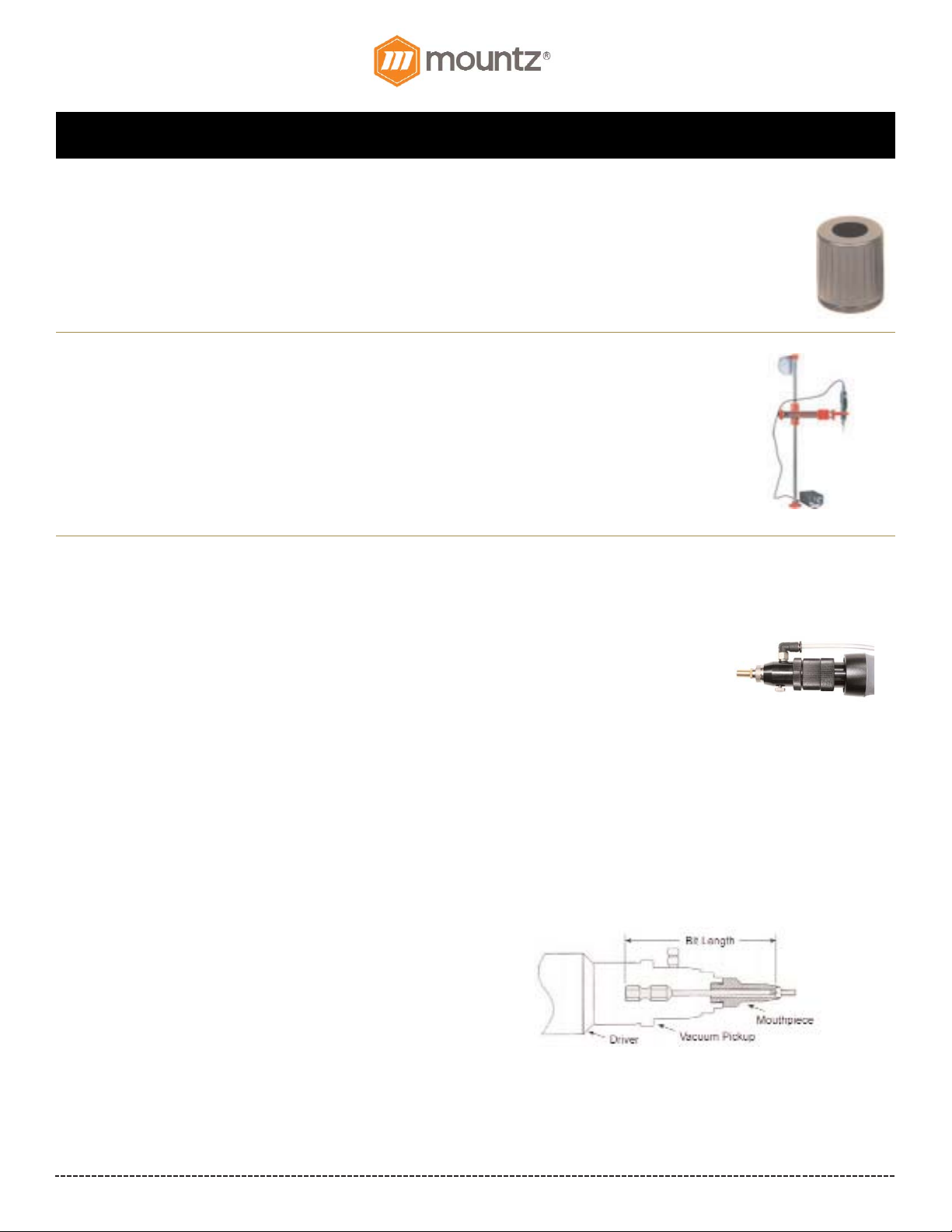
Vacuum Adapter Kit
Vacuum adapter kits can be mounted on an electric screwdriver. The screwdriver is fitted with a suction head that holds the screw on
the bit, enabling the operator to pick it up with the tool itself. This is an effective, time saving device that works with most fasteners.
Accepts different size screws and various length fasteners.
Allows quick-change set-up at a low cost.
Mounts with threaded torque nut. The driver remains externally adjustable while allowing semi-
automatic pickup of non-ferrous fasteners.
Plug driver into vacuum supply or chose the Vacuum Ejector.
Mouthpiece and bit purchased separately.
Mouthpieces
(Sold Separately from the Vacuum Adapter Kit)
Standard mouthpieces are manufactured of stainless steel, unless
specified. The following items are required for Mountz to design a
mouthpiece to fit your application.
Modification Requirements
1. Electric screwdriver model.
2. Torque Setting
3. Drive Size
4. Bit style and length
5. Fastener samples need to be submitted
6. Any special requirements, i.e. space restrictions
Item # 145612
Accessories
Torque Cover
For: BF060, BF080 & BF120 models
Item # 145611
Protects the BF-Series tools from incidental or operator tampering of torque setting.
T orque Arms
The EZ-Glider torque arms are designed to improve production and quality control during the assembly
process. The arms securely keep electric or pneumatic drivers in perpendicular alignment to help prevent
side loading or cross threading occurring during the assembly process. The EZ-Glider helps remove the
operator’s influence in the assembly process and strengthens quality control.
The ergonomic design of the EZ-Glider torque arms reduces RMI (repetitive motion injury) and CTS
(carpal tunnel syndrome). The effortless handling of the torque arm provides comfortable tool operation
and increased production. The torque arm can be installed in space-restricted areas
Page 14
BF-Series (BF060, BF080 & BF120 models) Operation Instructions
Corporate Headquarters: 1080 North 11th Street, San Jose, CA95112 Phone: (408) 292-2214 Fax: (408) 292-2733
www.mountztorque.com
Page 14
Torque Charts
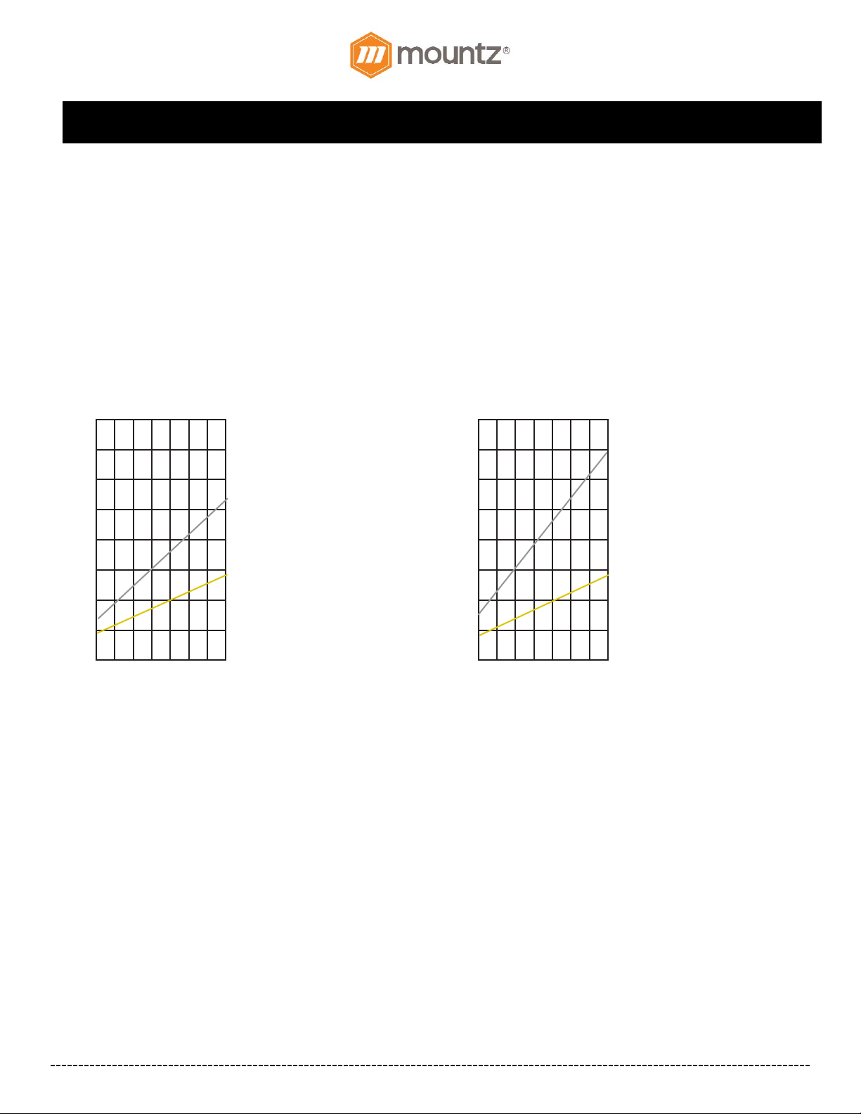
These charts are meant to be used as guidelines for setting the torque on the BF-Series electric screwdrivers. The
drivers have a torque scale on the torque adjustment nut showing reference numbers. These numbers determine the
approximate torque setting. Refer to the charts to determine the reference number setting for your torque requirement.
How to Read the Torque Charts
Torque ranges (lbf.in) approximate tightening torque, operated on 30V. Figures below each chart indicate scale setting
on the tool. Some drivers have more than one spring. Select the appropriate spring to achieve the desired torque setting.
BF060, BFS060, BFT060
1 2 3 4 5 6
Torque Scale
1
2
3
4
5
6
7
8
lbf.in
7
N (Natural)
Torque Range
1.3-5.2 lbf.in
BF080, BFS080, BFT080
1 2 3 4 5 6
Torque Scale
1
2
3
4
5
6
7
8
lbf.in
7
B (Bronze)
Torque Range
0.9-1.7 lbf.in
S (Silver)
Torque Range
1.4-6.9 lbf.in
G (Gold)
Torque Range
0.9-2.8 lbf.in
Torque Scale Torque Scale
Page 15
BF-Series (BF060, BF080 & BF120 models) Operation Instructions
Corporate Headquarters: 1080 North 11th Street, San Jose, CA95112 Phone: (408) 292-2214 Fax: (408) 292-2733
www.mountztorque.com
Page 15
Torque Charts (Continued)
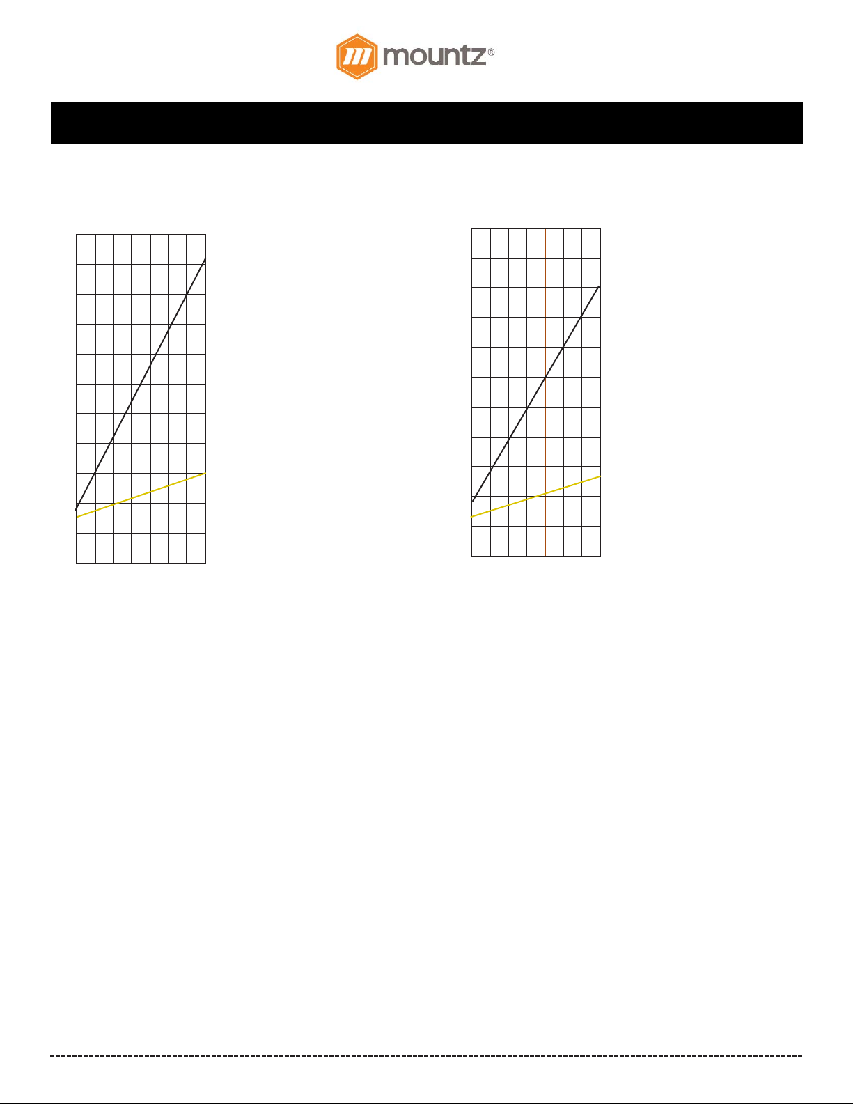
BF120 & BFT120
1 2 3 4 5 6
Torque Scale
1
2
3
4
5
6
7
8
lbf.in
7
K (Black)
Torque Range
2-10.4 lbf.in
9
10
11
G (Gold)
Torque Range
1.7-3 lbf.in
BFS120
1 2 3 4 5 6
Torque Scale
1
2
3
4
5
6
7
8
lbf.in
7
K (Black)
Torque Range
2-9.1lbf.in
9
10
11
G (Gold)
Torque Range
1.7-3 lbf.in
Page 16

BF-Series (BF060, BF080 & BF120 models) Operation Instructions
Corporate Headquarters: 1080 North 11th Street, San Jose, CA95112 Phone: (408) 292-2214 Fax: (408) 292-2733
www.mountztorque.com
Page 16
Testing Power Tools:
1. Application Method: Use a torque analyzer in “Peak Mode” with a rotary transducer between the power tool and the actual
application. This is the best way to test since you are using the actual joint as the test station. You will see the actual
torque applied to the fastener. Caution: Variances in tool performance may occur do to the addition of the rotary transducer.
2. Simulated Method: Always use a quality joint rate simulator (run down adapter) with a torque analyzer when testing power
tools in a simulated application. Use Joint rate and Breakaway methods to obtain most accurate torque readings in a
simulated rundown.
Care
1. The BF-Series screwdrivers are a precision torque control instrument and should be handled with care at all times.
2. Only use the transformers listed in the Mountz catalog or website for appropriate BF-Series driver model (If you have any questions
regarding the appropriate transformer set-up, contact Mountz Customer Service Department).
3. Operate under safe conditions. Do not place in operation where such objects as hair, strings, clothing, etc. can become
tangled in the rotating bit.
4. Keep away from moisture. Never use in high humid, moist or damp environment.
Mountz Calibration & Repair Services
Mountz Inc. features an experienced calibration and repair staff. Our trained technicians can calibrate and repair most any tool.
Mountz provides rapid service with quality that you can trust as we offer two state-of-the-art calibration lab and repair facilities that can
calibrate up to 20,000 lbf.ft.
Since 1965, Mountz’s in-depth knowledge of torque is reflected in our tool’s craftsmanship and our ability to provide solutions to both
common and uncommon torque applications. We perform calibrations in accordance with ANSI/NCSL-Z540. Mountz is dedicated solely to the manufacturing, marketing and servicing of high quality torque tools.
Tool Service & Repair Capability
- Torque Wrench Calibration: Click Wrench, Dial Torque Wrench, Beam Wrench, Cam-Over & Break-Over Wrench
- Torque Screwdrivers: Dial, Micrometer, Preset & Adjustable
- Torque Analyzers/Sensors: All brands
- Electric Screwdrivers: All brands
- Air Tools: All brands
Impact Wrenches, Drills, Pulse Tools, Grinders, Percussive Tools,
Air Screwdrivers, Nutrunners, DC Controlled Nutrunners
- Torque Multipliers: All brands
Mountz Service Locations
Eastern Service Center
19051 Underwood Rd.
Foley, AL 36535
Phone: (251) 943-4125
Fax: (251) 943-4979
Western Service Center
1080 N.11th Street
San Jose, CA 95112
Phone: (408) 292-2214
Fax: (408) 292-2733
www.mountztorque.com
 Loading...