

Page 1
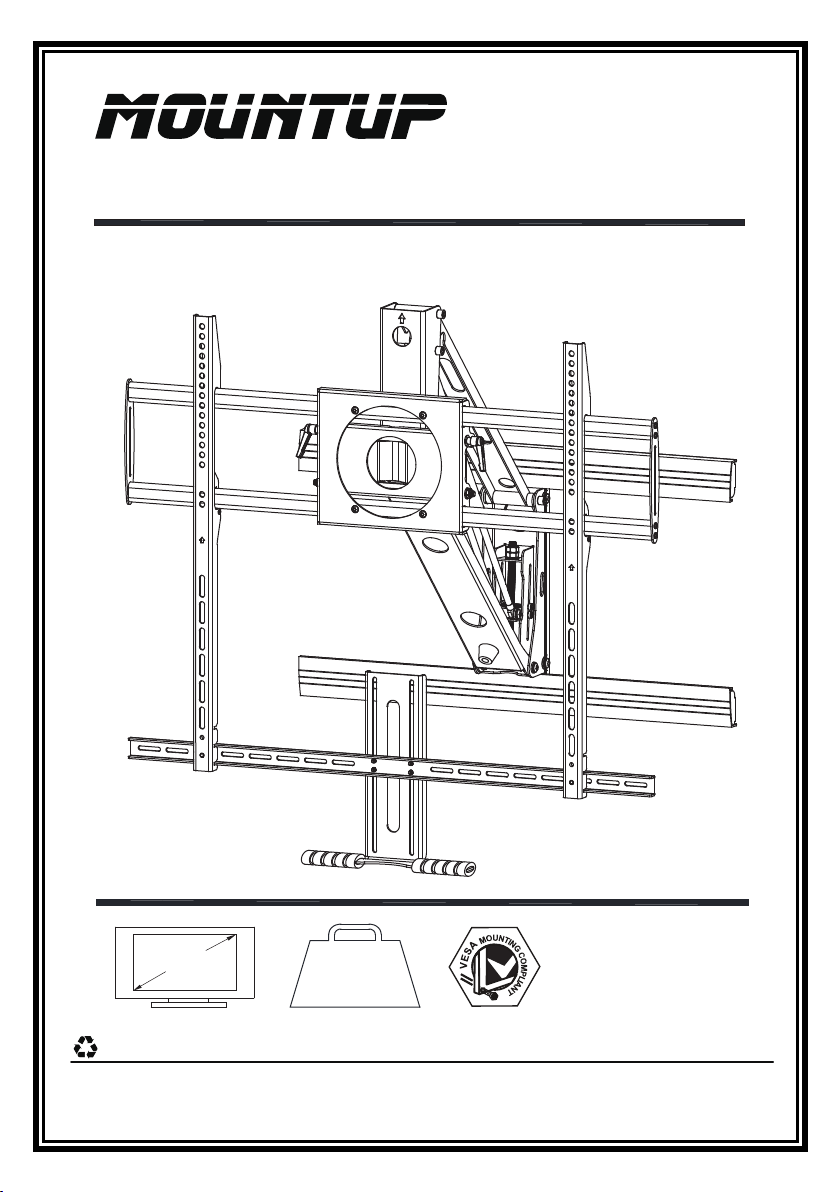
MU0021 INSTALLATION INSTRUCTION
Mantel Arm Mount
55"~100"
This bracket is made of recyclable steel.
WEIGHT:
44~143LBS
20~65KG
If you have any questions, please contact us via
Max:800x600mm/32x24"
Min: 300x200mm/12x8"
(A3)
help@jollyholding.com
Page 2
WARNING
Be sure to read this entire manual thoroughly and you fully understand all the
•
instructions and warning before attempting to begin your installation.
Sufficient expertise is required for installing of this product. Be sure to subcontract the
•
installation to a qualified person. Ensure special attention to safety is paid during
installation. MOUNTUP mount is not liable for any damage or injury caused by
mishandling or improper installation, or by installing anything other than the specified
product.Your statutory rights, (if any) are not affected.
If the safety precautions are not observed or the product is used incorrectly, it may
•
result to serious injury or damage to your wall and TV.This instruction manual shows
the correct handling of the product and important precautions necessary to prevent
accident. Be sure to read this manual thoroughly and use the product correctly.Keep
the manual available for future reference.
Ensure your hands and fingers stay clear from the adjustable moving mechanics at
•
the back of the bracket. This is
children when this product is in use.
This product is supplied with small parts for installation. For your children’s safety
•
please keep out of reach of children at all times.
•
This product should only be installed by someone who has a basic knowledge of
building construction,installations and fully understands these instructions.
Made sure that the supporting surface will safely support the combined load of the
•
mount,the display and all attached hardware and components.
This wall bracket will supporting displays(LCD,Plasma).The maximum load capacity
•
is 143 pounds.
If mouting to a wall of wood stud construction,be sure that mounting bolt are anchored
•
to the center of the studs,When installing the TV mount on a concrete wall, the wall
must be at least 8”(203mm) thick with a minimum compressive strength from 2500 to
3000 psi(17.2 to 20.7 MPa),the concrete wall must meet ASTM C39.When installing
the TV mount on a cinder block wall, the cinder blocks must meet ASTM C216
specifications and have a minimum nominal width of 8”(203mm). Be sure to mount in
a solid part of the block,generally 1”(25 mm) minimum from the side of the block.
Do not drill into mortar joints! If plaster/drywall is thicker than 16mm, custom fasteners
must be supplied by the installer.
Always have someone assist you to lift and position your equipment.•
to avoid your fingers getting trapped. Please supervise
Tighten screws and bolts firmly,but do not over tighten.Over tightening can damage the
•
items and greatly reduce their ability to hold.Please refer to suggested torque values
where applicable in these instructions.
Screws must be tightly secured,but do not overtighten any screws(especially the four
•
Hex Bolt Screws M8x63.5mm) or damage can occur and product may fail.
2 of 16
Page 3
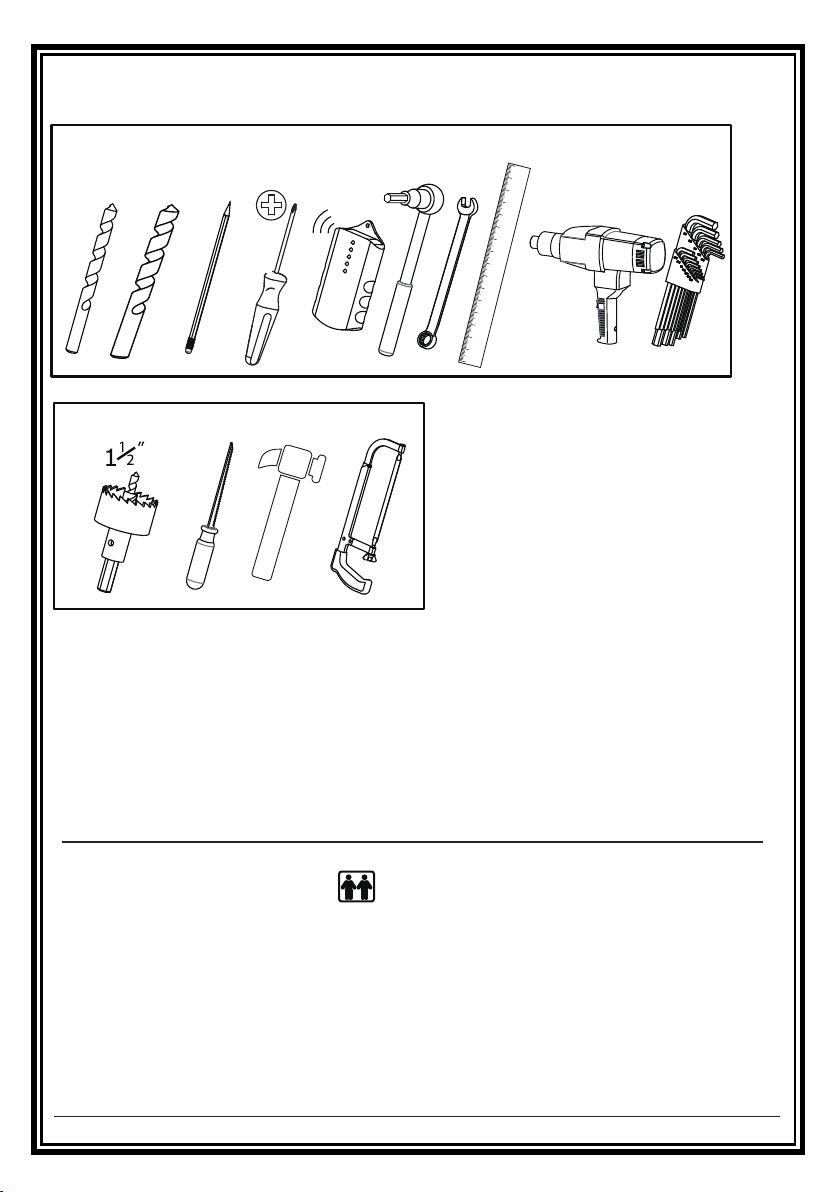
Tools Needed for Assembly
Required Tools
3/16” 3/8”
Optional Tools
Before you begin, please verify that all components are included and undamaged.
If any parts are missing or damaged,contact Product Supplier,Never proceed with
missing or damaged parts!
Lay out all components and make sure you identify that each one has a match
in the diagram.Some of the parts included will not be used during installation.
Do not proceed if you do not understand and indentify all of the components.
Table of Contents
Parts List............................................................................................................................................4
Critical requirements of the installation ...................................................................................5
Installation of the bracket................................................................................................................6-8
Installation of Screen.....................................................................................................................9-11
Adjustment of the spring pressure....................................................................................................12
Leveling adjustment .........................................................................................................................13
Tilting angle adjustment .................................................................................................................14
Product dimensions .........................................................................................................................15
Cauton and Maintenance
.................................................................................................................16
3 of 16
Page 4
D
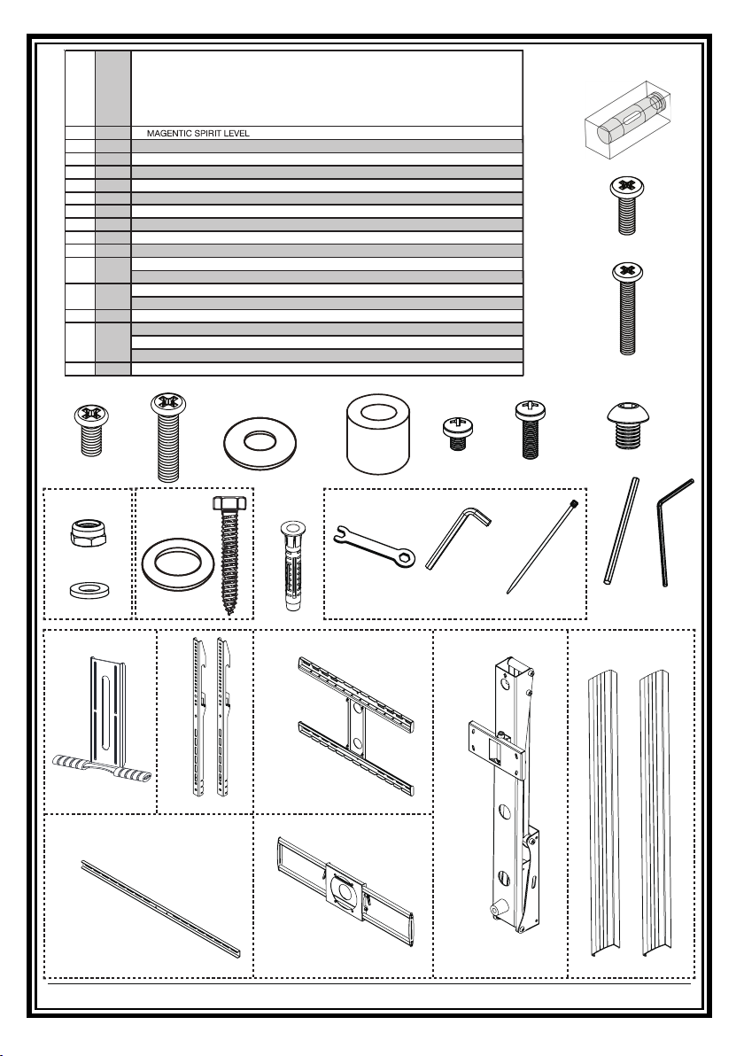
Before you b egin, mak e sure all pa rts shown are incl uded
with your product.
Parts may appear slightly different than illus trated.
Parts List
Description
A
philips pan head screw
B
philips pan head screw
C
philips pan head screw
D
philips pan head screw
E
F
washer(1)
spacer
G
philips pan head screw
H
philips pan head screw
I
J
K
L
M
N
O
allen pan head screw
Non-slip nuts
washer(1)
washer(2)
Hex bolt screw
Expansion pipe
spanner
Hexagon wrench
Cable ties
Hexagon wrench
F
G J
1
15x15x40
4
4
4
4
4
4
6
2
4
4
4
4
4
4
1 M10
1 M5
2 L150
2 M8
M6x12
M6x25
M8x12
M8x25
6.2x16x1.5
17.0x9.0x14.0
M6x8
M6x25
M8x10
M6
6.2x16x1.5
8.2x2.0x16
M8x63.5
M10x60
H
A
B
C
IE
1
K L
Non-slip nuts(x4)
washer(x4)
AA
2
BB
M
CC
hook(x2)handle(x1)
N
Spanner
M10(x1)
wallboard(x1)
DD EE
front-panel(x1)connecting rod(x1) bracket(x1)
4 of 16
Hexagon wrench
M5(x1) Cable Ties(x2)
FF GG
O1
O2
Hexagon wrench
M8(x2)
Wall panel cover(x2)
Page 5
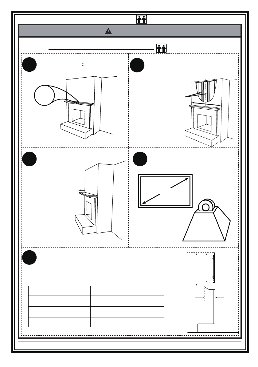
CRITICAL requirements of the installation
WARNING
• Make surethatthe supportingsurfacewillsafelysupportthecombinedloadof theequipmentand allattachedhardwareand
components, Bracket installation need two people together to complete.
Temperature at the front edge of mantle should
never exceed 110° F ( 43
1
) .
110°F
MAX.
Mantle must not extend from mounting surface
more than 16 inches.
3
16 inches
MAXIMUM
If the main wall is wooden,There must be at least 2 studs
available for mounting .If the main wall is concrete or brick
wall,please refer to th e S4 installa tion points.
2
the wall covering must not exceed 5/8 inches thick.
2 STUDS
(This two studs need along the
mantel center symmetric,and
the center distance between
two studs not more than 25”)
TV weight must be between 44~143Ibs(20~65kg)
and have a screen size from 55” to 100”.
4
TV Owner's
Consult Manual for verification.
from 55” to 100
”
C
L
WEIGHT:
44~143Ibs
(20~65kg)
Mind you,
The space above the mantle must be taller than the wallboard.
The required space depends on how far out the mantle extends.
5
Refer to chart below and add this additional height to wallboard
height to determine if space is tall enough.
If mantle extends:
Less than 8 inches
8 - 11 inches
11 - 13 inches
13- 16 inches
This is required space height:
TV wallboard height plus 5 inches
TV wallboard height plus 6 inches
TV wallboard height plus 7 inches
TV wallboard height plus 8 inches
5 of 16
Mantle
Extends
Space height
Wallboard height
Page 6
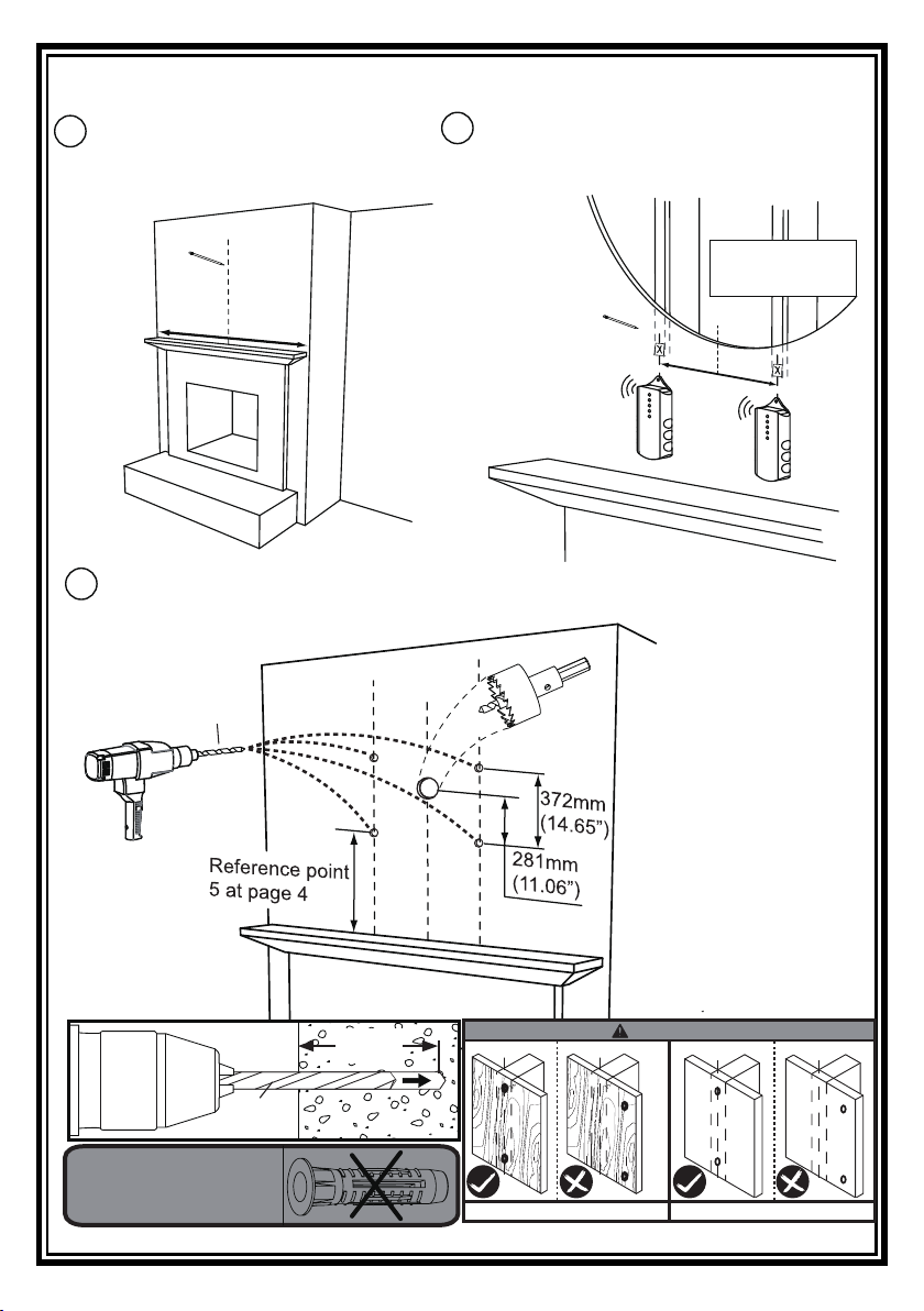
Installation of the bracket
Measure the centerline of the mantle. Mark
S1
with tape on the wall.
C
L
S3
Please reference point 5 at page 5 to punch, please make sure that the four
mounting holes don’t have too big deviation.
C
L
C
6mm(3/16”)
Locate at least two studs with a stud finder. Locate the
S2
center of these studs by using a sharp awl or finish nail
poked through the drywall to locate each edge. Lag bolts
must be installed into the CENTER of the studs.
C
L
C
L
L
Cutout shown
for reference
C
L
C
L
6mm
(3/16”)
For the wood stud installation,
you MUST NOT use the expansion pipes we provided in M.
68mm
(2.7”)
6 of 16
CAUTION
CL
plywood wall wood stud wall
CL
CL
CL
Page 7
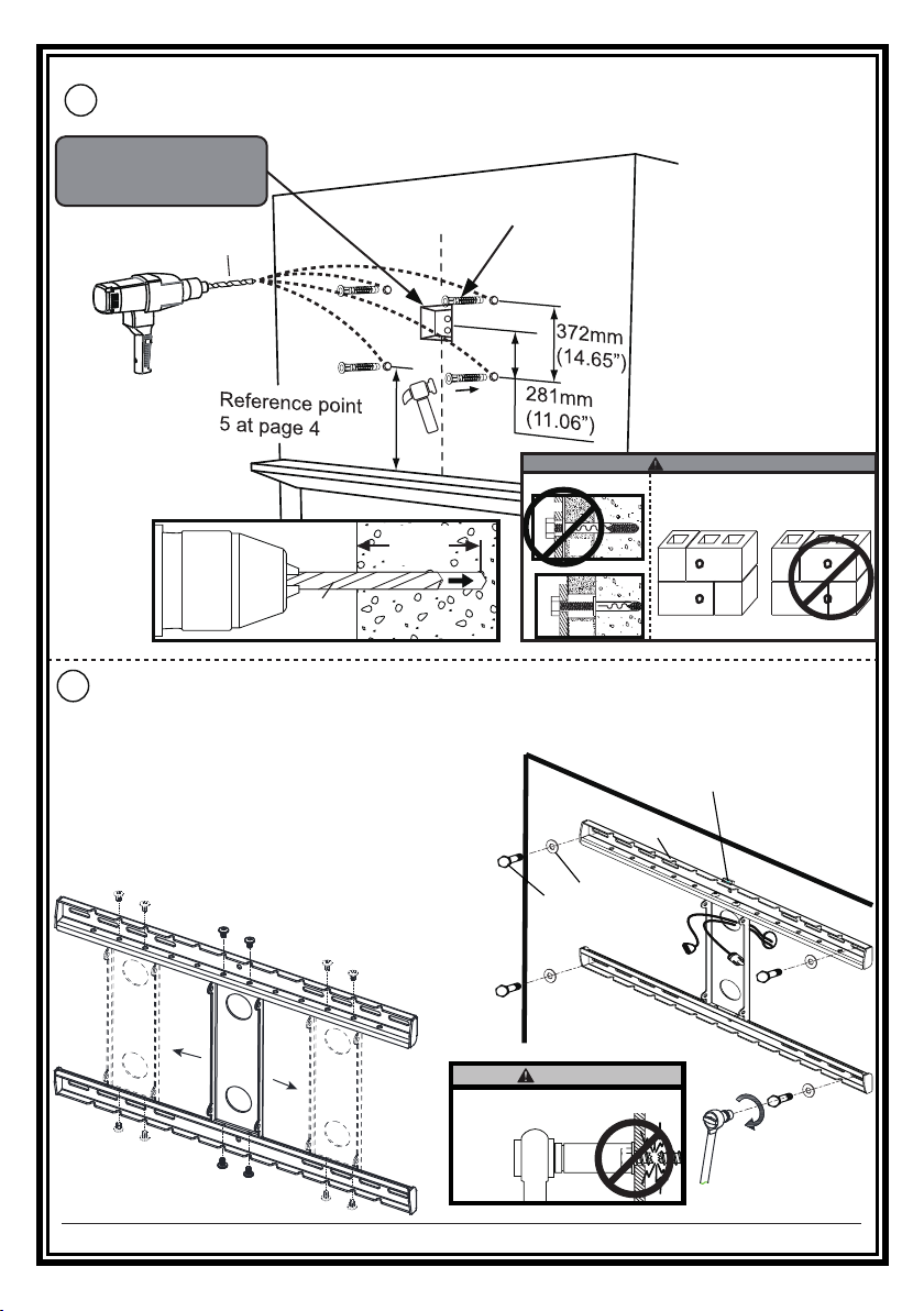
Installation of the bracket
Please reference point 5 at page 5 to punch,If the main wall is concrete or brick wall,
S4
you must use the expansion pipe we provided in M.
In order to have a better installation,it is necessary to inlay one
wire cassette on the wall.
10mm(3/8”)
C
L
M
CUTAWAY VIEW
68mm
(2.7”)
10mm
(3/8”)
Install wallboard(CC) using Hex bolt screws and washers(L).please let the
S5
pre-set wire go through the hole as illustrated in the picture. Tighten the
wall plate
wall plate
plaster/
dry wall
plaster/
dry wall
INCORRECT
CAUTION
Do not drill into mortar joints!
concrete
CORRECT
concrete
Hex bolt screws until they are pulled firmly against the wallboard.
NOTE:
If the wood studs are off-center above the
(magentic spirit level)
A
mantel, the center steel plate of wallboard(CC)
can be reassembled to left or right for TV
CC
centering, then tighten securely. There are
different hole positions on the wall plate.
L
L
CAUTION
Don't over tighten!
7 of 16
Page 8
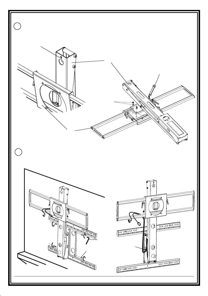
Installation of the bracket
Take out K/EE/FF/N(spanner M10) from the packaging , installation as
S6
illustrated in the picture.
keep the up direction uniform
FF
(spanner M10)
K
EE
Take out N/J from the packaging ,lock the four allen pan head
S7
screws(M8x10) with Hexagon wrench in N,then use cable ties
in N to tie up the wires,as is shown in the pictures below.
N
N
(Hexagon wrench)
(screw M8x10)
J
8 of 16
N
(Cable ties)
Page 9
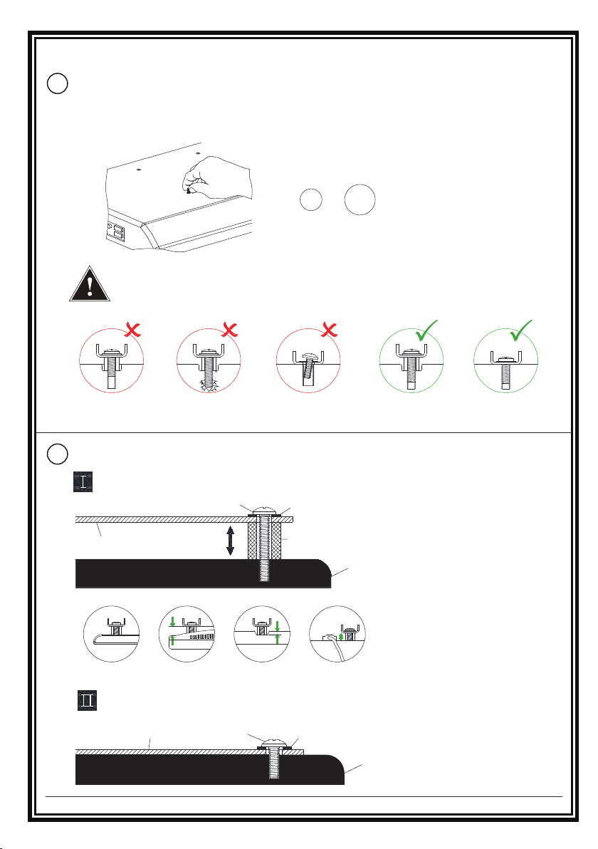
Installation of Screen
Select TV Screws
S8
Thread screws by hand into the threaded holes on the back of your TV to select
which screw diameter fits your TV.
When attaching brackets to the flat screen,be careful not to over tighten
screws and be sure that screws do not bottom out in the mounting holes.
S9
Need Spacer or NOT?
Yes,choose the appropriate screws, washers and spacers for your TV
Hook
Long Screw
M6
Washer
Spacer
M8
Correct CorrectToo Long Not VerticalToo Short
TV back
Highly recommended to add spacers for more spacing between wall mount and TV.
No,just choose the screws and washers
Hook
Short Screw
Washer
TV back
9 of 16
Page 10
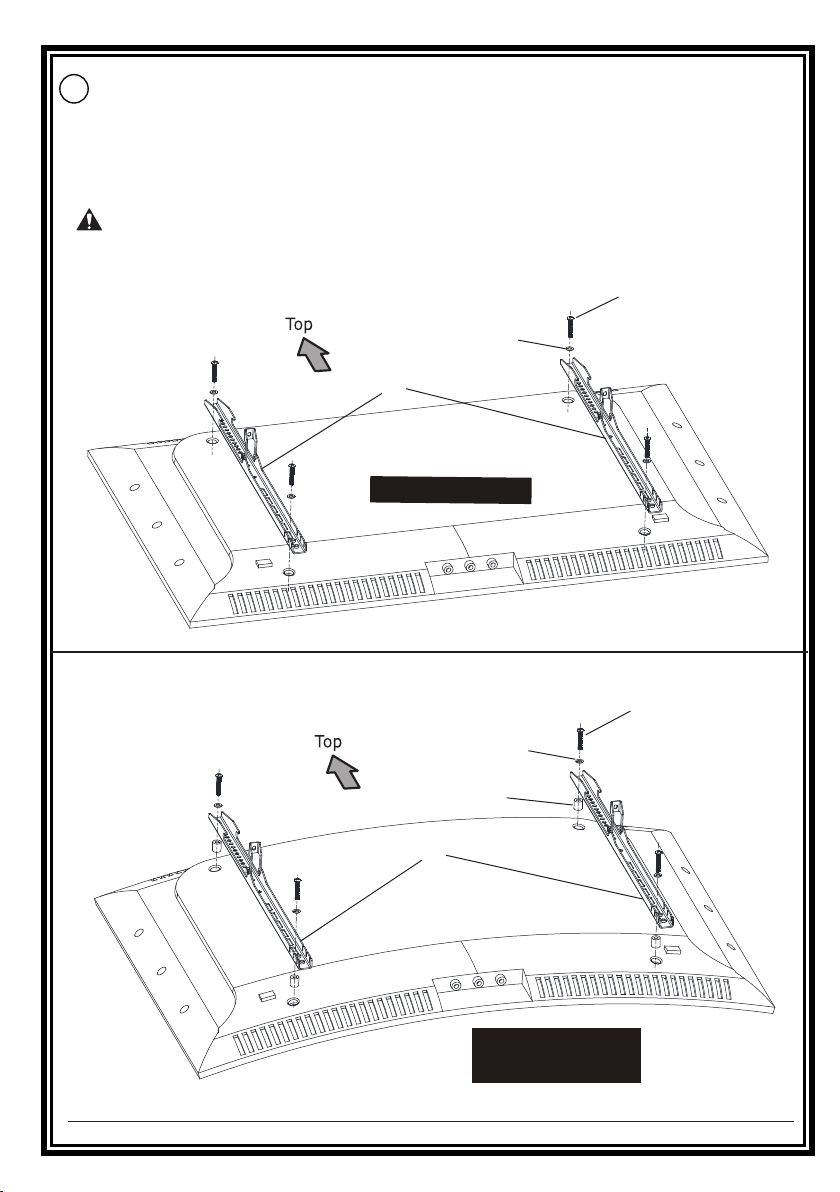
S10
Attach the Hooks
Position your hooks over your TV hole pattern - making sure the hooks are centered
and level over the TV hole pattern.
Secure the hooks using your screw/washer/spacer selection:
(a) for Flat Back
(b) for Round Back/Extra space
CAUTION:
Ensure hook is securely fastened before moving on to the next step.
B/D
(D don’t need F)
F
(only for B)
BB
(a) Flat Back
BB
10 of 16
F
(only for C)
G
(b) Round Back /
Extra Space
C/E
(E don’t need F)
Page 11
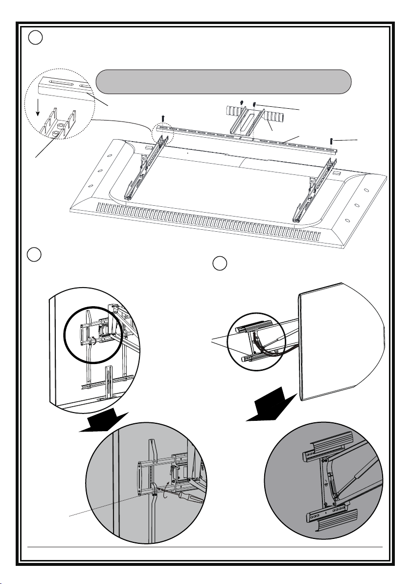
S11
Attach the Handle
Take out H/I/AA/DD from the packaging,according to the size of the TV,adjust to the
appropriate location,as shown in the picture below,then lock with cross screwdriver.
Note:Take care not to damage the TV when putting the
connecting rod(DD) into the small gap of the hook(BB).
DD
BB
Lift the TV,through hooks for hanging
S12
onto the bracket panel,then press the
safety locks on the hooks and fix it
with the screws(H).
Hx4
(screw M6x8)
AA
DD
Take out GG from the packaging,
S13
buckle it to the wall plate.
GG
Ix2
(screw M6x25)
Hx2
(screw M6x8)
11 of 16
Page 12
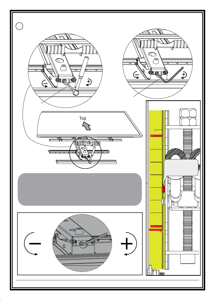
adjustment of the spring pressure
Adjust the spring pressure to the appropriate level with the socket wrench and O1
S14
or O2 (the hexagon wrench M8 that we provided).
OR
O2
O1
KG/LBS
18.0/40.0
!
STOP LINE
24.0/52.9
32.0/70.5
Refer to this
above cylinder
40.0/88.2
as a pointer
Adjustable the bracket’s constant force
Attention: The weight of the TV set in the weighing range
A:The TV sets can be hovering at any height, don not need to adjust.
B:The TV sets up, turn to “ - ” until free hovering.
C:The TV sets down, turn to “ + ” until free hovering.
48.0/105.6
56.0/123.4
60.0/132.2
Reduce the
constant force
Increase the
constant force
12 of 16
70.0/154.0
!
STOP LINE
ATTENTION
suitable posi
of th
is fo
rbidd
e
scale,
en!
t
excessiv
i
o
n with
i
e
n the sco p
adjustme
n
e
t
please
adjust
th
e gas
s
prin
g
int
o
Accor
din
g
to d
ifferent load weight,
Page 13

!
WARNING:
Do Not put hands into Lifting Mechanism.
The power of the Lifting Mechanism can cause bodily injury!
TV leveling adjustment (-5°/+5°)
If needed,loosen 4 leveling nuts on the rear of TV plate by maximum 2
S15
turns with the N(spanner), adjust to level, and retighten to secure.
±5°
(spanner M10)
13 of 16
N
(spanner M10)
N
Page 14
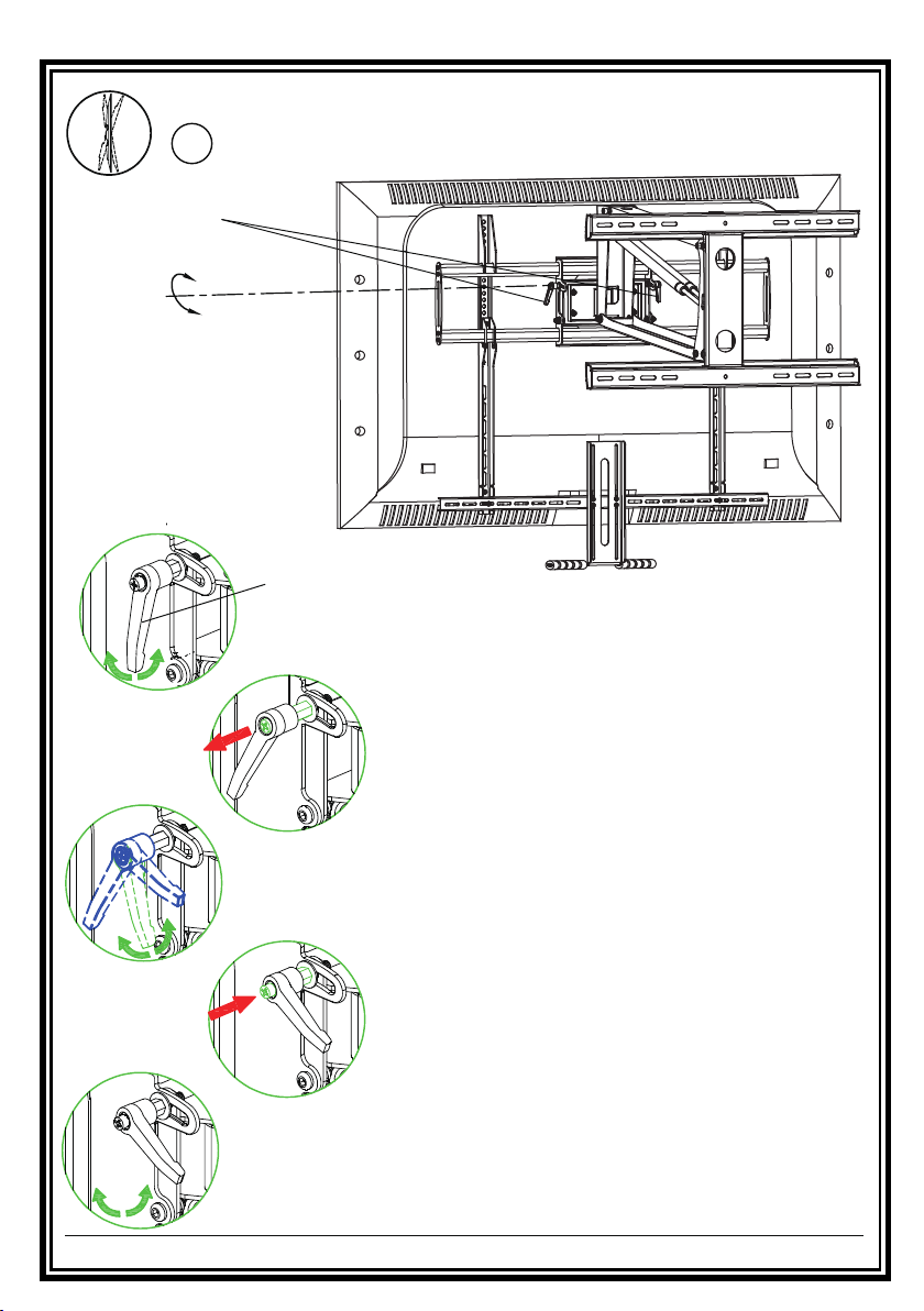
Tilting angle adjustment (-15°/+3°)
Loosen handles, adjust TV to your desired position,
S16
then tighten handles.
Handles
+3°
-15 °
How to tighten or
loosen the handles
Handle
① Turn handle (loosen or tighten)
until stopped by mount.
② Pull out and hold the handle.
③
Turn the handle in the opposite direction.
④
Push and release the handle.
Turn handle again to tighten or loosen.
⑤
14 of 16
Page 15
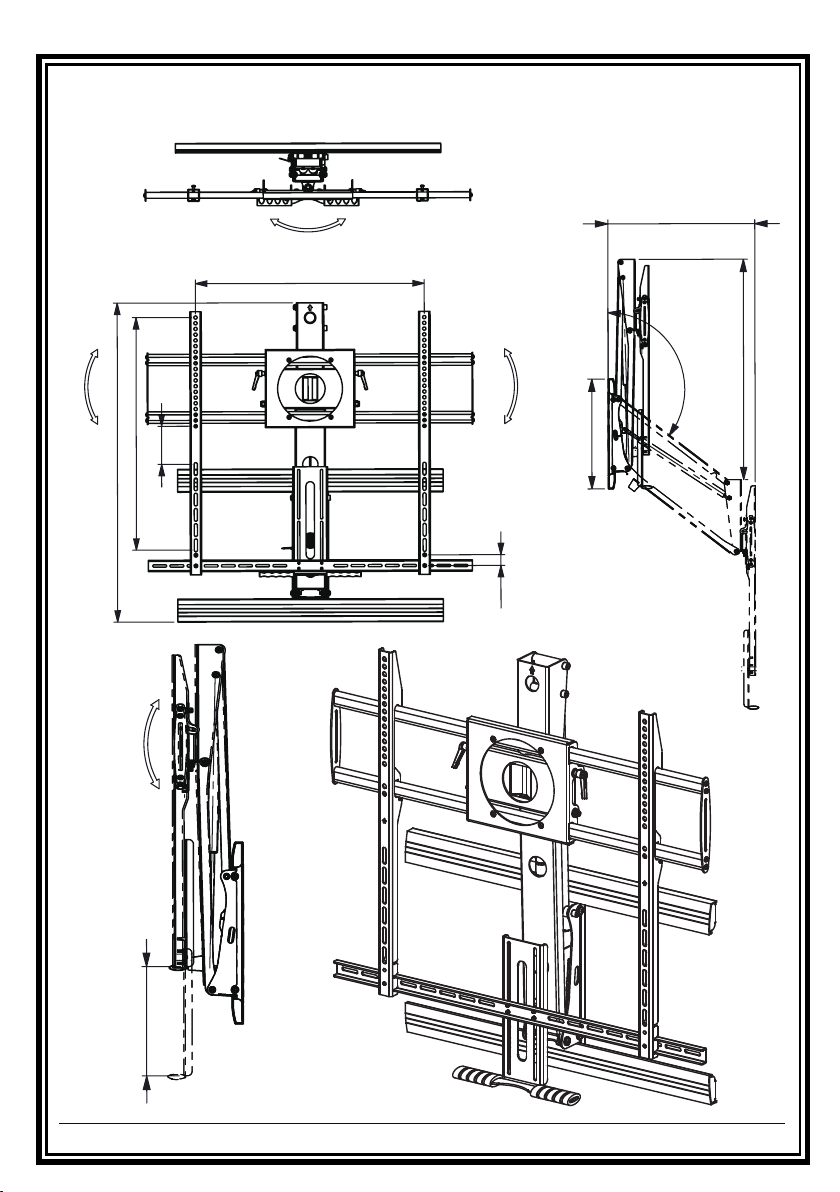
PRODUCT DIMENSIONS
swivel:±30°
MAX820
°5±:level
mm0.016
mm7.638
0.001
from 150mm to 536mm
MAX127°
°5±:level
0.82
mm8.004
mm008 OT XAM
°
°
-15 ~+3:tlit
mm042 OT XAM
15 of 16
Page 16
please use the cloth stained with water to wipe it.
Don’t disassemble the product randomly.
Do not use strong acidic or alkaline liquid to wipe the product.
Never allow children to climb,stand,hang or play on any part
of Mantel Arm Mount.
Check that the mantel arm mount is secure and safe to use
at regular intervals(at least every three months).
16 of 16
 Loading...