

Page 1
En glish
Installation Instruction
UNPACKING INSTRUCTIONS
! Carefully open the carton, remove contents and lay out on cardboard or other
protective s urface to avoid damage.
! Check package c ontents again st the Suppli ed Pa rts List in t he next page to assure
that al l com ponents we re receive d und amage d. Do not use damaged or de fective
parts.
! Care fully read all inst ructi ons before attemp ting installation.
IMPORTANT SAFETY INFORMATION
! Install a nd operate this device with c are. Please read this inst ruction befo re
installati on, and carefully follow all instruc tions contained herein . Use proper safety
equipment du ring in stallation.
! Pl ease call a qualifie d ins tallation contractor for help if you don't understand thes e
directions o r have an y doubts about the sa fety of the install ation .
Do not use this produc t for any p urpose or in any configuration not expli citly specified
in this in struction. We hereby discla ims any and all liabi lity for inju ry or da mage
arising from i ncorr ect assembly, incorre ct moun ting, or incorrec t use of this product.
1
Page 2
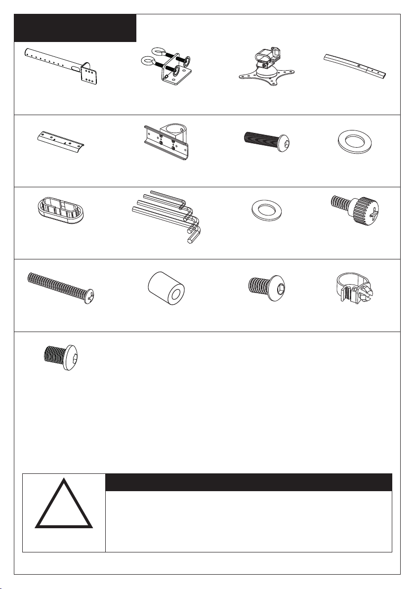
Su pp li ed Par ts List
(1) 48mm Pole- a
(1) Arm Connect
Part-e
(2)Arm Plast ic
Cover-i
(8)M4x30 Bol t-m
(2)M10x15 Bo lt-q
(1) Disconnected
“C” Clamp-b
(1) Arm Clamp-f (4)M6x25 Bol t-g (4)M6 Wash er-h
(1)Allen Key -j
(8)M4 Space- n (2)M8x10 Bol t-o (2)Wire Clip -p
(2) Side Vesa Pla te
with Slip Set- c
(16)M4 Was her-k
(2) Short Arm-d
(8)M4x12
Thumb Bolt-l
!
WARNING
CAUTION!
This monitor desktop mount must be securely
attached to the horizontal desk. If the mount is
not properly installed it may fall, resulting in
possible injury and/or damage.
2
Page 3
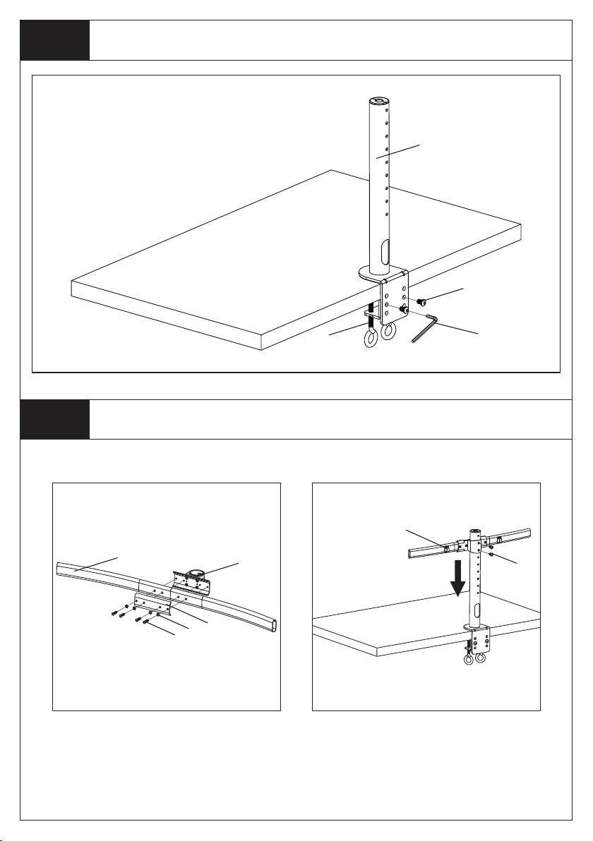
St ep 1
The depth of “C” clamp can be changed in
three positi ons. Choose the proper dep th
acco rdin g t o t he thi c kne s s of you r
de sk top. Co nn ect i t by 2p cs M10x15
bolts(q), us ing the supplied Allen Key( j).
Install the “C” Clamp According to the Desktop Thickness
a
q
St ep 2
Assemble the curved arm sets as th e
di ag ram a bo ve, faste n the M 6x 25
Bolt(g) by pro vided Al len Key(j).
Assemble the Arm Sets and Install it on the Pole
d
h
g
f
e
b
j
p
o
Insert the curv ed arm sets to pole,
fasten the M8x10 Bolt(o) by provi ded
Allen Key(j) . Install the Wire Clip(p) .
3
Page 4
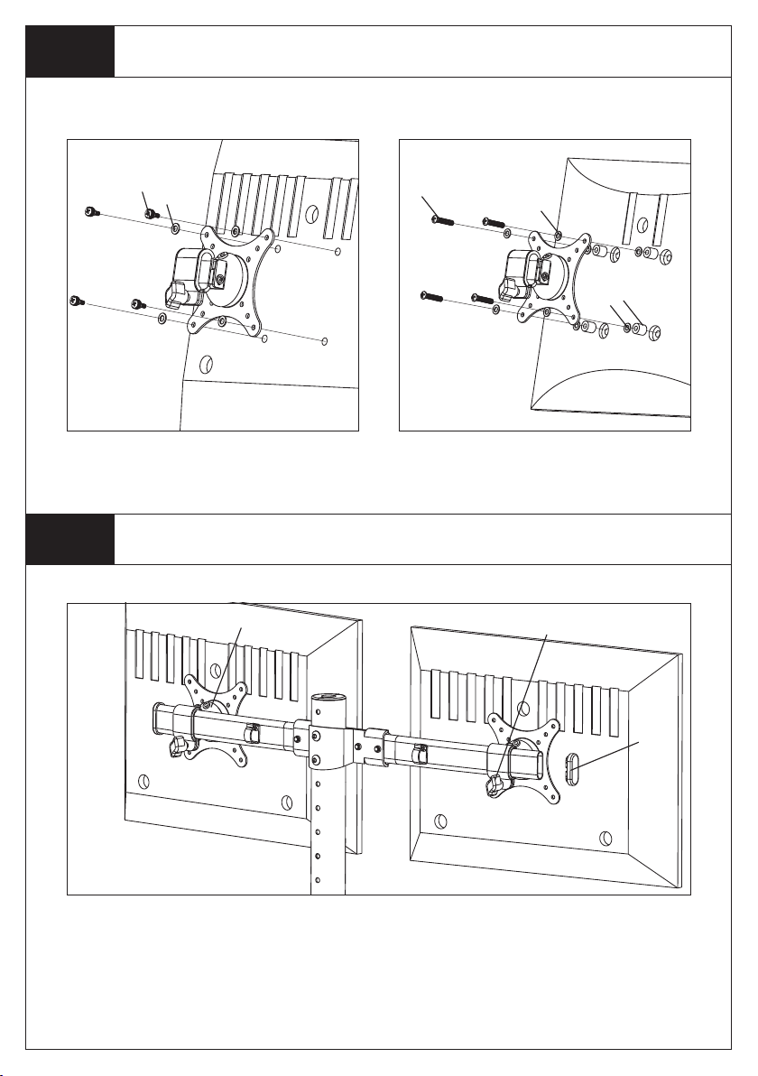
St ep 3
Mount the Monitor to VESA Plate
St ep 4
l
k
For Flat Back Monitor
For Flat Back Monitor
Attach the Monitors to Arm Sets
c
m
k
k
For Curved Back Monitor
Plastic Knob
n
i
Attaching the monit ors to the c urved arm sets, fixi ng the po sitio n by the plastic
knob. Instal l the Arm Plastic Cover -i as the a bove diagram.
4
Page 5
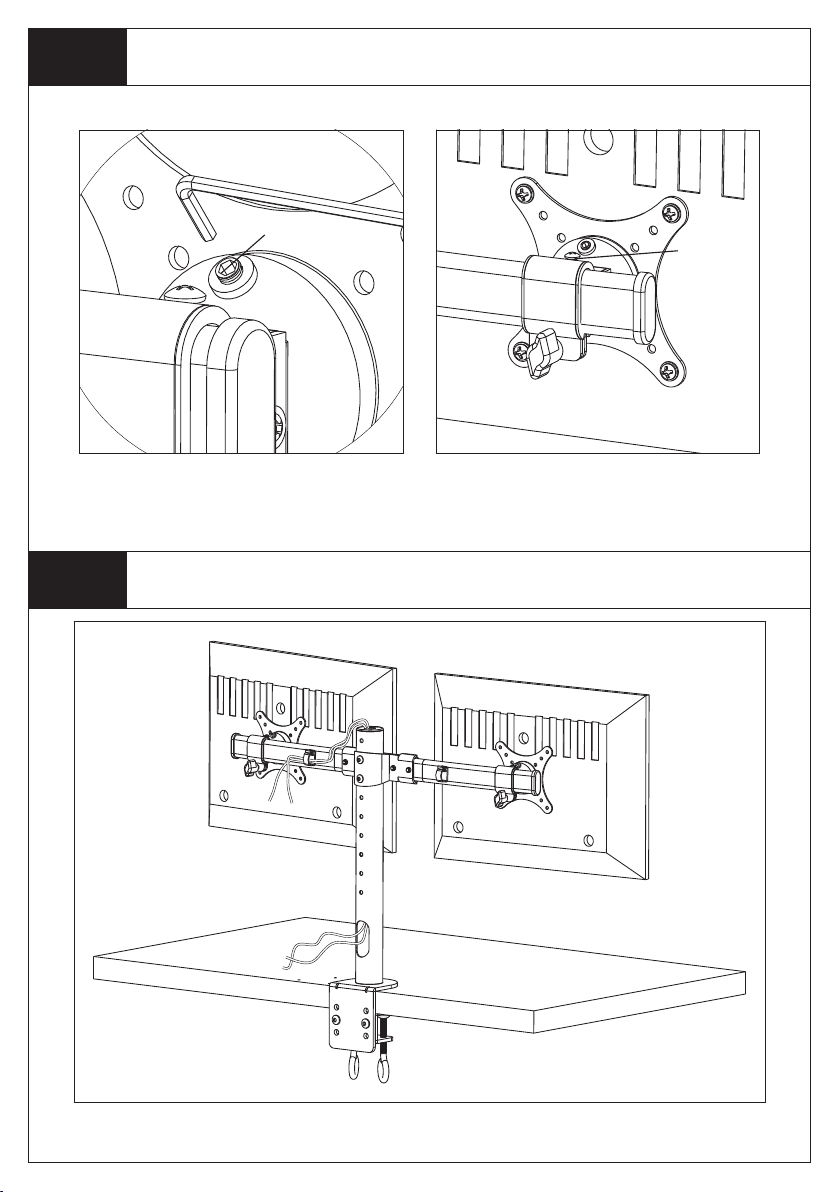
St ep 5
Adjust the Tilting Angle and the Monitors Level
grub screw
Bolt
Fasten the grub scr ew to fix the til ting
angle by provi ded Allen Key(j).
St ep 6
Manage the Wires
By fasten or loosen the bolt on the
above diag ram to adjust the level of
each monitor.
5
 Loading...