

Page 1
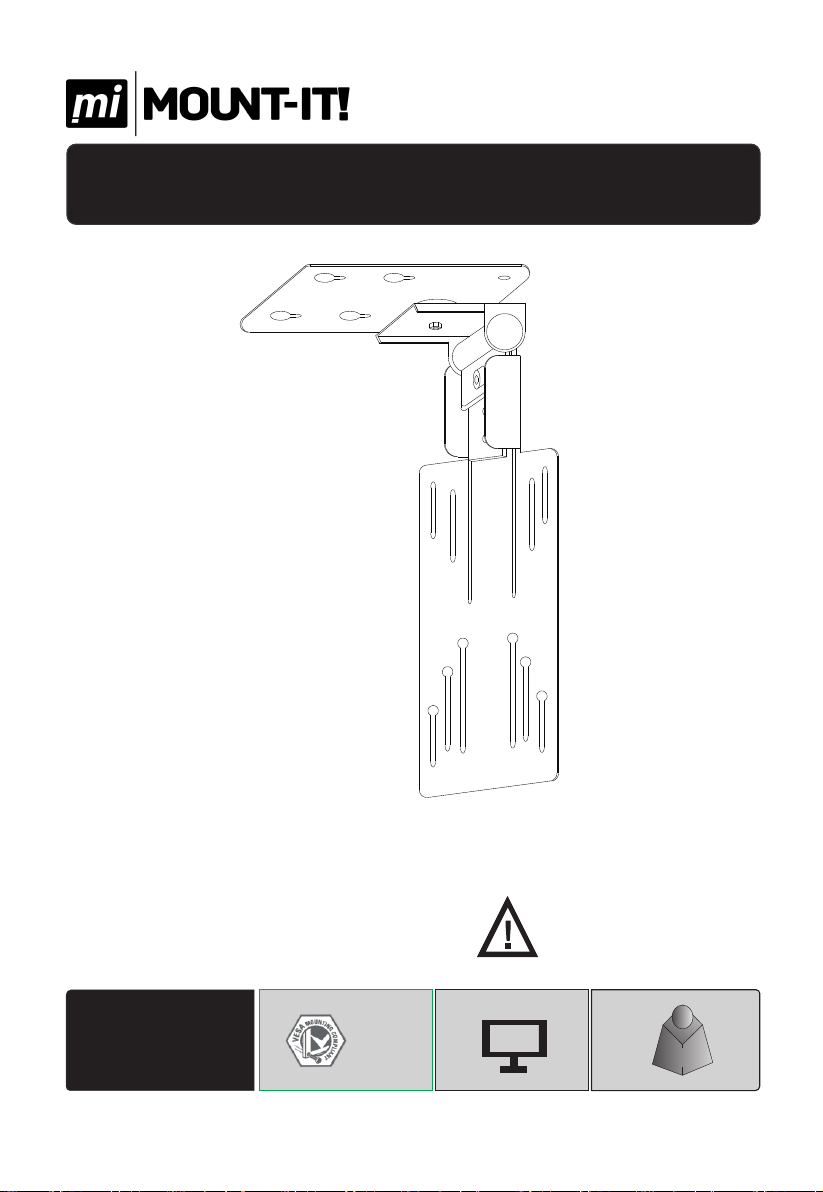
INSTALLATION MANUAL
Under-cabinet/Ceiling Mount
MI- 4200
50x50
75x75
100x10 0
CAU TION: DO NO T EXCE ED
RATE D LIS TED WE IGH T.SER IOUS
INJ URY OR P ROP ERTY D AMA GE
MAY OC CUR!
23"
MAX
8kg
(17.6 lbs)
RATED
Page 2
NOTE: R ead the e ntire i nstru ction m anual b efore y ou star t insta llati on and as sembl y.
WARNING
•
Do not be gin the i nstal latio n until y ou have r ead and u nders tood al l the ins truct ions
and warnings contai ned in th is inst allat ion she et. If yo u have an y quest ions
regarding any of the in struc tions o r warni ngs, pl ease co ntact y our loc al dist ribut or.
•
This mo untin g brack et was de signe d to be ins talle d and uti lised O NLY as s pecifi ed
in this m anual . Impro per ins talla tion of t his pro duct ma y cause d amage o r serio us
injury.
This pr oduct s hould o nly be in stall ed by som eone w
•
has basic building experie nce and f ully un derst ands th is manu al.
•
Make sure that t he supp ortin g surfa ce will s afely s uppor t the com bined w eight o f the
equipment an d all att ached h ardwa re and co mpone nts.
Always use an assista nt or mec hanic al lift ing equ ipmen t to safe ly lift a nd posi tion
•
the equ ipmen t.
•
Tig hten sc rews fir mly, but do not o ver tig hten. O ver tig hteni ng can ca use dam age to
the ite ms, Thi s great ly reduces their holding power.
This pr oduct i s inten ded for i ndoor u se only. Using this product outdoo rs coul d lead
•
to prod uct fa
ilure and personal injury.
ith goo d mecha nical a bilit y who
1
Page 3
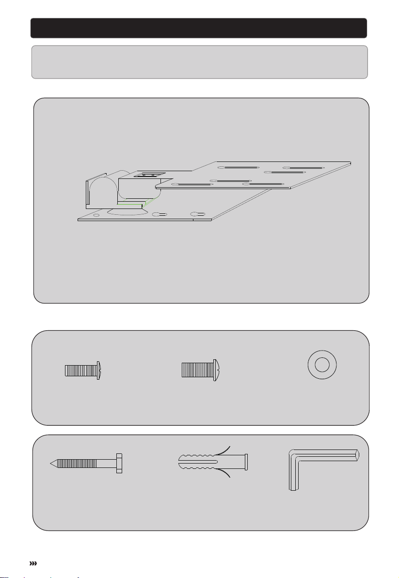
Component Ch eckli st
IMPOR TANT: Ensure tha t you h ave r ece ived all parts ac cor din g to th e com ponent checkl ist p rio r to
installa tio n. If a ny pa rts a re missing o r fau lty, tele pho ne yo ur lo cal distribut or fo r a
replacem ent .
(1) ceiling mount
Package
(4)M4x14-A
(6)ST5.5x50-B
2
(4)M5x14-A
(6)concrete anchor-B
(4)M5 washer-A
(1)Wrench-C
Page 4
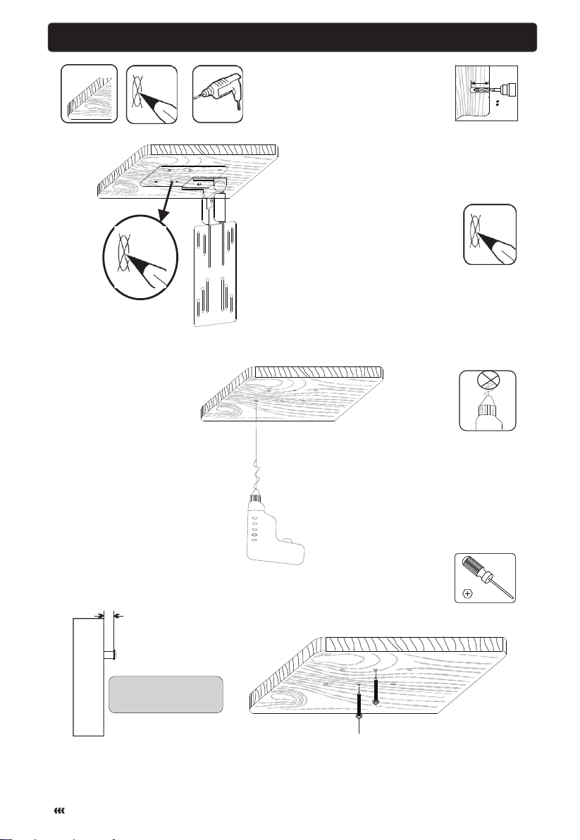
3a.Fo r Woode n Ceili ng Moun ting
Wood en ceil ing
50mm(2")
4mm
( 5/32")
1.Fin d and mar k the
exact l ocati on of
mount ing hol es.
2.Dri ll pi lot h ole s
3MM
3.Scr ew the sc rews
into th e ceili ng
Tig hte n the s cre ws
leavi ng a 3m m
space t o cei lin g
B
3
Page 5
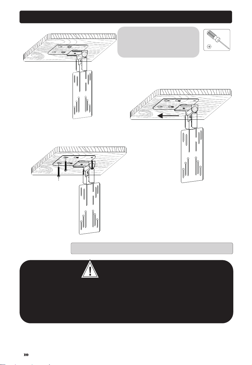
Align t he bo th ho les o f cei ling plate to
the scr ews i n cei lin g and m ove the
ceili ng pl ate u nti l the b oth screws are
seate d in sm all a rea o f tea r-drop
mount ing h ole s.
B
Fix the c eilin g plate u sing fo ur scre ws and th en tigh ten all s crews .
WARNING
• Insta llers a re resp onsib le to pro vide ha rdwar e for oth er type s of moun ting si tuati ons.
• Insta llers m ust ver ify tha t the sup porti ng surf ace wil l safel y suppo rt the co mbine d
weigh t of the eq uipme nt and al l attac hed har dware a nd comp onent s.
4
Page 6
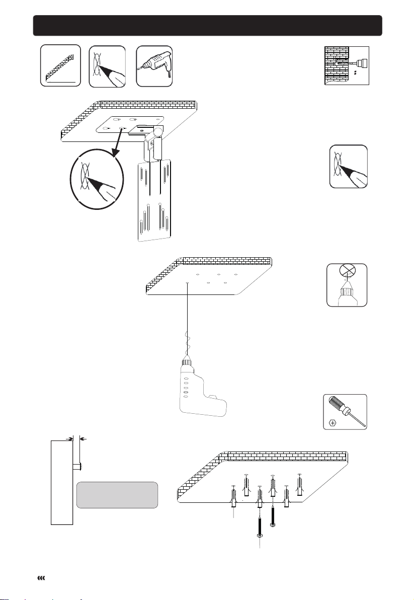
3b.Fo r Solid B rick an d Concr ete Mou nting
Soli d Brick
55mm(2.2 ")
8mm
( 5/16")
1.Fin d and mar k the
exact l ocati on of
mount ing hol es.
2.Dri ll pi lot h ole s
3MM
3.Scr ew the sc rews
into th e ceili ng
Tig hte n the s cre ws
leavi ng a 3m m
space t o cei lin g
B
B
5
Page 7
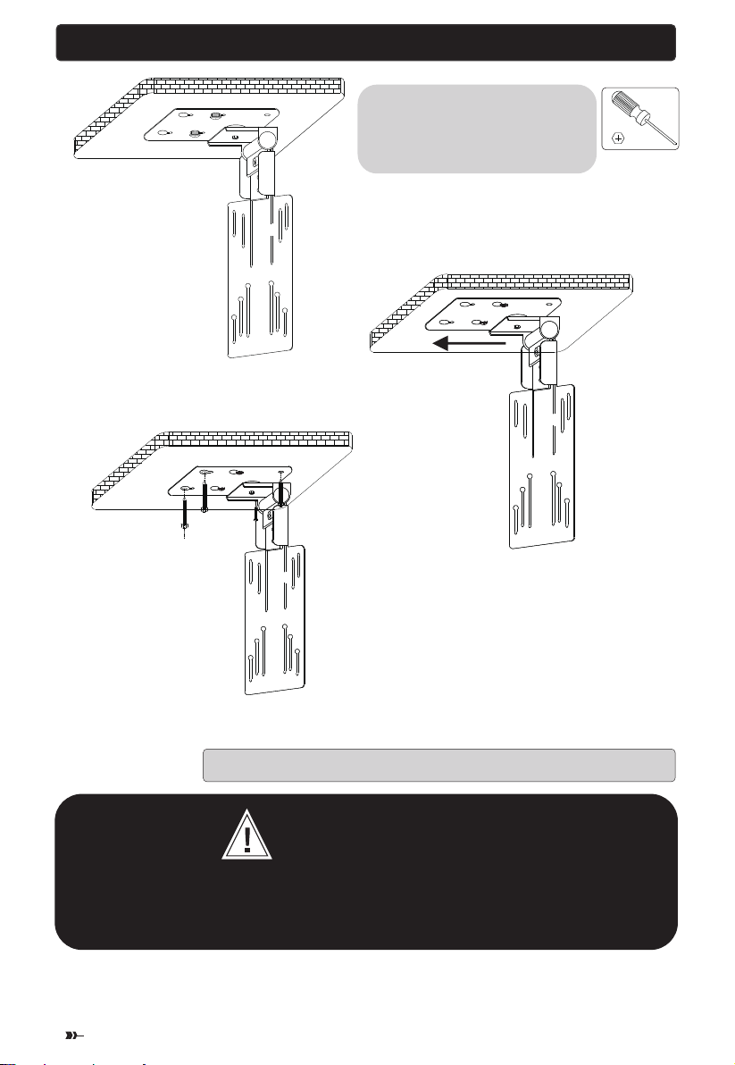
Align t he bo th ho les o f cei ling plate to
the scr ews i n cei lin g and m ove the
ceili ng pl ate u nti l the b oth screws are
seate d in sm all a rea o f tea r-drop
mount ing h ole s.
B
Fix the c eilin g plate u sing fo ur scre ws and th en tigh ten all s crews .
WARNING
Insta llers m ust ver ify tha t the sup porti ng surf ace wil l safel y suppo rt the co mbine d
weight of the eq uipme nt and al l attac hed har dware a nd comp onent s.
6
Page 8
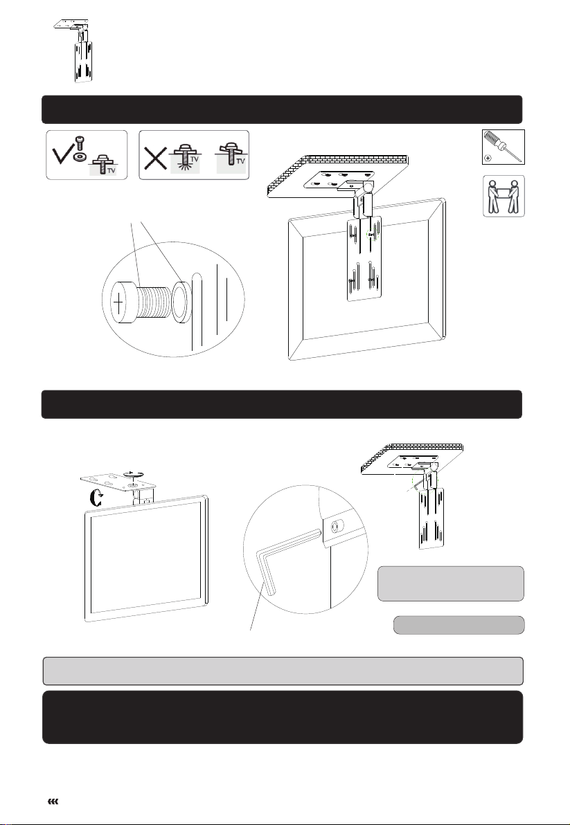
4.Attaching the Display to the VESA Plate
A
5.Adjustment
360°
0°-- -110°
Ple ase tig hten th e screw i f the
cei ling mount c an' t be sta yed
in th e desired po sit ion du ring use.
C
For s aving the sp ace , you ca n fol d the d ispl ay by p ush ing th e dis pla y back u nti l it fits in pla ce.
Mainte nan ce
• Che ck that t he br ack et is se cur e and s afe to u se at r egu lar in ter vals(at l eas t every thr ee mo nths ).
• Ple ase c ont act yo ur di str ibut or if y ou have any q ues tion s.
7
Adjust t o the d esir ed po sit ion.
Ri vi si on D at e :2 01 7/ 8/ 8
 Loading...