

Page 1
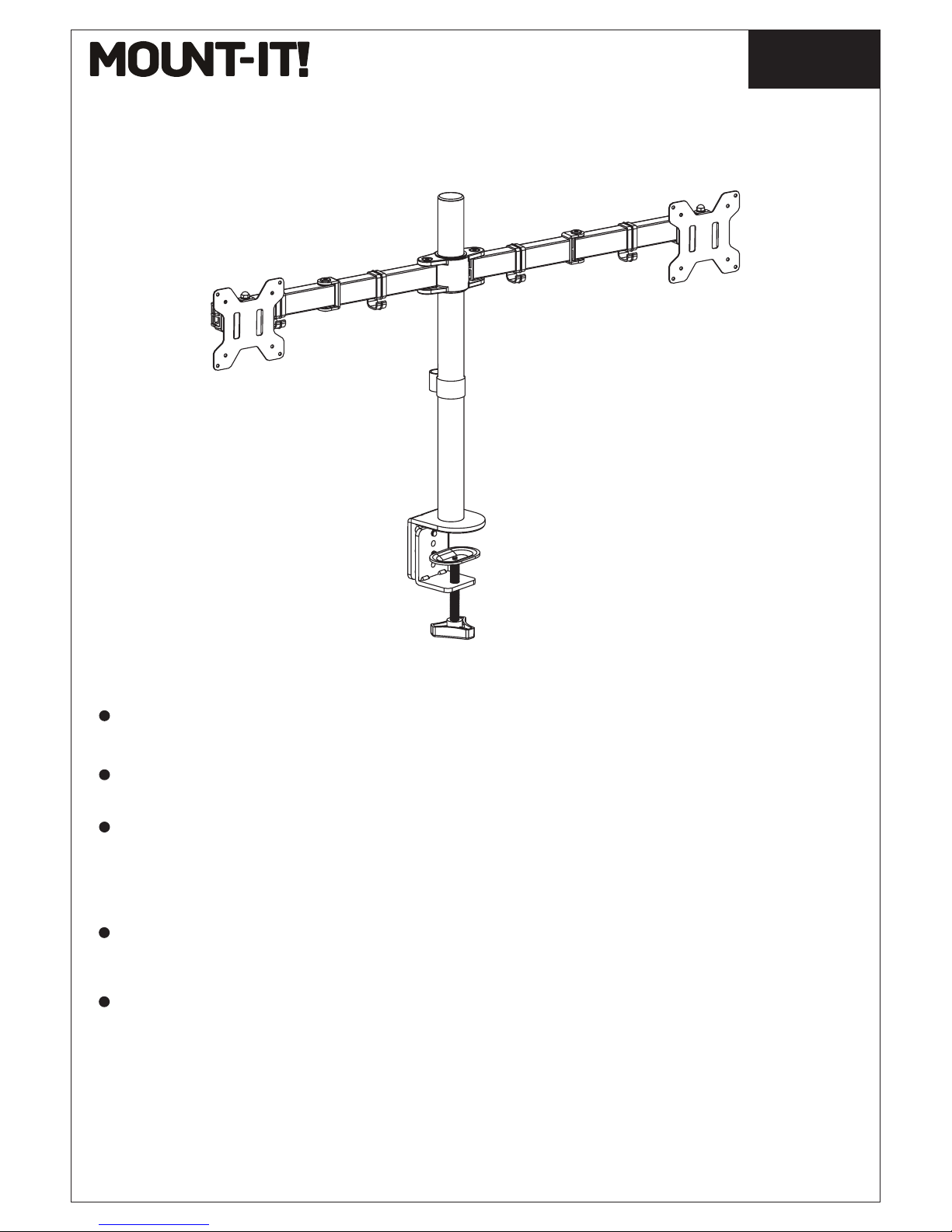
MI-2752
1
Installation Instruction
UNPACKING INSTRUCTIONS
IMPORTANT SAFETY INFORMATION
Carefully open the carton, remove contents and lay out on cardboard or other protective
surface to avoid damage.
Check package contents against the Supplied Parts List in the next page to assure that all
components were received undamaged. Do not use damaged or defective parts.
Carefully read all instructions before attempting installation.
Install and operate this device with care. Please read this instruction before installation, and
carefully follow all instructions contained herein. Use proper safety equipment during installation.
Please call a qualied installation contractor for help if you don't understand these directions or
have any doubts about the safety of the installation.
Do not use this product for any purpose or in any conguration not explicitly specied in this
instruction. We hereby disclaims any and all liability for injury or damage arising from incorrect
assembly, incorrect mounting, or incorrect use of this product.
Page 2
2
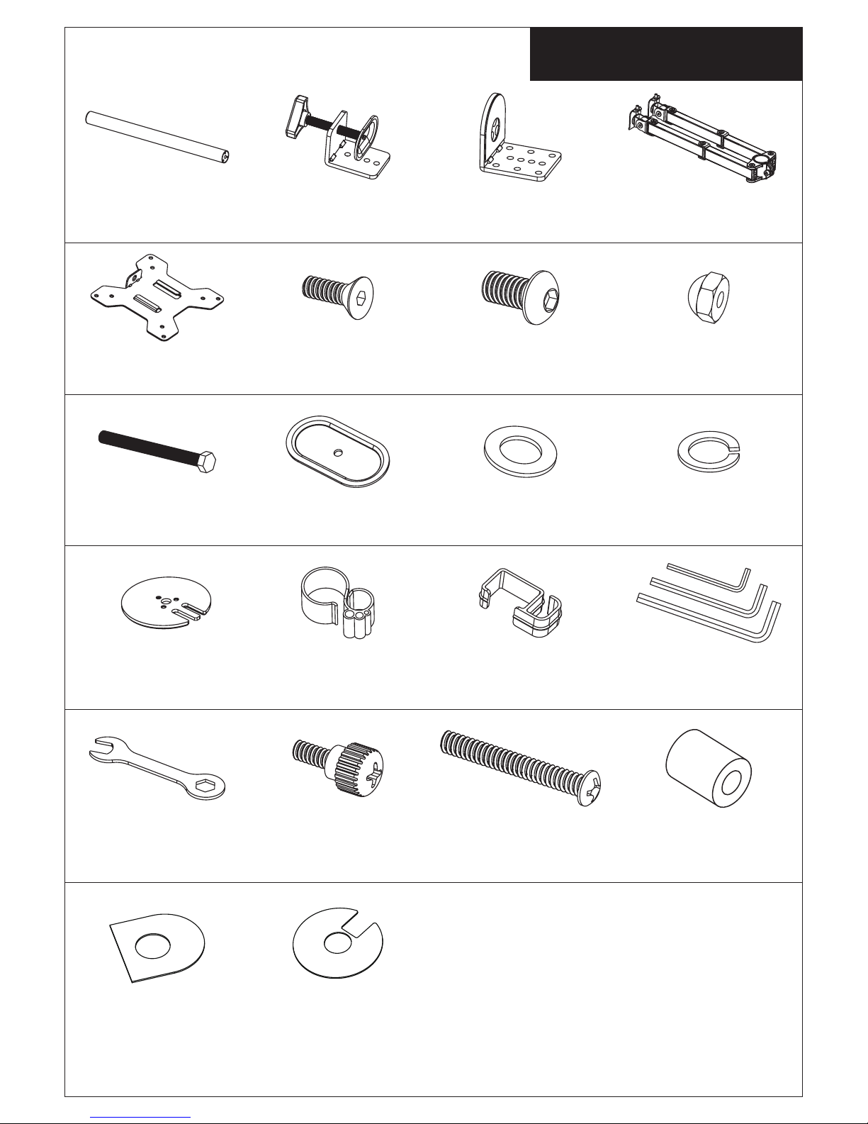
Supplied Parts List
(1)Soft Pad-t1
(1)Pole-a (1)“C” Clamp-b (1)“C” Clamp Brace-c (1)Swivel Arm-d
(2)VESA Plate-e (3)M5x14 Bolt-f (2)M8x12 Bolt-g (2)Nut-h
22
(1)M10 Bolt-i (1)Support Plate-j (1)M10 Washer-k (1)Spring Washer-l
(1)Grommet Base
Plate-m
(1)Wire Clip-n1 (4)Wire Clip-n2 (1)Allen Key-o
(1)Wrench-p (8)M4x12
Thumb Bolt-q
(8)M4x30 Bolt-r (8)M4 Spacer-s
(1)Soft Pad-t2
Page 3
3
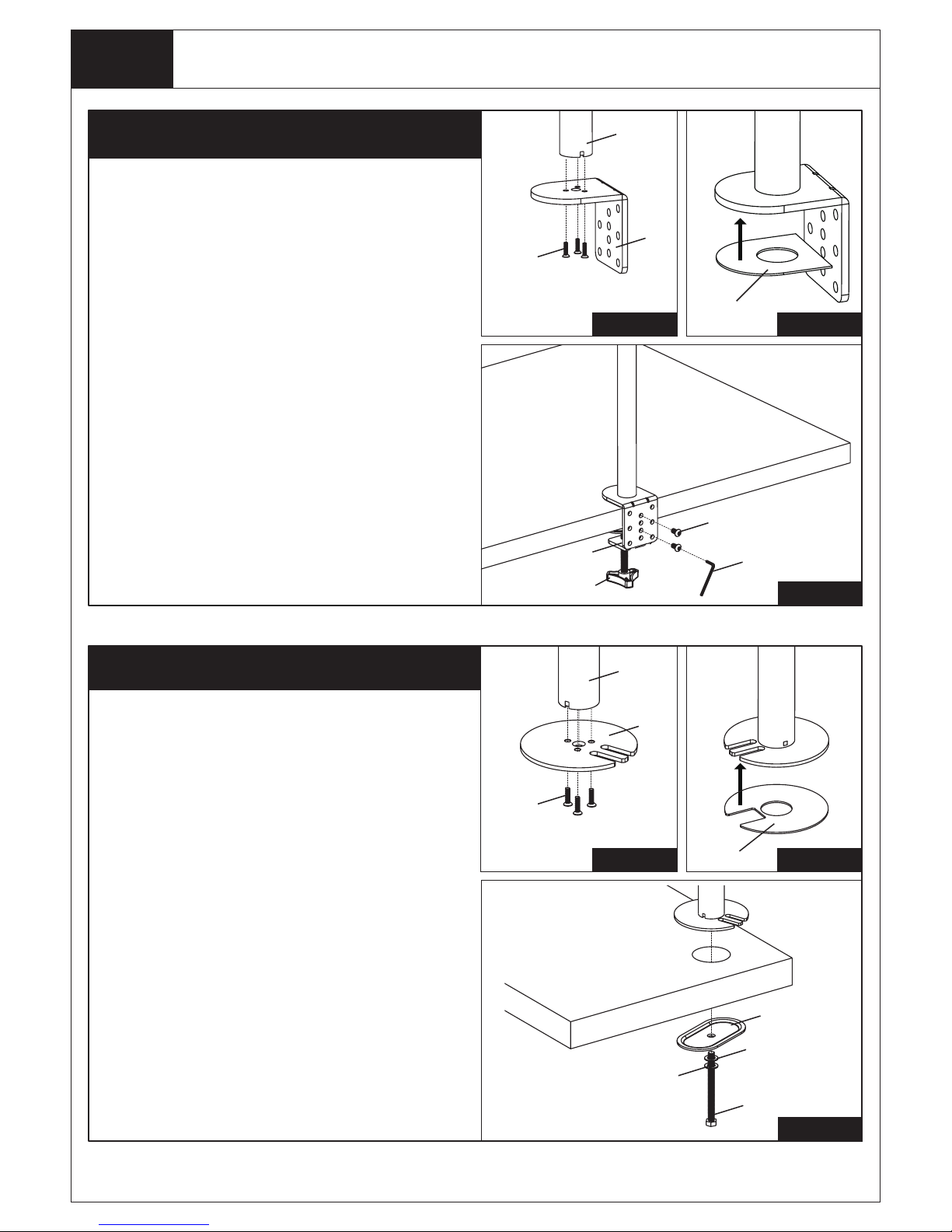
Step 1
Install the Pole to the Desktop
1.Install the “C” Clamp Brace(c) to the
Pole (a) using 3pcs M5x14 Bolts(f), and
tighten using the Allen Key(o),see
Figure 1.
2. Attach Soft Pad(t1) to the “C” Clamp
Brace(c), see Figure 2.
3. Install the “C” Clamp(b) to the pole
assembly according to the thickness of
the desktop. The thickness can be
changed to three positions. Connect it
using 2pcs M8x12 Bolts(g), and tighten
using the Allen Key(o). Tighten the “C” Clamp to the desktop using the plastic
knob, see Figure 3.
g
o
b
Plastic Knob
t1
Figure 2
a
c
f
Figure 1
Figure 3
Option A: Desk Clamp Install
j
i
k
l
a
m
f
Figure 4
Figure 6
Option B: Grommet Base Install
t2
Figure 5
If the existing grommet hole comes with a
plastic protector, remove it to ensure a flat
surface before installing the desk mount.
1.Install the Grommet Base Plate(m) to the
Pole(a) using 3pcs M5x14 Bolts(f), and tighten using the Allen Key(o), see Figure 4.
2. Attach Soft Pad(t2) to the Grommet Base
Plate(m), see Figure 5.
3. Position the Pole(a) on the mounting
surface and secure using the Support Plate
(j), M10 Washer(k), Spring Washer(l) and
M10 Bolt(i). Fasten the M10 Bolt using
provided Wrench(p), see Figure 6.
Existing Grommet Hole Installation
Page 4
Install the Pole to the Desktop
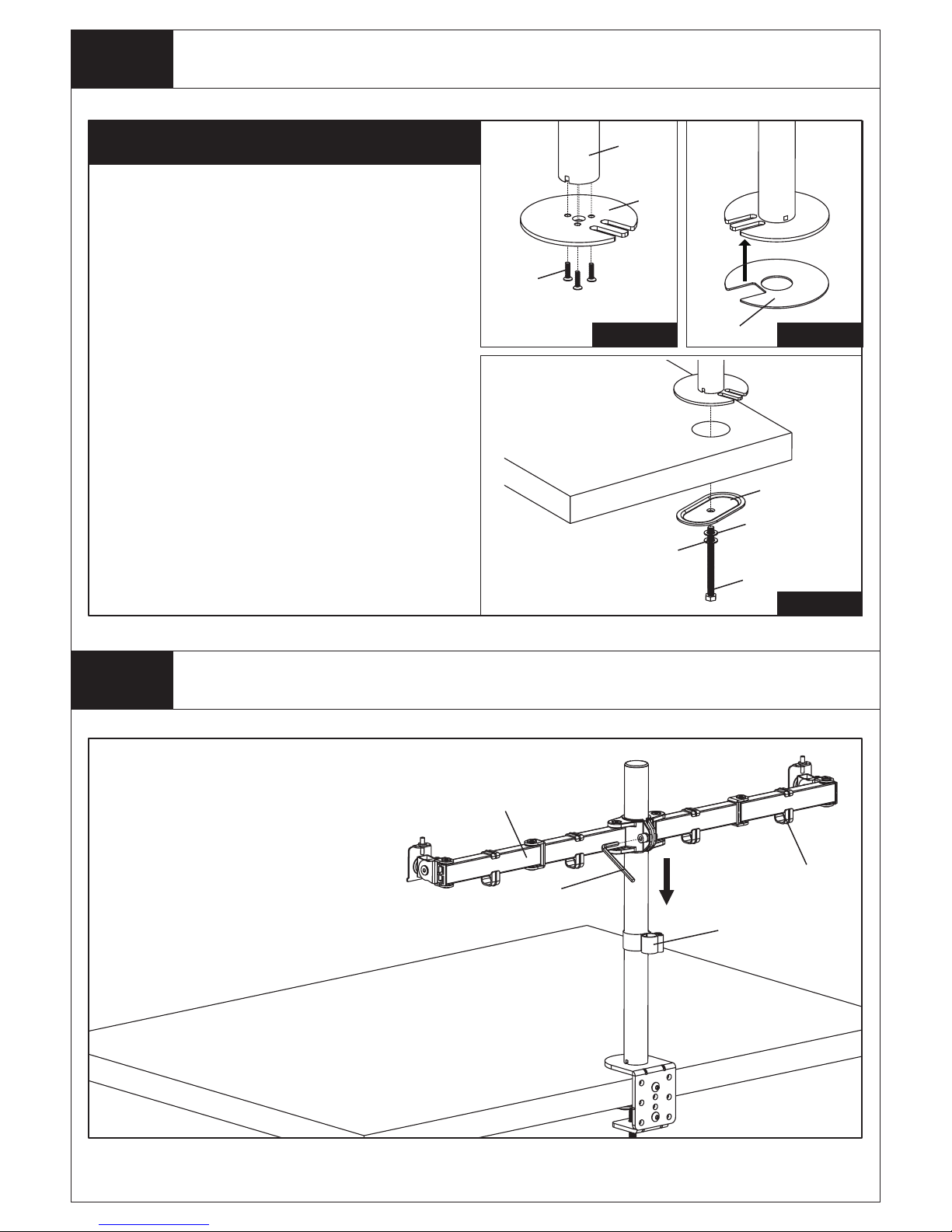
Install Arm to the Pole
Install Swivel Arm(d) to the
Pole(a). Fasten the bolt with supplied Allen Key(o). Attach the
Wire Clip(n1,n2) to the Pole(a)
and Swivel Arm(d).
j
i
k
l
a
m
f
Figure 7
Figure 9
Option C: Grommet Base Install
t2
Figure 8
1.Position the Pole(a) on the mounting
surface and mark the center hole. Drill a 3/8"
(10mm) diameter hole at the marked position through the mounting surface.
2. Install the Grommet Base Plate(m) to the
Pole(a) using 3pcs M5x14 Bolts(f), and tighten using the Allen Key(o), see Figure 7.
3. Attach Soft Pad(t2) to the Grommet Base
Plate(m), see Figure 8.
4. Position the Pole(a) on the mounting
surface and secure using the Support Plate
(j), M10 Washer(k), Spring Washer(l) and
M10 Bolt(i). Fasten the M10 Bolt using
provided Wrench(p), see Figure 9.
Self Drilled Grommet Hole Installation
4
Step 1
Step 2
d
o
n1
n2
Page 5
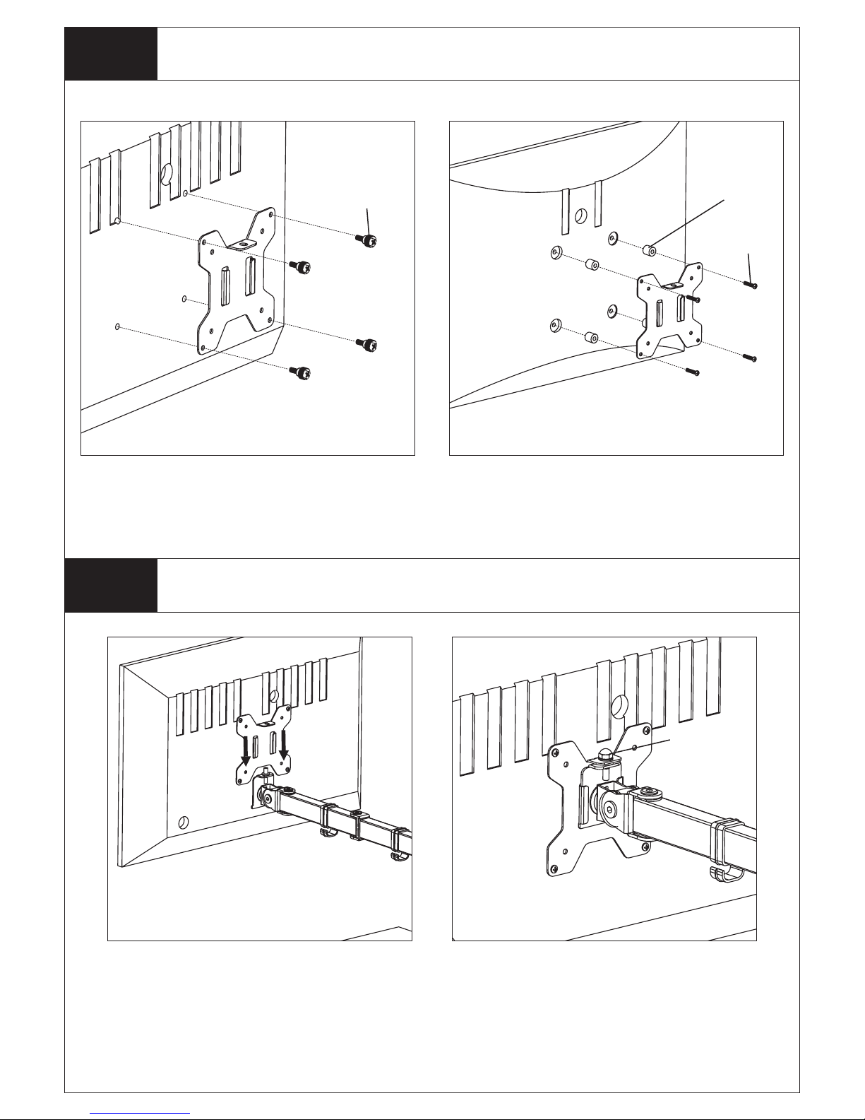
Attach the VESA Plate to the Monitor
5
s
r
h
q
Step 3
Slide the Monitor onto the Head of Swivel Arm
Step 4
For Monitor with Flat Back For Monitor with Curved or
Recessed Back
Slide the monitor onto the head of
Swivel Arm(d) as shown in the above
diagram.
Install the security Nut(h). Make sure the
security nut is installed before you rotate
the monitor.
Page 6
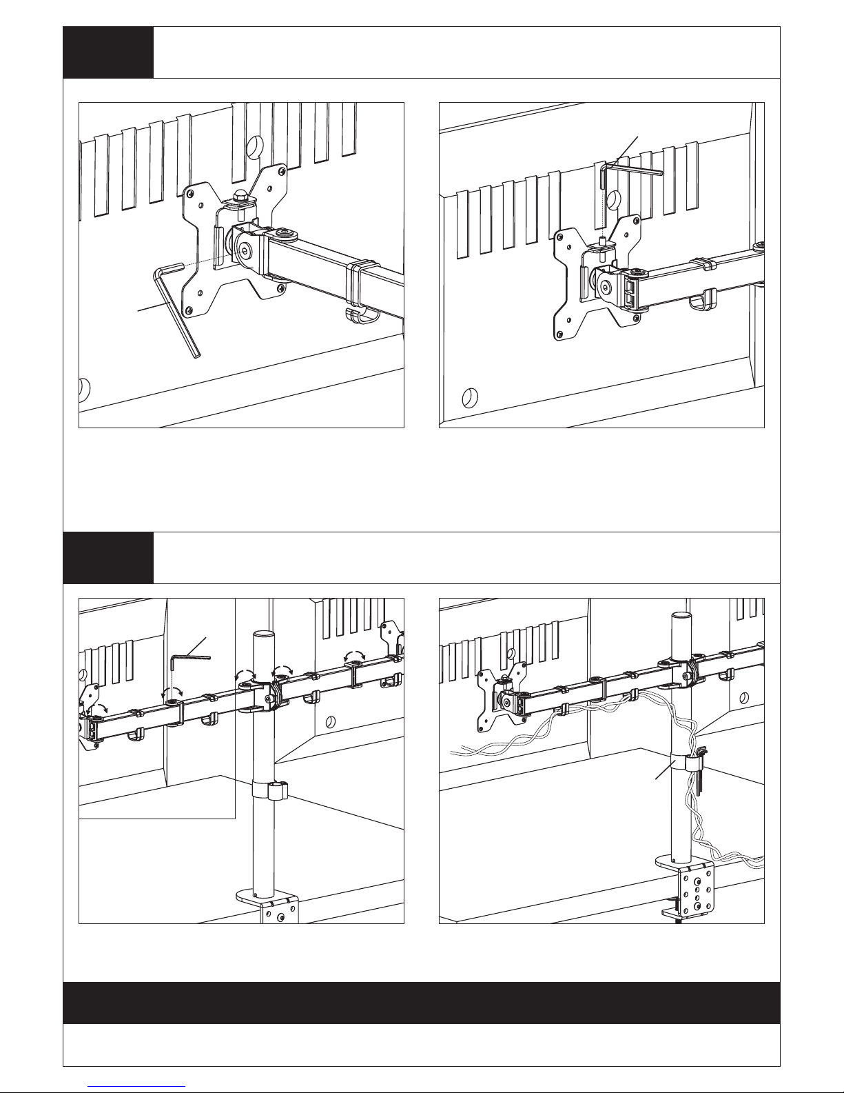
Tighten the bolt with the supplied Allen
Key(o) to fix the tilt angle.
Use the supplied Allen Key(o) to make the
necessary adjustments.
Manage the wires and store the Allen
keys(o) in Wire Clip(n1) for future use.
If one monitor is lower, remove the Nut(h)
and turn the bolt counter-clockwise with
supplied Allen key(o) to raise the monitor.
Install the Nut(h) after the adjustment.
6
o
Make the Necessary Adjustments
Step 5
Manage the Wires and Store the Allen Keys on Wire Clip
Step 6
Fix the tilt angle
Ignore this step if
monitors are level
Thank you for choosing our products!
o
o
n1
 Loading...