

Page 1
LCD/LED/Plasma
Wall Mount Manual
Page 2

Pro duct Ov er view:
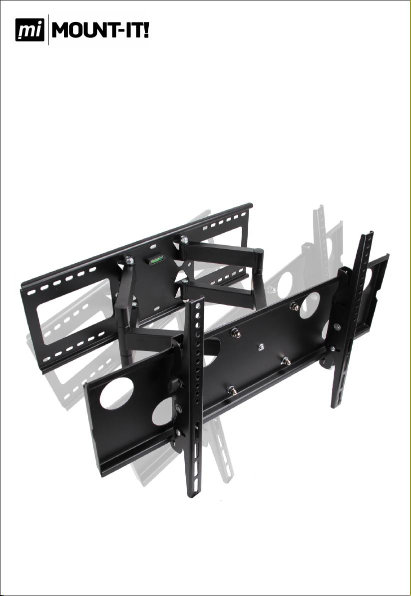
The articulat in g arm mount features a a t pro l e of 3.4" from the wal l to the bac k of your
disp la y and a fu ll exte ns io n o f 19.1" f rom t he wa ll as w ell a s +/- 15 degr ee s of ti lt. The mount is
cons tr uc te d w it h 23. 3L BS of 10 0% High Grade Stee l p ro vi di ng a stu rd y and reli ab le mo un t.
The moun t's sol id wall pla te allo ws for quic k and easy ins ta ll ation and will support a wi de
vari et y of st ud app li ca ti on s u p to 24 " a pa rt . The moun t wil l t th e m aj or it y o f LCD, LE D a nd
Plas ma Disp la ys up to 6 5” . M os t LCD a nd Plas ma display s 65 ” and smal le r confo rm s to th e
VESA St an da rd s. Ho we ve r, this mo un t wi ll supp or t mo st od d si ze d hole pa tt er ns that d o not
conf or m to t he V ES A Standard s.
Key Fe ature s:
Cove rs H ol e Pa tt erns 26.9 " Ho ri zo nt al by 15.75 " Ver ti ca l an d Up to VESA 600 x4 00 mm
Exte nd s to 1 9. 1" a nd Collap se s To Less Than 3.4 " Fr om The Wa ll
15° Up & D ow n Til t
Buil t- in B ub bl e Level
Doub le S tu d In st allatio n
Inst al la ti on H ardware I nc lu de d
2
Page 3
A B
C
D E
F
G
H
I
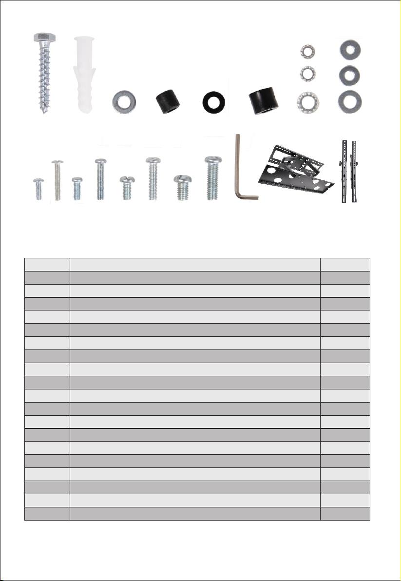
Part
A
B
C
D
E
F
G
H
I
J
K
L
M
N
O
P
Q
R
S
J
K L M N
O
P
Descript ion
8x50mm Lag B olt s
S10x50mm C onc ret e Anchors
8mm Washer
8x15mm Pla sti c Spa cer
M8 Plastic S pac ers
6x13 Plast ic Sp ace r
M5/M6/M8 mm Lo ck Wash er
M5/M6/M8 Washer
M4 12mm Scre w
M4 25mm Scre w
M5 12mm Scre w
M5 25mm Scre w
M6 12mm Scre w
M6 25mm Scre w
M8 12mm Scre w
M8 25mm Scre w
M6 Allen Wre nch
Mount
Left Arm, Rig ht Arm
Q
R
S
Quantity
6
6
6
4
4
4
4/4/4
4/4/4
4
4
4
4
4
4
4
4
1
1
2
3
Page 4
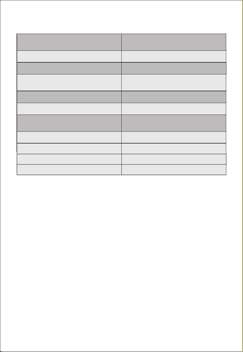
*Hol e Pa tt er n Co verage/ Su pp or te d VESA Patte rn s:
Up To 26. 9" Horizo nt al b y 15 .7 5"
Verti ca l or V ES A 600 x400mm
Unit Weight:
Ship pi ng D im en sions:
Unit M at er ia ls :
Til t Ra ng e:
Total Ro ta ti on :
Arm Ex te ns io n/ Collaps ed :
Wal l Pl at e Dimension s:
TV Pla te D im en si ons:
TV Arm Br ac ke t He ig ht:
Cabl e Ma na ge me nt Openin g: Two Squa re h ol es
Net: 2 3. 3L BS G ro ss: 25.7L BS
29.9 "X 9. 1" X3 .7"
Arms , Wal l Pl ate and TV Plate:
100% H ig h Gr ad e St eel
±15°
130°
Full y Ex te nd ed : 19.1"
Full y Co ll ap se d: 3.4"
25.6 x8 .7 "
28.7 x8 .3 "
16.4 "
3.9" X6 .9 "
4
Page 5
Installaon instruc on:
Note : Pl ea se r ea d all insta ll at io n in structi on s ca re fu lly befor e in st al lation.
For st an da rd w oo d stud inst al la ti on p lease sta rt a t Se ct io n 1: Woo d Stud Inst al la ti on .
For Co nc re te /M ortar ins ta ll at io ns please r ef er t o Se ct ion 2: Conc re te /M as onry Inst al la ti on.
Secon 1: Wood Stud Installaon:
1. Loc at in g a St ud : First you w il l ne ed t o lo cate the st ud i n th e wa ll y ou wish to mo un t yo ur T V
to. If you k no w ho w to loca te your s tu d pl ea se contin ue t o St ep 2. I f yo u do n ot k no w ho w to
loca te y ou r st ud p lease con ti nu e.
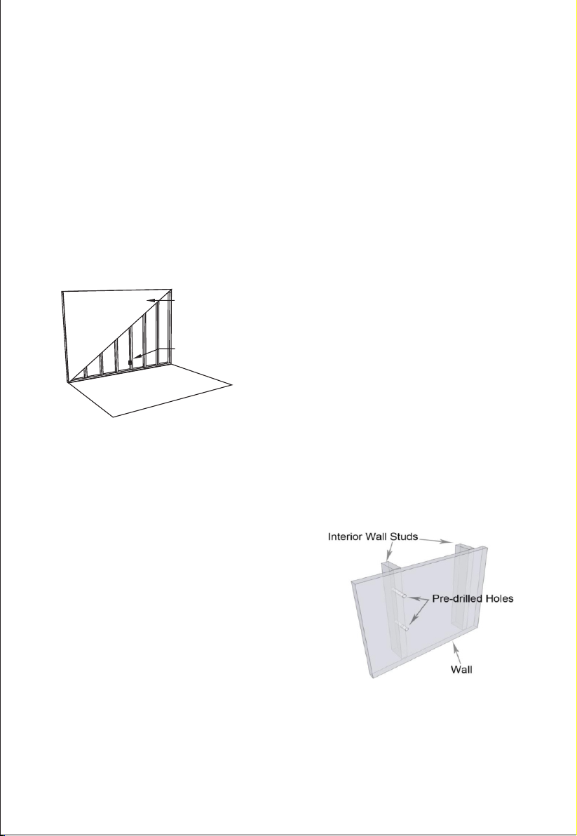
Findin g a Wooden Stud in Your Home: O ne q ui ck w ay t o n d a wa ll s tu d is t o n d a po we r
outl et on th e w al l. Wall outl et s a re no rm al ly located ne xt to a s tu d. Th e e as ie st wa y t o c on rm
the lo ca ti on o f a st ud is with an ele ct ro ni c stud nde r, wh ic h yo u ca n purchas e at a ny
hard wa re s to re .
2x4 Stud Wall
(16-24" Spacing)
Outlet located
next to stud
usin g a th in na il an d h am mer. With the ham me r, p ou nd th e t hin nail into th e w al l i n t he ar ea of
the st ud . If the nail is t o th e side of t he stud it w il l go throug h th e drywall a nd easi ly into the
empt y sp ace i n the w al l. If t he nail i s on th e stu d, o nce i t goes th ro ugh t he drywal l, i t w il l not g o
into t he wa ll ea si ly as it i s h it ti ng th e woo d of th e s tu d. Ke ep re pe at in g t hi s pro ce ss in t he ar ea
of th e st ud u nt il y ou c an tell exactl y wher e the s tud st arts a nd e nd s. The middle of th ese tw o
poin ts i s th e ce nt er of the stu d.
2. Mark and Pre- Drill Inst al lation Points: Once
yo u ha v e l o cat e d yo u r s t uds , Ma r k t h e h o l e
loca ti on s whe re you intend to dr il l, as su re th at
they a re leve l wi th on e an other. U se a 5m m dr ill b it
to p re-dril l fou r holes to a de pt h o f 2 ”. If you do no t
have a metri c drill bit a 3/16 ” drill bit wil l work as
well .
Once yo u n d an in itial st ud , ot he r wa ll studs ar e
typi ca ll y l oc at ed in th e w al l e ve ry 16 ”. Pl ease note in
some hom es the y are cons tr uc ted with s tu ds eve ry
24". A dd it io nally, man y walls have “no n- st an da rd”
stud s l oc at ed next to d oo rs , w in dows and r ep la ce s.
To get the be st supp or t for y ou r mou nt , it is import an t
that you put the m ou nt in g sc re ws f or your wall plat e
into t he c en te r of th e wa ll s tu d. If it is d if c ult to
dete rm in e t he ex ac t c en te r o f t he st ud wi th yo ur st ud
nde r, yo u can g et the ex ac t loc at io n of th e stud
5
Page 6
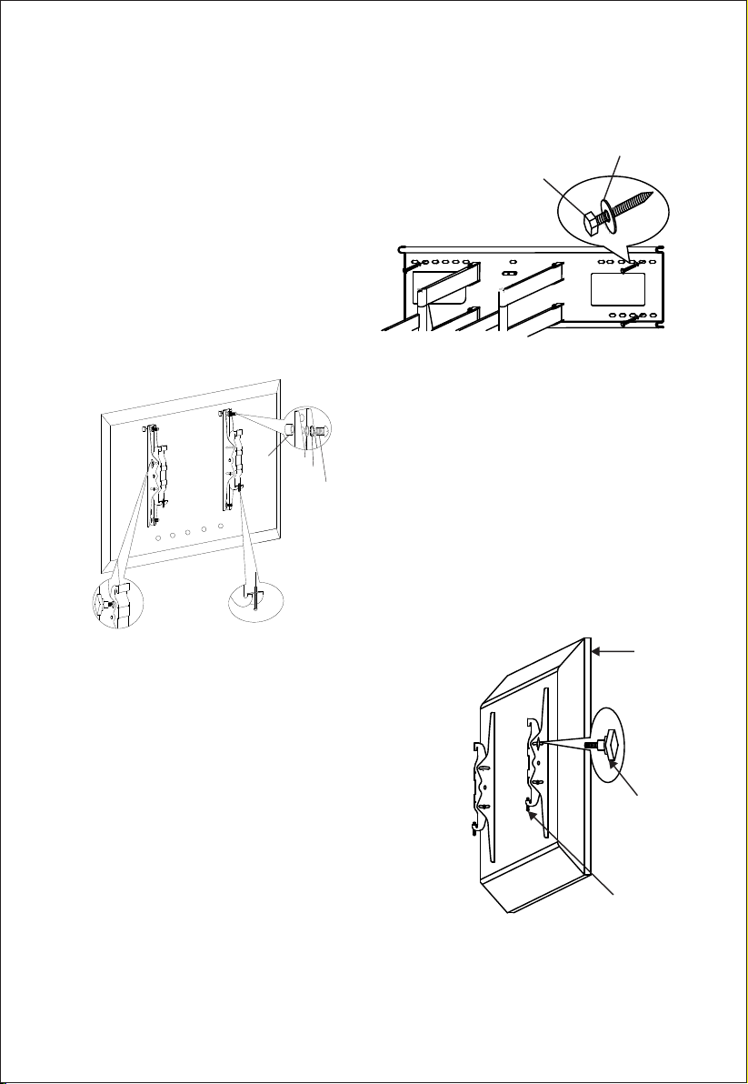
3. At ta ch in g The Mount t o You r Wall :
Once the fo ur holes are pre -d ri ll ed , af x the
wall plat e to the wall with all four lag bolts and
wash er s i nt o t he wa ll . The in cl ud ed pl as ti c
anch or s DO NOT need to be us ed fo r woo d
stud i ns ta ll at ion.
Note on loca ti ng hardware to moun t arms
to y ou r display : If your d is pl ay do es n ot
come wi th t he mountin g s crews in the ba ck o f
the di sp la y, ch ec k th e or ig inal desk s ta nd a s in
some case s t he sa me sc re ws to ho ld th e d esk
stan d are used al so to mou nt your displ ay. If
neit he r of these opt io ns wor k, th e hardwa re
pa ck i n c l u d ed w i t h you r m o u nt c o n t a i ns
seve ra l of t he m os t co mm on sized sc re ws f or
moun ti ng y ou r ar m bracket s to y ou r di sp lay.
D/ E/ F
H
G
I/J /K/L/ M/N/O /P
Part C
Part A
4. Ins ta lling Arm Bra ck ets Ont o The Back
of Y o u r D i sp l a y : O n c e yo u lo c a t e t h e
appro pr iate s c r e w s , a t t a c h th e tw o ar m
brac ke ts to the ba ck of the dis pl ay. To at ta ch
the arms use the prope r bolt and loc k wa sh er
for ea ch o f the f ou r mountin g ho le s. In t he
even t your display has re ce ssed holes or a
curv ed b ac k, your h ar dw ar e pack in cl ud es
plas ti c s pa ce rs to ll the gaps. T he se pla st ic
s p a c er s a re n o t n e c es s a r y f o r m o s t
inst al la ti on s.
5. Att ach in g Yo ur Di spl ay to Th e Wa ll Pl ate : Af te r
inst al li ng the wa ll plate an d testing t o ensure th at it i s
atta ch ed secure ly and atta ch ing the arms to the back of
the di splay, i t is ti me to a tt ach y ou r dis pl ay to t he wa ll . Th is
step ma y r eq uire t wo pe op le, atta ch th e hook to th e t op lip
of th e w al l p la te. Once th e h oo ks are secu re ly se t o nto the
wall plate you ca n no w le t the b ottom of t he dis pl ay r ot at e
back a nd i t wi ll s im ply hang on t he m ou nt .
6. Se cu ri ng Your Display : The all mount ut il izes a set
scre w a ttached to the bo ttom o f each on e of th e ar m
brac ke ts . To se cu re th e a rm br ac ke t t o the T V p la te , l oc at e
the set scre w on t he bottom of the arm then tigh te n in a
cloc kw is e mo tion un ti l ti ght. This s cr ew ensu re s that yo ur
disp la y wi ll n ot l ift off of t he mount.
6
TV
Tilt Knob
Safety Screw
Page 7
7. Ad ju st in g Your Ti lt : To a dj us t th e tilt positi on o n yo ur disp la y yo u will need to lo os en t he
knob o n t he side o f e ac h one o f the a rm br ac ke ts, s et the de sired t il t a nd then t ig hten th e a rm s
back u p. You can lo os en the sc rews sl ig ht ly so t ha t it will s ti ll hold whil e yo u ad just yo ur t il t,
once y ou h av e se t th e desired a ng le o f ti lt y ou can then f ul ly t ig ht en the knob s.
Sect ion 2: Co ncr ete and M asonr y Insta lla ti on:
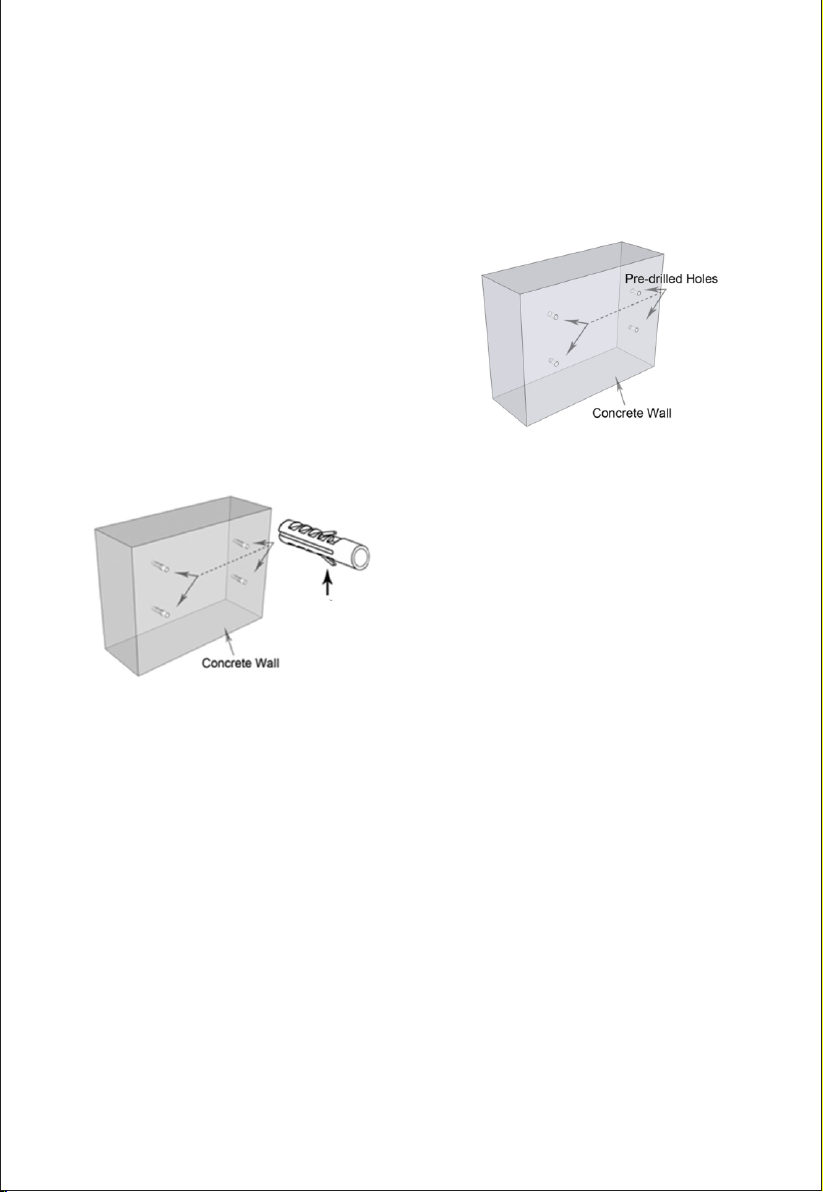
1. M a r k I nsta l l a t i on P o i n t s: O n c e you h a v e
sele ct ed th e locat io n y ou want the mount to b e,
mark the ex act l oc at io n w he re the ancho rs and lag
bolt s will be install ed . N ex t, pr e- dr il l t he ho le s u si ng
a mason ry 10 mm dr ill bit t o a de pt h o f 2 ” then in se rt
the supplie d ancho rs . If you do not have a metr ic
dril l bi t a 3/ 8" d ri ll bit will w or k.
Dril li ng Into C on cr ete: W he n drilli ng into c on cr ete
or ma so nr y, y ou h av e t o use a special ma so nry dr il l
bit which you c an pur ch as e a t you r loc al hardwar e
stor e, u sing a stand ar d drill b it wi ll n ot pe ne tr ate t he
conc re te and it will just dul l you r dri ll bit. It is not
reco mm en de d t o drill a nd mo un t i nt o concr et e blo ck
or mo rt ar jo int s. If mo un tin g i nto conc re te or
maso nr y we re co mm en d usin g all of the sup pl ie d
plas ti c anch or s and lag b ol ts f or m ax im um s up po rt .
The sup pl ie d p la stic anc ho rs ar e r ated for us e u p t o
165L BS , b ut if y ou pre fe r you can g o to yo ur loc al
ha r dwa r e st ore and p urc h ase m eta l co n cre t e
B
anch or s.
2. At ta ch in g The Mount t o You r Wall :
Once the h ol es ar e p re -d rilled a nd al l p la st ic
anch or s are inser te d, af fi x the wal l pla te with the
four s up pl ie d la g bolts int o th e wa ll .
At this point you can proceed back to Step 4 in the wood stud
installa tio n sec tion to comple te yo ur Co ncrete/Masonr y ins tallation.
ATTE NTION:
This m ou nt must be i ns ta lled us in g th e supplie d ha rd wa re with a ll lag bo lt s screw ed i nt o your
stud . I f y ou are moun ti ng in to concr et e o r m ortar, al l f ou r a nchors a nd sc re ws must b e u se d for
maxi mu m su pp or t.
Rev ision d ate: 07/09 /2016
7
 Loading...