

Page 1
En glish
Installation Instruction
UNPACKING INSTRUCTIONS
! Carefully open the carton, remove contents and lay out on cardboard or other
protective s urface to avoid damage.
! Check package c ontents again st the Suppli ed Pa rts List in t he next page to assure
that al l com ponents we re receive d und amage d. Do not use damaged or de fective
parts.
! Care fully read all inst ructi ons before attemp ting installation.
IMPORTANT SAFETY INFORMATION
! Install a nd operate this device with c are. Please read this inst ruction befo re
installati on, and carefully follow all instruc tions contained herein . Use proper safety
equipment du ring in stallation.
! Pl ease call a qualifie d ins tallation contract or for help if you don't understand thes e
directions o r have an y doubts about the sa fety of the install ation .
Do not use this produc t for any p urpose or in any configuration not expli citly specifie d
in this in struction. We hereby discla ims any and all liabi lity for inju ry or da mage
arising from i ncorrect assembly, incorre ct moun ting, or incorrec t use of this product.
1
Page 2
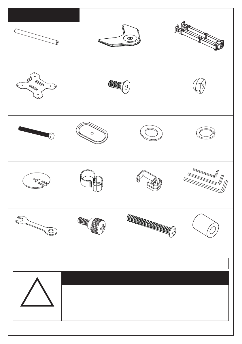
Su pp li ed Par ts List
(1) Pole-a (1) Swivel Arm-c(1) Weighted Base-b
(2) VESA Plate- d (2) Nut-h
(1)Support P late-j(1)M10 Bolt- i (1)M10 Was her-k (1)Spring Washer-l
(1) Grommet Ba se
Plate-m
(1)Wrench-p
(1)Wire Clip -n1 (1)Allen Key -o
(3) M5x14 Bolt -e
Tools Required
(4)Wire Clip -n2
(8)M4 Spacer -s(8)M4x12 Bol t-q (8)M4x30 Bol t-r
Phillips Screwdriver
!
WARNING
CAUTION!
The monitor de sktop mount must be e venly posit ioned on a
stable ho rizontal sur face. If the mount is not po sitioned in a
balanced man ner, it may fal l, resulting in possible inju ry
and/or damag e. The optional des ktop bolt may be used to
provide addi tional stabilit y.
2
Page 3
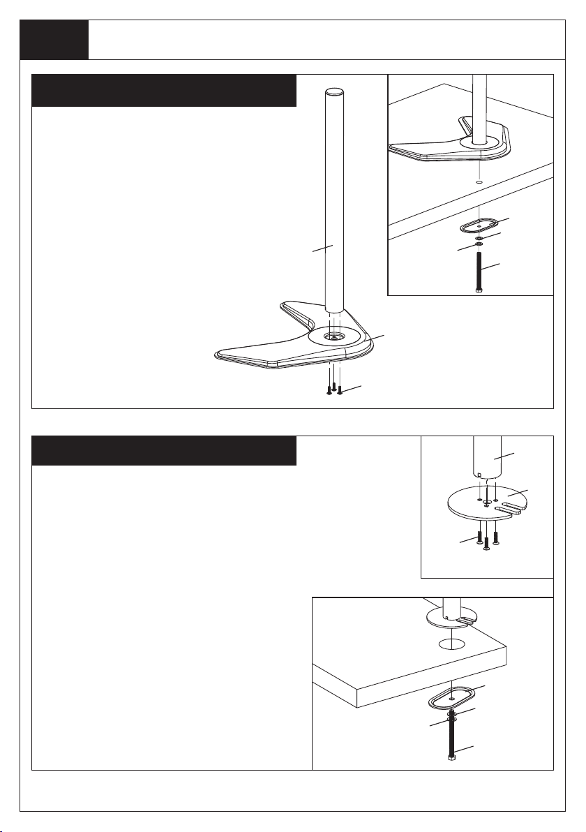
St ep 1
Install the Pole to the Desktop
Option A: Weighted Base Install
1. Install the Po le (a ) to th e Weight ed
Base( b) us ing 3pcs M5x14 Bolts(e ), an d
tight en using the Allen K ey(o), see F igure 1.
2. Optional ly, you can drill a 10mm diameter
hole i n your desk an d secure u sing the
Suppo rt Plate ( j), M10 Washer(k ), Spring
Was her(l) an d M1 0 Bolt(i) . Fa sten the M10
Bolt wi th provided Wrench (p), see Figure 2 .
Figure 1
j
k
a
l
l
Figure 2
i
b
e
Option B: Grommet Base Install
Existing Grommet Hole Insta llation
If the existing grommet hole come s with a
plast ic pro tector, remov e it to ensure a flat
surfa ce before insta lling the de sk mount.
1. Install the Gro mmet Bas e Plate( m) to the
Pole( a) u sing 3p cs M 5x14 Bolts(e), and
tight en using the Allen K ey(o), see F igure 3.
2. Posi tion t he Po le(a) on the m ounting
surfa ce an d secure using the Sup port Plate
(j), M10 Washer(k ), Sprin g Wa sher(l) and
M10 Bo lt(i). Faste n th e M10 Bolt using
provi ded Wrench(p), see F igure 4.
3
Figure 4
a
m
e
Figure 3
j
k
l
i
Page 4
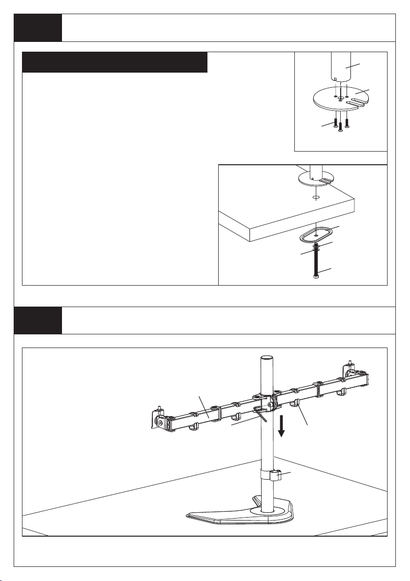
St ep 1
Install the Pole to the Desktop
Option B: Grommet Base Install
Self Drilled Gromme t Hole In stall ation
1. Posi tion t he Po le(a) on the m ounting
surfa ce a nd mark the cen ter hol e. D rill a 3 /8"
(10mm ) diameter hole at the ma rked posit ion
throu gh the mounting s urface.
2. Install the Gro mmet Bas e Plate( m) to the
Pole( a) u sing 3p cs M 5x14 Bolts(e), and
tight en using the Allen K ey(o), see F igure 5.
3. Posi tion t he Po le(a) on the m ounting
surfa ce an d secure using the Sup port Plate
(j), M10 Washer(k ), Sprin g Wa sher(l) and
M10 Bo lt(i). Faste n th e M10 Bolt using
provi ded Wrench(p), see F igure 6.
St ep 2
Install Arm to the Pole
Figure 6
a
m
e
Figure 5
j
k
l
i
Install Swiv el A rm(c) to the
Pole(a). F asten t he bolt w ith
supplied Al len Key(o). At tach
th e Wire Cl ip(n1,n2) to t he
Pole(a) and Sw ivel Arm (c).
c
o
n2
n1
4
Page 5
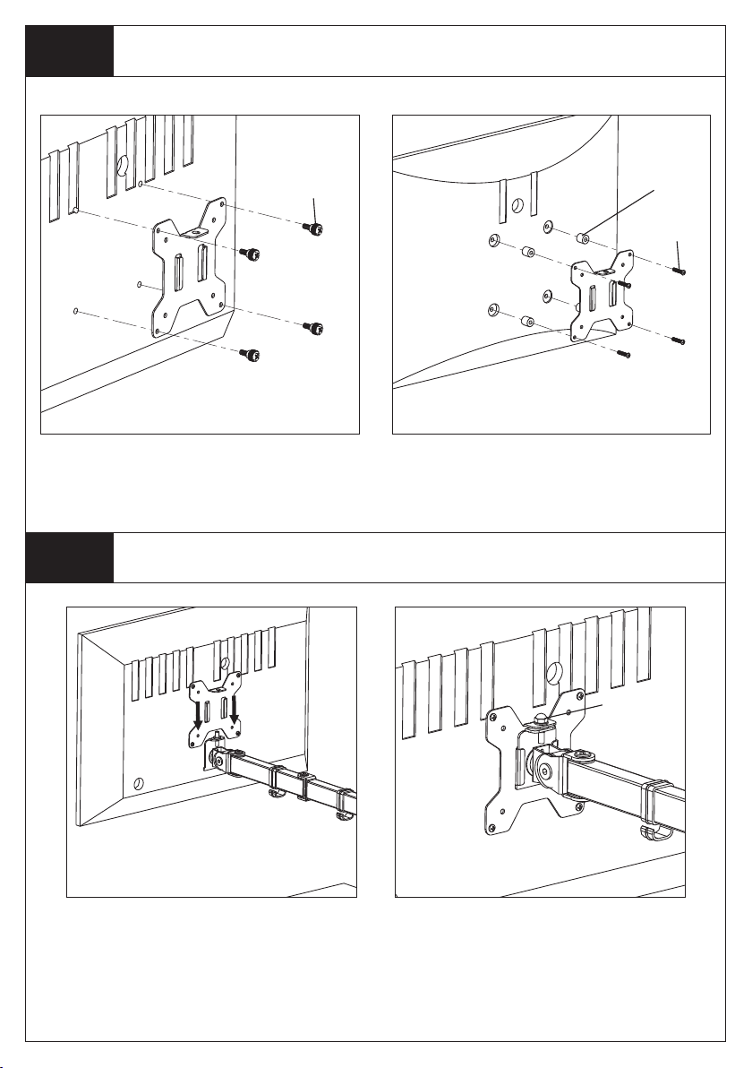
St ep 3
Attach the VESA Plate to the Monitor
For Monitor with Flat Back
St ep 4
Slide the Monitor onto the Head of Swivel Arm
q
s
r
For Monitor with Curved or
Recessed Back
Slide the monito r onto the head of
Swivel Arm(c) as shown in the
above diagra m.
h
Install th e se curit y Nut(h). Make
sure th e security nut is installed
before you rot ate the monitor.
5
Page 6
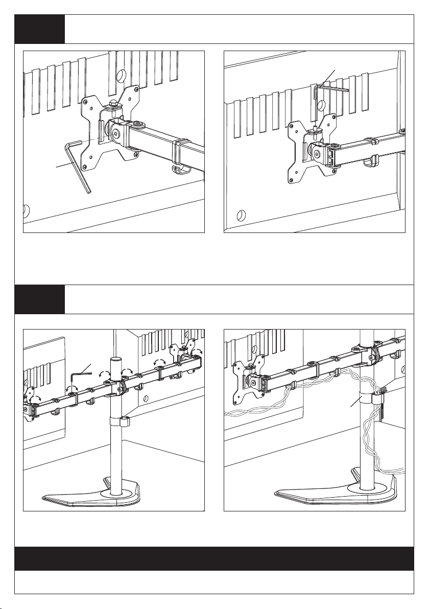
St ep 5
Fix the Tilt Angle and Adjust the Level of Monitor
o
Fix the tilt angle
Tight en the bolt with the supplie d Allen
Ke y(o) to fix t he tilt ang le.
o
Ignor e this st ep if
monitors are level
If one m onitor is l owe r, remov e the Nut(h) and
turn the bolt counter-clockwise with supplied
Allen ke y(o ) to raise the mo nit or. Install the
Nut(h) aft er th e adj ust ment.
St ep 6
Make the Necessary Adjustments and Manage the Wires
o
Use the su pplied Al len Key( o) to make
the necessar y adjus tments.
Thank you for choosing our products!
n1
Manage the w ires a nd store th e Allen
keys(o) in Wir e Clip( n1) for future use.
6
 Loading...