

Page 1
MOUNTAIN OFF ROAD ENTERPRISES. LLC.
P.O. BOX 690
DELTA COLORADO 81416
970-625-0500
E-mail: [email protected]
www.mountainoffroad.com
INSTALLATION INSTRUCTIONS FOR SR104
PLEASE READ AND UNDERSTAND TERMS/POLICIES BEFORE YOU INSTALL THIS SYSTEM
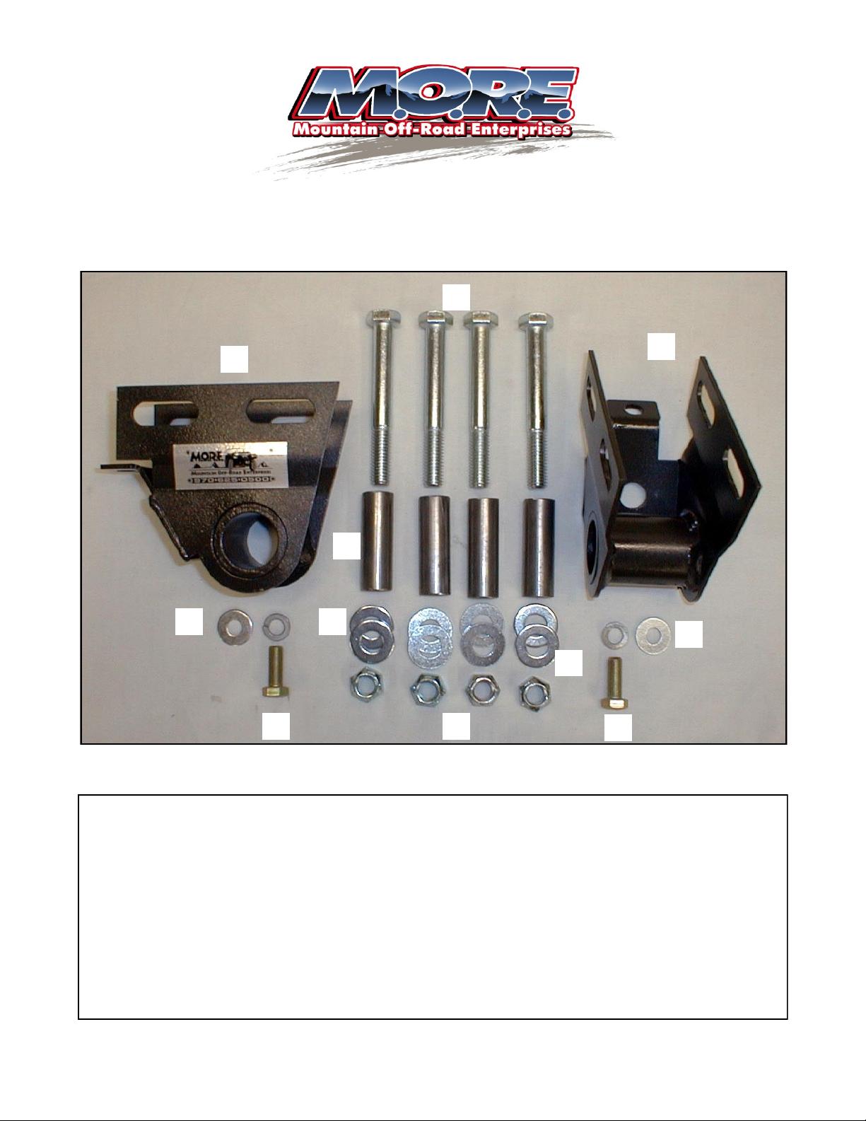
M.O.R.E. Shackle Hanger System # SR104 contains the following items:
ITEM DESCRIPTION QUANTITY PART NUMBER
A Bracket-Shackle Hanger 2 SR104
B Bolt-Shackle Hanger 3/8”x1” 2 18834
C Washers-Lock & Flat 3/8” 2 33008/33622
D Tube Spacer 3/4”x2-3/8” 4 S101399
E Bolt-Shackle Hanger to Frame 1/2”x4” 4 13219
F Nut-Crimp Lock 1/2” 4 37268
G Washer-Flat 1/2” 8 33086
- Instruction Sheet 1 SR104 IS
Photo of items on page 2 of these instructions. Please familiarize yourself with all components in the system.
These instructions will refer to items by letter, not description. Read all instructions carefully before work is
started on your vehicle. In addition to basic hand tools, the following specialty tools are needed to perform this
installation: Angle head drill (electric or air), 3/4” diameter drill bit, 1/2” diameter drill bit, 21/64” drill bit, 3/8-24
(fine thread) tap, floor jack, jack stands (4), torque wrench, grinder and or cutting torch.
FIT and TOLERANCES: All parts in this system are the results of countless hours of research, testing, fitting
and refining. Jeep® frames have a wide tolerance on bolt hole centers from frame to frame. This is why
M.O.R.E.™ has installed several “slots” in which to mount our bracketry. In addition to the factory tolerances,
most people install other then factory equipment such as bumpers, winch mounts, springs etc. M.O.R.E.™ has
done the best job we can to insure that our parts fit with the different possibilities. However, you may find it necessary to grind, elongate, bend, or force the parts in this system to fit on your rig. Please use common sense
when installing these parts, and understand that if you modify them in any way, they are not returnable!!
SR104 PAGE 1 of 6
Page 2
SR104 Contents
E
C
A
B
G
D
F
A
C
H
B
Notes:
SR104 PAGE 2 of 6
Page 3

STEP BY STEP INSTALLATION INSTRUCTIONS:
STEP 1: Remove the spring pivot hangers from the frame rails (behind the axle). This can be done with a
hand grinder and cut-off wheel, torch or saw-zall. SEE FIGURES 1A, 1B, & 1C. Be very careful and do not cut into
the frame. Just grind the welds. A chisel and hammer comes in handy for knocking loose the brackets. After the
stock brackets are removed from the frame, grind the welds flush and paint the bare frame with some black paint.
STEP 2: Find items “A” and install the bushings and sleeves that you removed from the stock shackle hang-
ers. SEE FIGURE 2. With a mallet, tap items “A” on the frame where you just removed the stock spring pivot hang-
ers. The tab on the under side (for the locking bolt item “B”) faces forward. Depending on your springs you may be
able to now set the shackle angle at 60 degrees with the springs hanging ( No Weight ) and everything will be fine,
See Figure 3 . We suggest that you do this as a starting point but once the hanger has been clamped to the frame
at the 60 degree angle you then apply weight to the springs. The shackle angle should be straight up and down 90
degrees with the weight on the springs, see figure 4 , If it is not 90 degrees than move the bracket “A” forward or
back until the correct angle is achieved.
STEP 3: Find the exact center of the slotted holes, and punch a mark. SEE FIGURE 5 & 6. This must be
done as accurately as possible, in the inside and outside of the frame rails, drivers and passenger side. Center
punch the lower “lock mounting bolt” hole at this time as well. SEE FIGURE 7. Remove items “A” from the frame.
With a 1/8” drill bit in a angle head drill, bore a pilot hole through the center punched marks, all locations. SEE FIG-
URES 8 & 9. Now, with a 1/2” bit in a power drill, enlarge the pilot holes ON THE SIDES OF THE FRAME ONLY to
1/2”. Do not drill the underside lock mounting bolt holes at this time!!! Drill from the outside toward the inside using
the inside pilot hole to keep the bit lined up. Enlarge the OUTSIDE HOLES ONLY to 3/4”. SEE FIGURE 10.
Chamfer any burrs that maybe present.
STEP 4: Now, enlarge the underside “lock mounting bolt” holes to 21/64”. Tap these drilled holes with a 3/8”
x 24 (fine thread) tap. Use cutting oil and tap slowly and carefully. Make sure the tap is straight and true when going
up through the hole. SEE FIGURE 11
STEP 5: Insert items “D” into the 3/4” holes you just drilled. SEE FIGURE 12. Be care full not to drop them
into the boxed frame! They should press in with a slight amount of pressure.
STEP 6: Re-install items “A” on the frame over items “D”. Grab all four items “E” and install one item “G”
over each, and install “E” through item “A” and “D”. Then in the inside of the frame install another item “G” over the
threads of item “E” and one item “F” on each. Re-check the shackle angle, and if correct, tighten items “E” & “F” to
55 Lb. Ft. torque.
STEP 7: Install items “C” over items “B” and thread items “B” into the tapped holes. Tighten them to 10 Lb.
Ft. torque. Reinstall the leaf springs. Switch the springs from end to end (the large eye or pivot end now installs up
front in the S.R.S.™ bracket). Install your shackles to your springs and to items “A”. SEE FIGURE 13. Use
thread locking compound on the threads or, new locking nuts on your bolts. Do not tighten at this time. Remove
the jack stands. Jump up and down several times on the front bumper to “seat” the springs. Tighten your stock
shackle bolts to 10 Lb. Ft. torque.
STEP 8: Test drive the Jeep® . Chances are the steering wheel may not be centered. You can adjust the
drag link to center it. Installing this shackle reversal system will not affect the alignment (camber or toe-in), so having the Jeep® aligned is not necessary. The caster will increase slightly, however it is a non -tire wearing angle.
Go back and check all of your work and make sure everything is done properly. Check the brake lines and make
sure that they are not being stretched to far.
SR104 PAGE 3 of 6
Page 4

STEP 9: Your drive shaft will need to have a long travel slip yoke installed to work properly with this system.
Call Tom Wood’s Custom Drive Shafts at: 877-497-4238. DO NOT TRY TO SHORT CUT THIS STEP OR DAMAGE COULD OCCUR TO YOUR DRIVE TRAIN!!!
You are finished! Be sure to re-check all hardware for tightness after 100 miles. If you have any questions, please
call. Thank you for purchasing this product from M.O.R.E.™ Keep on Jeepin’.
Figure 1A
Figure 1B
Figure 1C
SR104 PAGE 4 of 6
Figure 3 Figure 2
Page 5

Figure 4
Inside Frame Rail Drivers Side-Forward
Figure 5
Figure 6
Figure 8
Figure 7
Figure 9
SR104 PAGE 5 of 6
Page 6
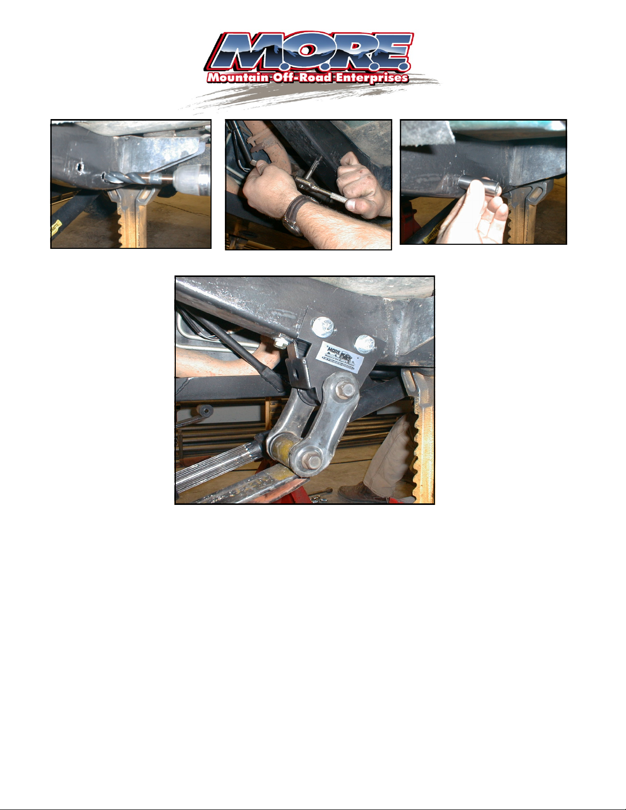
Figure 11 Figure 10
Figure 13
Figure 12
TERMS-POLICIES:
RETURNS: No returns will be accepted without prior permission from M.O.R.E.™ LLC. After you receive a Return Goods Authorization (RGA) number, mer-
chandise must be returned prepaid and insured. A claim must be made with in 30 days from receipt of merchandise. The original invoice or a copy with the
RGA number written on must accompany all returns. A 20% restocking fee will be charged on all parts returned for credit or refund unless merchandise is
proven to be defective or was shipped wrong by M.O.R.E.™ LLC. No merchandise will be issued credit or refund if it has been installed, modified, used in any
way or is in unsalable condition.
WARRANTY: All merchandise is warranted to be free from defects in materials and workmanship prior to installation. Any alteration or im proper use will void
this warranty. Because all parts we sell are intended for use in heavy-duty applications it is not possible to warrantee or guarantee the performance of any
items. M.O.R.E.™ LLC. products and the products manufactured by others, which we sell may be subject to an infin ite variety of conditions due to the
manner in which they are used, serviced and/or installed. Purchasers and users of such products rely upon their own judgment as to the suitable use selection,
service and installation of such products.
PRODUCT DISCLAIMER: Modification of your vehicle to enhance performance with parts sold by M.O.R.E.™ LLC. may create a dangerous condition which
could cause serious bodily injury, and the buyer hereby expressly assumes all risks associated with any such modifications. A ll parts sold by M.O.R.E.™ LLC.
are for racing or off road use only. Mountain Off Road Enterprises LLC. will not accept responsibility for personal injury or property damage arising from the
failure of any parts manufactured or sold by M.O.R.E.™ LLC.
Specifications are subject to change without notice.
Jeep® , JK® , Wrangler® , are registered trademarks of DaimlerChrysler .
M.0.R.E.™ is a trademark used by Mountain Off Road Enterprises, LLC. The M.O.R.E.™ logo and these instructions are copyright© , 2008.
SR104 PAGE 6 of 6
 Loading...