

Mountain Off Road BLCJ7679 User Manual
MOUNTAIN OFF ROAD ENTERPRISES, LLC.
P.O. BOX 690, DELTA, COLORADO 81416
970-625-0500 970-625-3747 Fax
E-mail: info@mountainoffroad.com
www.mountainoffroad.com
INSTRUCTIONS for M.O.R.E.™ BLCJ7679 1” BODY LIFT KIT
Thank you for purchasing this M.O.R.E.™ Body Lift Kit/System. It is designed to fit 1976-1979 Jeep™ CJ-5,
CJ-7 vehicles with manual or automatic transmissions. It will work with or with out a suspension lift kit. Read
all instructions before starting the installation. Please call if you have any questions.
CONTENTS:
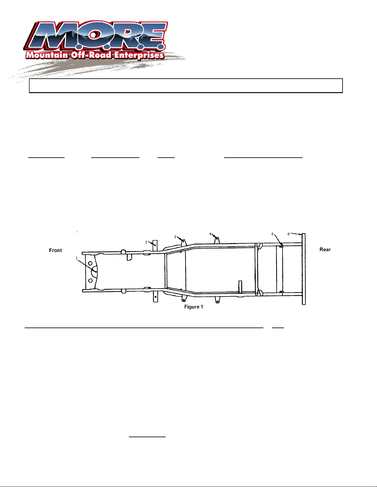
QUANTITY: DESCRIPTION: SIZE: LOCATION: (see figure 1)
11 Aluminum Puck 2-1/4" x I" All.
10 Hex Head Bolt 3/8" x 3-1/2" 2,3,4,5,6.
1 Hex Head Bolt 7/16" x 3-1/2" 1.
4* Hex Head Bolt 3/8" x 4" 2,6. *
10 Washer-Flat 3/8" 2,3,4,5,6.
1 Washer-Flat 7/16" 1.
* Locations 2 and 6 may use 3/8" x 4" bolts. Check the length of your stock body bolts to determine which
replacement bolts are to be used for your application.
There are 4 steps to be addressed when installing this body lift kit on your Jeep™ CJ:
1: The steering shaft and/or column.
2: The radiator/fan shroud.
3: The clutch linkage (or automatic transmission shift linkage).
4: Installing the one inch 0 pucks and longer bolts.
STEP 1: The steering shaft and/or column. Since the body is going to be raised from the frame by one inch
and the column is attached to the body, the shaft that connects the column to the steering box will have to
gain length by approx. 3/8". There are two ways to make this happen:
1A: The shaft is telescoping from the factory (so it can collapse in case of a collision). To make it gain length
or extend the two halves must have the plastic locking device removed. The plastic must be melted out by
heating the shafts. If you choose this method (A), remove the entire shaft from the Jeep™ . Use a torch and
slightly heat the two halves until the plastic is melted out and the two shafts will slide apart. Do this in a well
ventilated area cause the meeting plastic stinks! Clean them with a wire brush, and paint them. Do not reinstall the steering shaft at this time. See figure 2.
BLCJ7679
PAGE 1 of 4

1B: The steering column has a slight amount of adjustment from the factory. It may or may not have enough, only
you can be the judge of this. The adjustment is located where the column bolts to the under dash bracket, and the
firewall. Loosen the two bolts (do not remove) that attach the column to the bracket. They are located directly
above the brake pedal. Loosen the bolts that clamp the column to the firewall bracket and the bolts that attach the
bracket to the firewall (do not remove). The steering column should now be loose enough to push or pull it approx.
1/2" in or out of the firewall. Leave the bolts loose at this time. Which ever method you choose, A or B, do not
short-cut this step! The steering system will not function properly with out this adjustment.
STEP 2: The radiator/fan shroud. If you do not have a shroud omit step 2. If you run an electric fan omit step 2. In
order to keep the engine driven fan spinning in the center of the shroud, the radiator and shroud will need to be
lowered one inch on the grill. Some radiators have several mounting holes or slots which will work for this purpose.
Most will have to have new holes drilled one inch lower then the holes used when installed at the factory. Only the
radiator needs to be drilled, not the shroud. Remove the 4 mounting bolts that hold the radiator/shroud to the grill.
Separate the shroud from the radiator. Simply center punch a mark one inch below the existing holes in the radiator mounting flange and drill 4 new holes. Do not re-attach the radiator/shroud at this time.
STEP 3: The clutch linkage A, or automatic transmission shift linkage B. If your Jeep™ has a hydraulic clutch
then omit step 3.
3A: It is possible that the clutch linkage will need to be modified. The bracket that bolts the bellcrank to the firewall
may need to be lowered by one inch, and the rod that connects the clutch pedal to the bellcrank may need to be
lengthened by one inch. The bellcrank pivots on bushings that allow for some misalignment and we have found
that the one inch body lift usually doesn’t cause any problems. However, if you feel as though the linkage needs
attention you can perform the above steps to re-align the bellcrank.
3B: Automatic transmission shift linkage. (Jeep™ CJ-7 with factory TH400 and Quadra-Trac). The shift rod from
the column to the transmission has a pinch bolt that needs to be loosened. Also, remove the shift linkage rod between the Quadra-Trac low range and the floor. Go to the next step leaving all of the above bolts loose!
STEP 4: Installing the one inch lift pucks. Loosen but do not remove all 11 body to frame mounting bolts. Hint, the
two hidden bolts are located behind the rear axle just in front of the fuel tank, location 5. Remove the one bolt under the grill, location 1. Remove 5 bolts on the drivers side of the body. Place a stout piece of wood on a floor jack
and raise the jack up to the floor pan between body mounts 3 and 4, toward the outside edge of the body. Raise
the body just enough to place the one inch pucks on top of the rubber insulators. NOTE: (If you are installing a
Body Lift System which includes new Polyurethane Body Mounts, install them at this time. The OEM steel
tube/washers that were removed from the rubber insulators are re-used. Also, when disassembling note the quantity and positions of any shims that may have been inserted for body alignment. These shims will have to be reused
to insure proper body alignment). It is recommended that you use a dab of thread locking compound on the new
longer bolts to keep them in place. Start the new longer bolts into the body but do not tighten them at this time.
Lower the floor jack and repeat this procedure on the passenger side of the body. Install the last puck in location 1
under the grill and start it's longer bolt. Re-torque all 11 bolts to factory specs. Now, it is time to re-install the steering shaft that you removed in step 1A. To keep the two halves from rattling, slightly coat the shafts with silicon before you assemble them.
PAGE 2 of 4
 Loading...