

Page 1
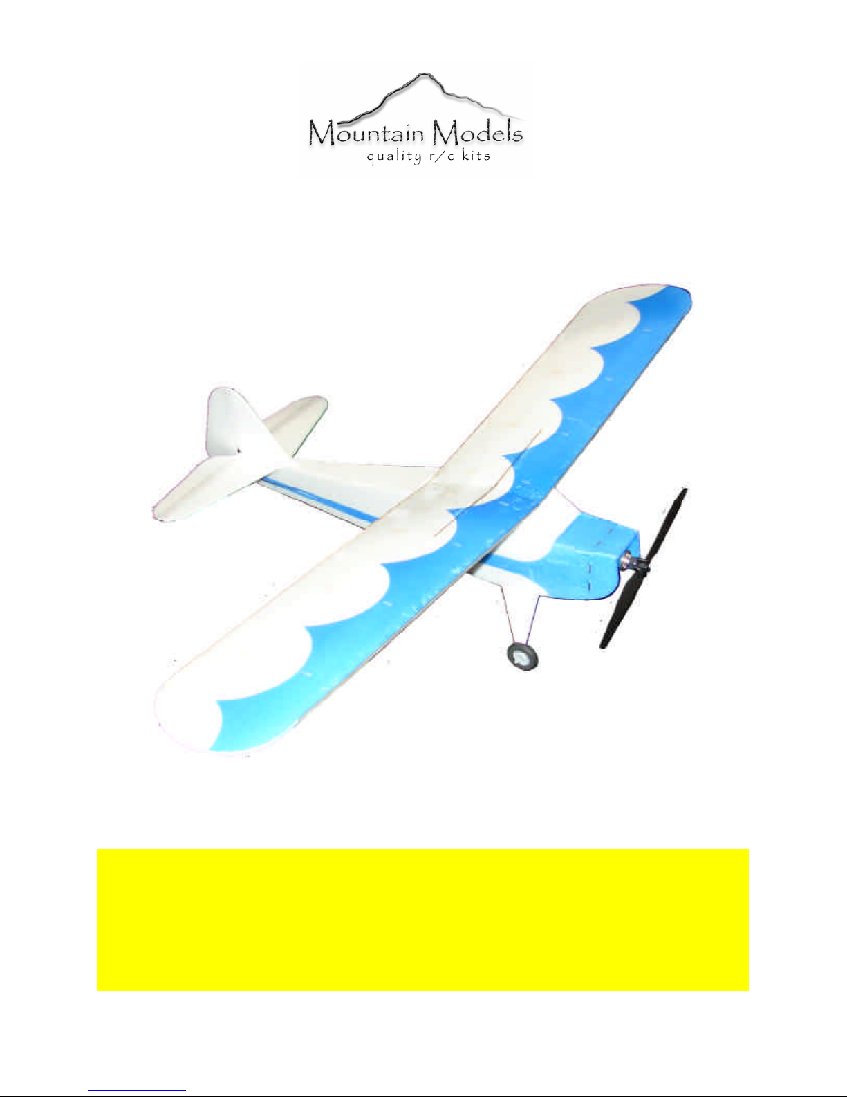
Taylorcraft
Indoor / Cul-De-Sac Flyer
Taylocraft Specifications
Wingspan: 28.0 in.
Wing Area: 117 sq. in.
Weight (Ready to Fly): 3.0 – 3.1 oz.
Wing Loading: 3.7 – 3.8 oz. / sq. ft.
LIABILITY RELEASE
In that Mountain Models has no control over the final assembly or material used for final assembly, no
liability shall be assumed or accepted for any damage resulting from the use by the user of the final userassembled product. By the act of using the user-assembled product, the user accepts all resulting liability.
If the buyer is not prepared to accept the liability associated with the use of this product, the buyer is
advised to return the kit immediately in new and unused condition.
THIS PRODUCT IS NOT INTENDED FOR CHILDREN 12 YEARS OF AGE OR YOUNGER
Warning: This product may contain chemicals known to the State of California to cause cancer or birth
defects or other reproductive harm
Page 2

Revision History
Date Revision Notes/Comments
04/07/2010 1.0 Initial Release
09/13/2010 1.1 Production Release
Thank you for purchasing the Mountain Models Taylorcraft. The Taylorcraft is a
super lightweight, easy to fly, but fun to toss around Depron plane. High quality
laser cut Depron and plywood parts make the assembly of this laser cut model
airplane kit a breeze!
We think you’ll find this plane to be a lot of fun, being able to be flown indoors and
small outdoor spaces. It handles some wind just fine, so you’ll be fine at a larger
field as well.
Thank you,
Brian Eberwein
Mountain Models
PO Box 9557
Colorado Springs, CO 80932
www.mountainmodels.com
Phone: 719.630.3186
2
Page 3

Parts List
Number in Kit
1 Set 3mm Depron Parts
4 1/64” Plywood LE & TE Reinforcements
1 1/16” Plywood Firewall
1 1/32” Plywood Sheet
1 1/32” Balsa Sheet
1 3/32” Balsa Sheet
2 0.032” x 12” Wire
1 0.045” x 12” Wire
Bagged Parts
2 Wheels
2 DuBro Wheel Keepers
1 1/64” Plywood Elevator Reinforcement
1 1/32” Plywood Tail Skid
4 Motor Mount Screws
Electronics You Will Need
• 1 ea. 10 gram, 2000 KV Outrunner
• 1 ea. GWS 6x3 HD Prop
• 2S-300 to 360 LiPo
• 1 ea. 6 Amp Brushless ESC
• 2 ea. 3.7 gram servos
• 1 ea. Lightweight (Berg4L, or similar) 4-channel RX
• 1 ea. 3 channel radio minimum
Description of Part
Building Materials You Will Need
• Smooth and flat work surface
• Wax paper or clear plastic wrap to protect the work surface
• Foam safe Cyanoacrylate (CA) glue and accelerator (or 5-minute epoxy, or white Gorilla Glue)
• Hobby knife with #11 blades
• Needle nose pliers
• Wire cutters
• Screwdrivers
• Sanding block, 320 grit sandpaper
3
Page 4
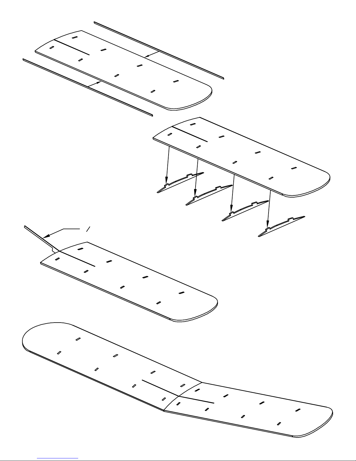
Step 2: Glue the 3/32" balsa ribs in
place on each wing, as shown. The
engraved lines on the wing go on the
bottom and help the wing bend to the
correct shape. Pile magazines on top
of the wing, while the glue is drying,
to make sure that the wing comes out
straight and properly curved to the
airfoil shape when the glue is dry.
Step 1: Glue the 1/64" plywood
leading and trailing edge
reinforcements in place on the wing,
as shown. Use a slower setting foam
safe CA or 10 minute epoxy
(sparingly). Make sure the wing is flat
and that the plywood is fully seated
against the foam.
1
" Plywood Wing Spar
32
Step 3: Glue the 1/32" plywood
wing joiner in place on the left wing
half, as shown. Make sure it is flush
with the top of the wing. When it is
dry, glue it to the other wing half. Use
some glue to fill in the gap on the
bottom of the wing where the two
halves come together.
Page 5
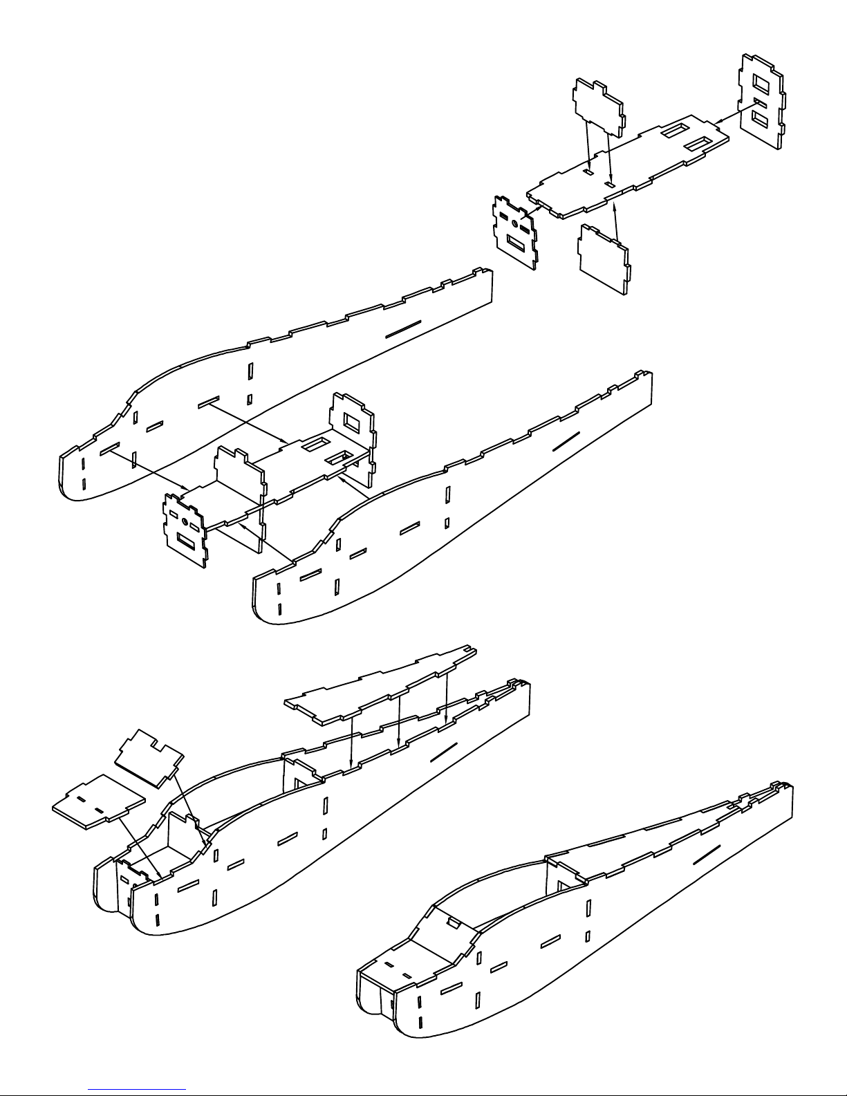
If you are using a slower setting glue, you
can assemble/glue up the entire fuselage at
once.
Step 4: Glue the formers in place
on the crutch, as shown in the image.
MAKE SURE that the plywood
firewall is glued so the engraved text
faces FORWARD.
Step 5: Glue on the fuselage sides,
as shown. Tape the rear end of the
fuselage together to help in alignment.
Step 6: Glue on the fuselage top
front, windshield, and rear fuselage
top, as shown.
Page 6
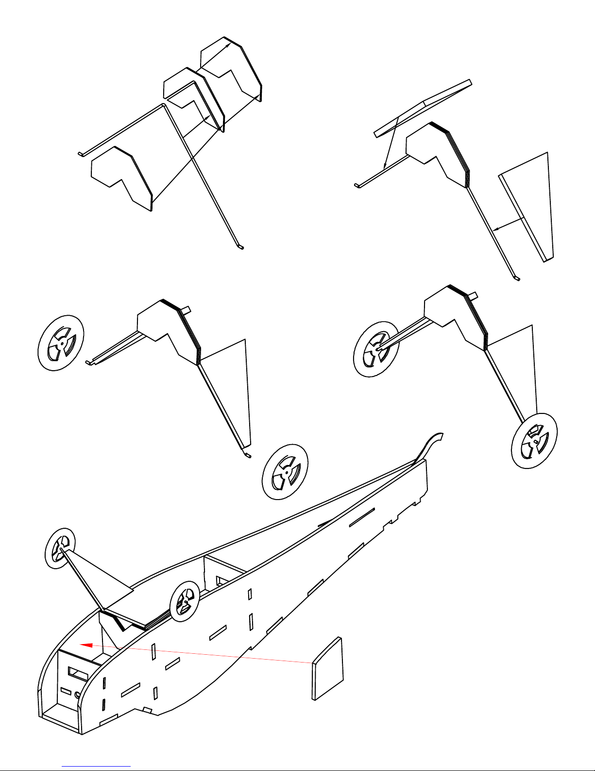
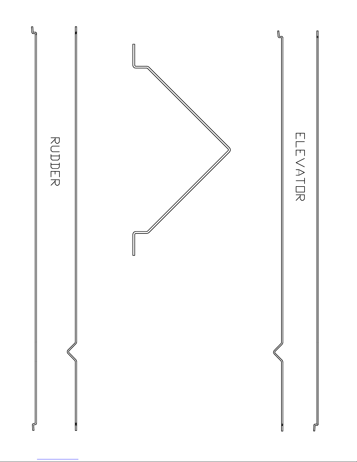
Step 7: Bend the
landing gear wires, as
shown in the wire drawing
sheet on the last page of this
manual.
Step 8: Glue the 1/32"
balsa landing gear mount
together, using thick CA,
with the landing gear wire
in between.
Step 9: Glue the landing
gear fairings onto the
landing gear wire. You can
groove the foam so the wire
sits in it slightly. This gives
a better glue joint.
Step 10: Place the
wheels onto the landing
gear wire and secure with
the shrink tubing.
Step 11: Glue the landing gear
assembly into the fuselage, as
shown, onto the front of the lower
former. The balsa landing gear
assembly should be flush with the
bottom of the former.
Step 12: Glue in the tail gear
skid against the inside of the
fuselage side. It should look like it
does in the side view on the next
page.
Step 13: Glue in the fuselage
fiewall doublers. They should be
glued to the inside of the fuselage,
pressed up against the firewall.
Page 7
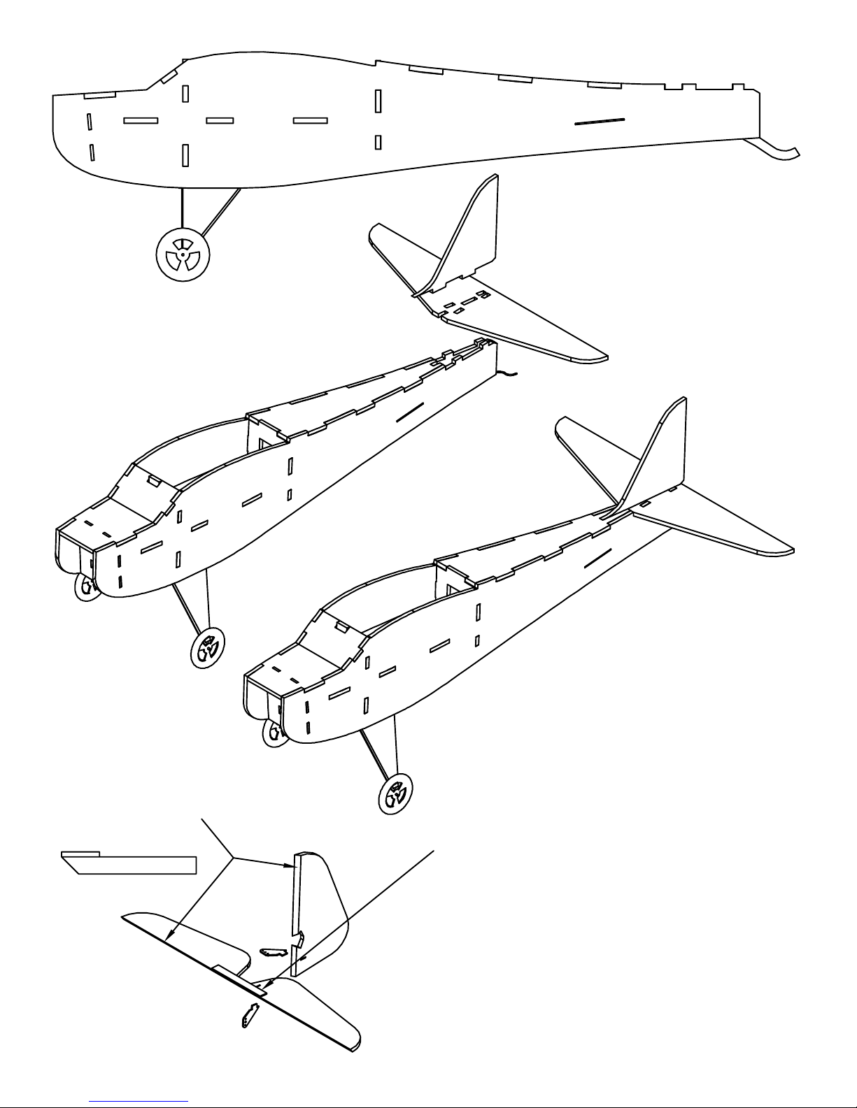
Step 14: Glue the stabilizer
and vertical fin in place, as shown.
MAKE SURE that the stabilizer is
horizontal and that the vertical fin
is at a 90 degree angle to the
stabilizer.
Step 15: Bevel the hinge side
of the rudder and stabilizer, as
shown. Use a sharp X-Acto and a
metal straight edge.
Step 16: Glue the 1/64" plywood
reinforcement onto the elevator as shown,
making sure the elevator is flat as the glue
dries. Take note as to where the control horn
hole is, in relation to what side the plywood is
glued onto.
Step 17: Glue the control
horns into the rudder and elevator,
as shown in the drawings. MAKE
SURE you glue them onto the
correct side.
Page 8
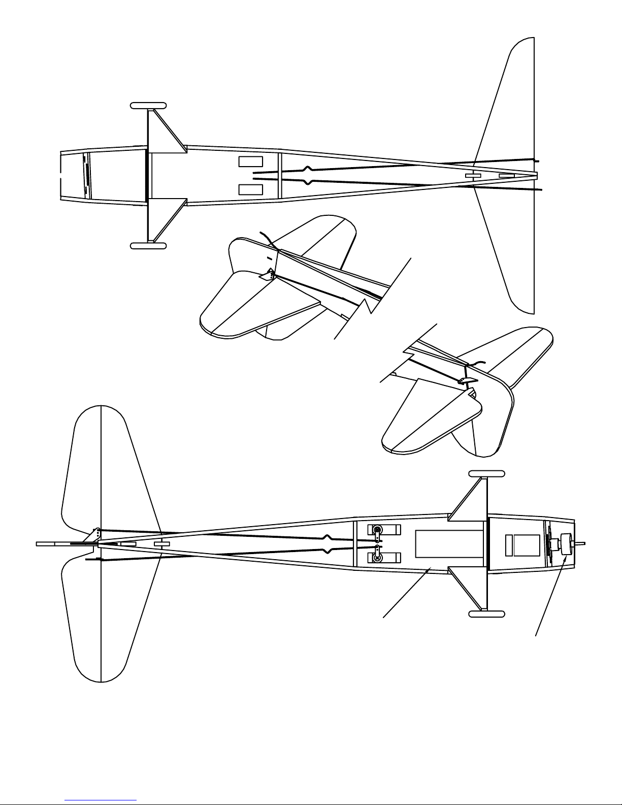
Step 19: Slide the elevator
onto the elevator pushrod and use
tape to hinge the elevator to the
stabilizer.
Step 18: Slide the elevator
and rudder pushrods into the
fuselage, as shown in the drawing.
The adjustment "V" bends go
inside the fuselage.
Step 20: Slide the rudder onto
the rudder pushrod and use tape to
hinge the rudder to the vertical.
Step 21: Mount the servos in
the fuselage, as shown. Slide the
servo horn onto the Z-bend in the
pushrod and secure the servo horn
to the servo.
Step 22: Mount the ESC and
receiver in the location shown in
the drawing.
Step 23: Use the included
Velcro to mount your battery as
shown in the drawing.
RX goes against
the fuselage
side.
BATTERY
ESC
Step 24: Mount the motor
mount to the firewall, using the
included #2 screws. Mount the
motor to the motor mount and
secure the set screws.
Page 9
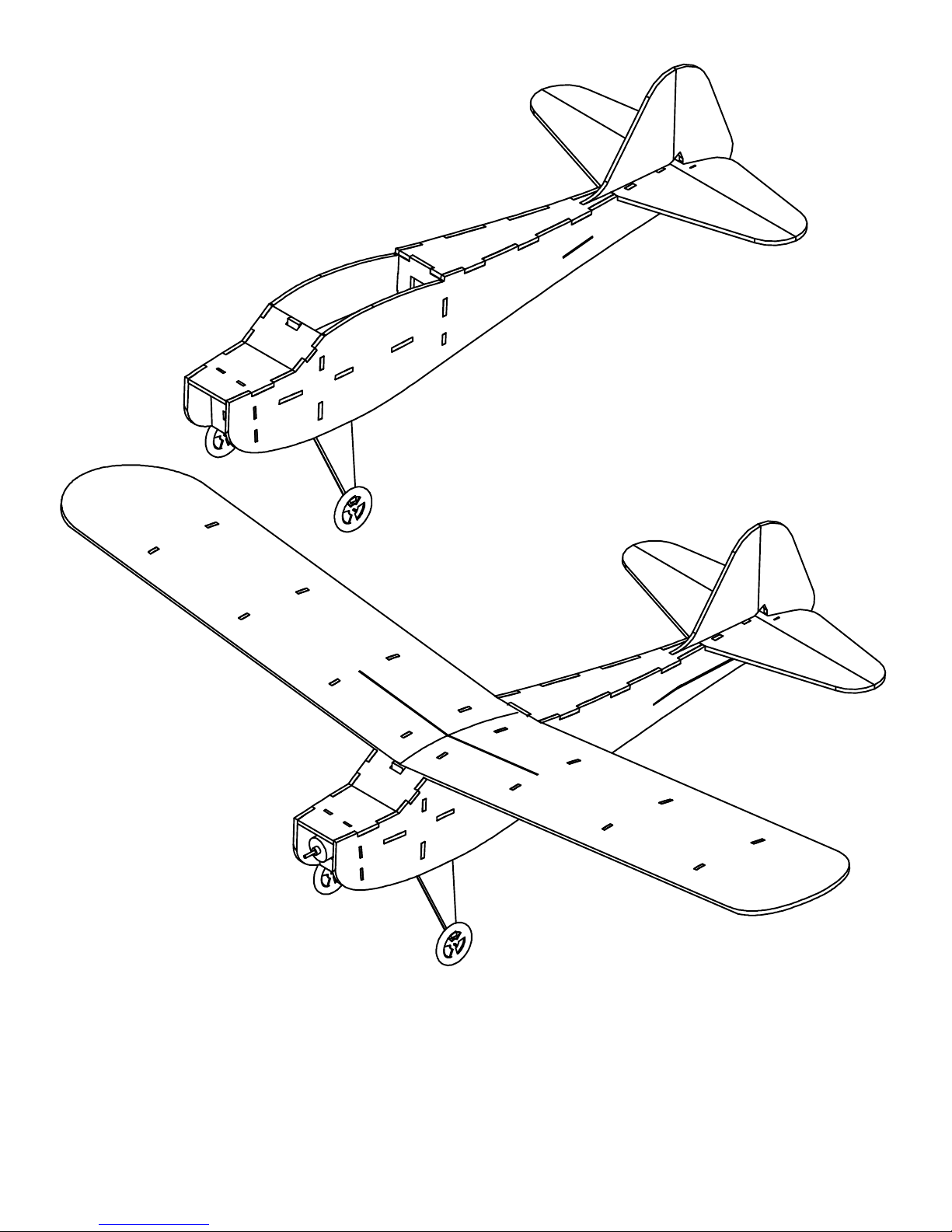
Step 25: Hook up your radio
and make sure everything works,
the servos are centered, the rudder
and elevator are centered, and
your controls are moving the right
direction.
Step 27: Set your control throws to:
LOW RAETS:
Rudder: 3/8" each way
Elevator: 5/16" each way
HIGH RAETS:
Rudder: 3/4" each way
Elevator: 3/4" each way
Step 26: Glue the wing onto
the fuselage, making sure it is
centered. You may need to trim
just a little off the front former so
it sits flat.
Step 28: Balance the plane at
1.5" behind the leading edge of the
wing.
Page 10
 Loading...