

SwitchBack Senior
SwitchBack Senior Specifications
Wingspan: 55.4 in.
Length: 41 in.
Wing Area: 597 sq. in.
Weight (Ready to Fly): 34 to 37 oz.
Wing Loading: 8.2 to 8.9 oz. / sq. ft.
Version 1.05, March 3, 2008

Thank you for purchasing the SwitchBack Sr. This plane is an aileron/elevator/rudder (full
house) setup, designed for the intermediate and higher pilot who wants a plane with
outstanding sport flying performance. Well… that and the SwitchBack groupie in all of us!
This kit is meant for beginner to intermediate builders and low-intermediate pilots (such as a
low wing aileron trainer) and on up for piloting experience.
We started with the original ever so popular SwitchBack, enlarged it by 50%, updated the
construction techniques, and slightly tweaked the design for an even better performing model
than the original.
Sincerely,
Brian Eberwein
sales@mountainmodels.com
Mountain Models guarantees this kit to be from defects in material and workmanship for the
original purchaser. Since we have no control over the assembly of the final model, we accept NO
liability for any damage or harm caused by the final product resulting from the user. By building
this kit, you accept sole responsibility and liability from its use.
If you, the original buyer are not prepared to accept the liability associated with the use of this
product, return the kit immediately in new and unused condition to us for a refund.
Mountain Models reserves the right to change or modify this warranty without notice.
WARRANTY
Mountain Models
PO Box 6815
Colorado Springs, CO 80934
www.mountainmodels.com
Phone: 719.630.3186
2

Before You Begin
Before you begin building your SwitchBack Sr., make sure that all the balsa sheets and
hardware are present in your kit. In the unlikely event that something is missing, please contact
us immediately and we will send it to you right away.
Make sure you read and understand all of the instructions thoroughly before beginning
assembly of this kit.
Additionally, you will need to have the following items. Check to make sure that all of your parts
are there and in good shape, and review a couple quick building tips to make this whole process
go quicker and easier.
Recommended Electronics:
• 3 ea. HS-81 Servos (2 x Ailerons, 1 x Elevator)
• 1 ea. HS-85 Servo (Rudder)
• 2 ea. 6” Servo extensions
• 1 ea. Y-Servo Connector (if using 1 channel for ailerons)
• 1 ea. Mini Receiver (6+ channel for using 2 aileron servos without Y-Connector)
• 1 ea. Scorpion 3008-32 Brushless Outrunner (or 200-300 watt equivalent)
• 1 ea. 3S-2000 LiPo Battery (or higher capacity)
• 1 ea. 35A Electronic Speed Control
Tools You Will Need:
• Smooth and FLAT work surface
• Plastic wrap or Wax paper to protect the work surface
• Thin and Thick Cyanoacrylate (CA) glue
• 5 to 10 Minute Epoxy
• Hobby knife with #11 blades
• Needle nose pliers
• Wire cutters
• Sanding block with 220, 320, and 400 grit sandpaper
• Sealing iron for applying the covering
• Soldering Iron
• Screwdrivers
Items for Finishing:
• 2 Rolls SoLite, Solar Film, or similar lightweight covering
• SolarTrim for adding details to your covering job
• Balsa Wood Filler, lightweight
3

Parts List:
• This Manual … If you do not have the manual you are holding, please call us. ☺
• Laser Cut Wood
• 2 ea. Red Pushrod Housings
• 2 ea. 1/16” x 24” Wire
• 2 ea. 1/16” x 12” Wire
• 1 ea. 0.047” x 9” Wire
• 2 ea. 0.060” x 24” Carbon Fiber Rod
• 2 ea. 1/8” Pre-Bent Landing Gear Wire
• Plastic Vac-Formed Canopy and Cowling
• Parts Bag
o 7 ea. 1/16” x 4” x 24” Balsa
o 4 ea. 1/16” x 3” x 24” Balsa
o 4 ea. 3/32” x 4” x 24” Balsa
o 4 ea. 1/8” x 4” x 24” Balsa
o 2 ea. 1/8” x 3” x 24” Balsa
o 2 ea. 3/16” x 4” x 24” Balsa
o 1 ea. 1/8” Plywood Sheet
o 2 ea. 1/8” Lt Plywood Sheet
o 1 ea. 1/16” Plywood Sheet
o 1 ea. 1/8” Plywood “loose” part
o 8 ea. EZ Hinges
o 4 ea. EZ Servo Connectors
o 8 ea. 4-40 T-Nuts
o 8 ea. 4-40 x 3/8” Machine Screws
o 2 ea. 10-32 T-Nuts
o 2 ea. 10-32 Nylon Bolts
o 2 ea. 2” DuBro Wheels
o 1 ea. 1” DuBro Tail Wheel
o 2 ea. 1/8” Wheel Collars
o 4 ea. Magnetic Washers
o 4 ea. Non-Magnetic Washers
o 4 ea. #2 Cowling Mounting Screws
o 3/16” x 5” Dowel
o Double Sided Velcro “Battery Seatbelt”
o 6” Sticky Backed Velcro
o 4 ea. Wire Ties
4
General Building Tips
• Balsa is a lightweight and fragile wood, so you do need to be careful with it; however,
you will also need to use a little bit of force to make everything fit properly, so don’t be
too timid.
• Join all of your pieces using thin CA (Cyanoacrylate) glue, unless we tell you otherwise.
In general, only a small amount of CA is necessary to glue parts together.
• Don’t remove any pieces from the balsa sheets until they’re ready to be used. That way,
parts won’t get mixed up or disappear.
• After you remove pieces from the balsa sheets, carefully remove any of the extra
material from where the piece was attached.
• Don’t over force your pieces together. If they aren’t going together properly, make sure
you have the right pieces and that they are oriented correctly.
• If you want to remove the charred edges caused by the laser cutting process, dampen a
cloth with bleach and gently rub the affected areas. Removing the char will not increase
the strength but will make it look better.
Assembly Instructions
Experienced builders may notice that this building order goes
against the “normal” building conventions. We have found that fewer pieces get mangled this
way, since you are building the stronger pieces first. For example, the tail feathers are at the
end of the build process instead of the beginning, so that they are less likely to get underfoot
(which seems to be a recurring problem) and are being built right before they are attached to
the fuselage and each other.
Section 1: Assembling the Fuselage
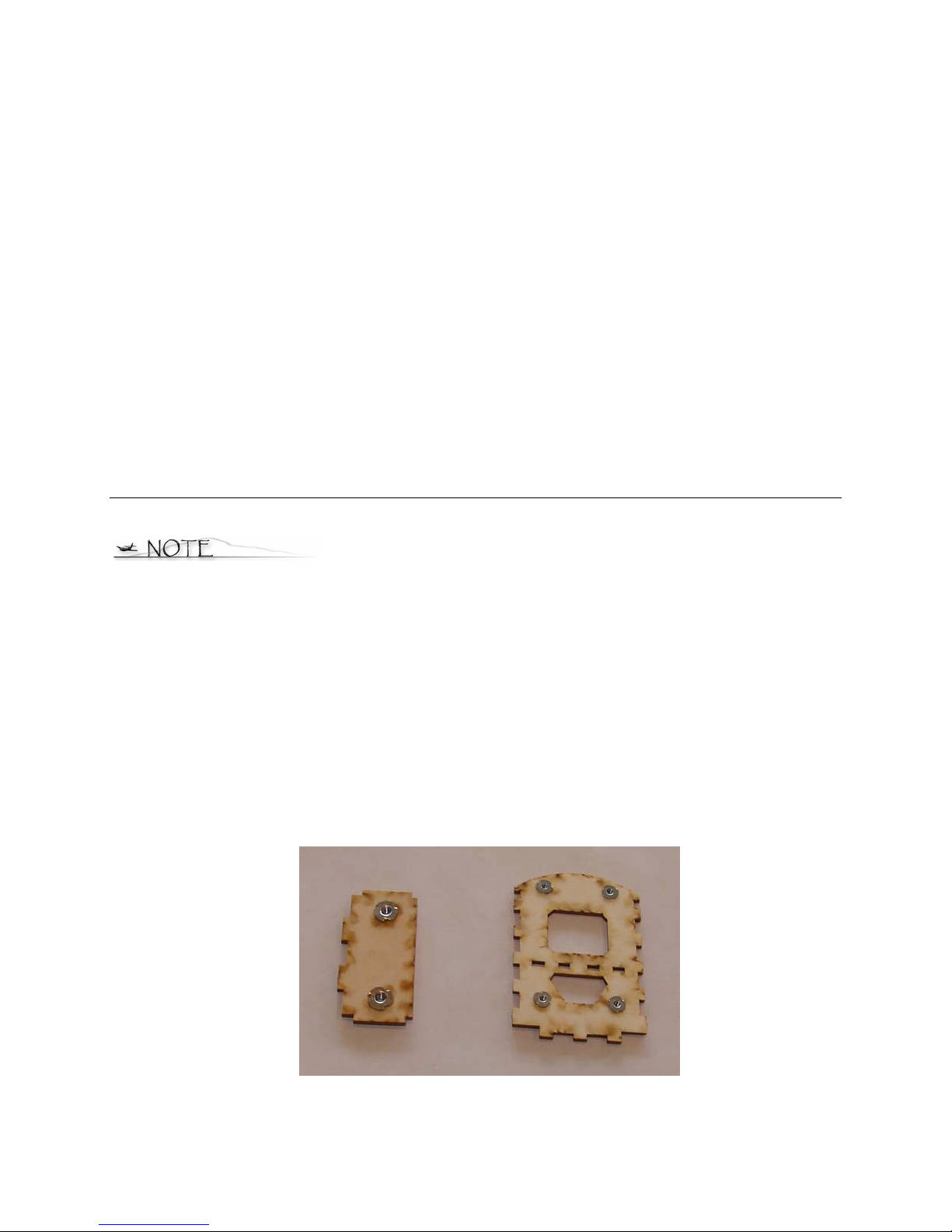
1. Press the 4-40 blind nuts into the front former and the 10-32 blind nuts into the fuselage wing
mount as shown below. There are 2 plywood circles on the sheet next to the wing mount.
These are to place behind the wing mount when installing the blind nuts so they don’t go into
your table. They are not glued into place. Make sure to install the blind nuts on the “dirty side”
of the parts. Secure the blind nuts with thin CA AFTER you are sure they are fully seated and
flat against the wood.
5
To remove the pieces, gently flex the balsa sheets until the pieces fall out.
You may find that you need to carefully trim the extra pieces of wood that
originally held the piece to the sheet.
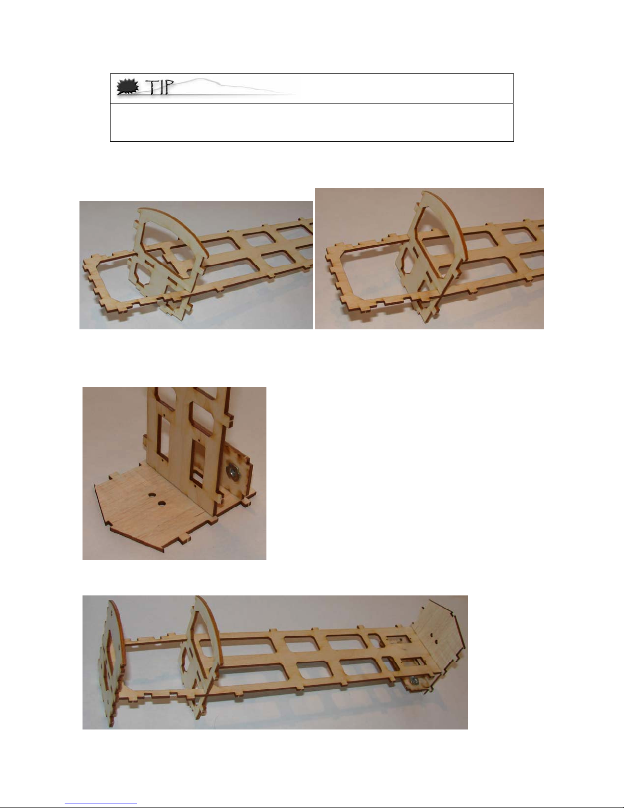
2. Slide the 1/8” Lt. Ply former into position on the 1/8” Plywood crutch as shown below. It is a
fairly tight fit, so work it back into position a little at a time. Do NOT glue them together yet.
3. Press the crutch from step 2 and the fuselage wing mount into the 1/8” balsa former as shown
below. Make sure the blind nuts are facing as they are in the image! It’s easiest to lay the
former on your table and press the crutch into the slots. Do NOT glue yet.
4. Press the crutch onto the 1/8” Lt Ply F1 as shown below. Nope, no glue here either.
6
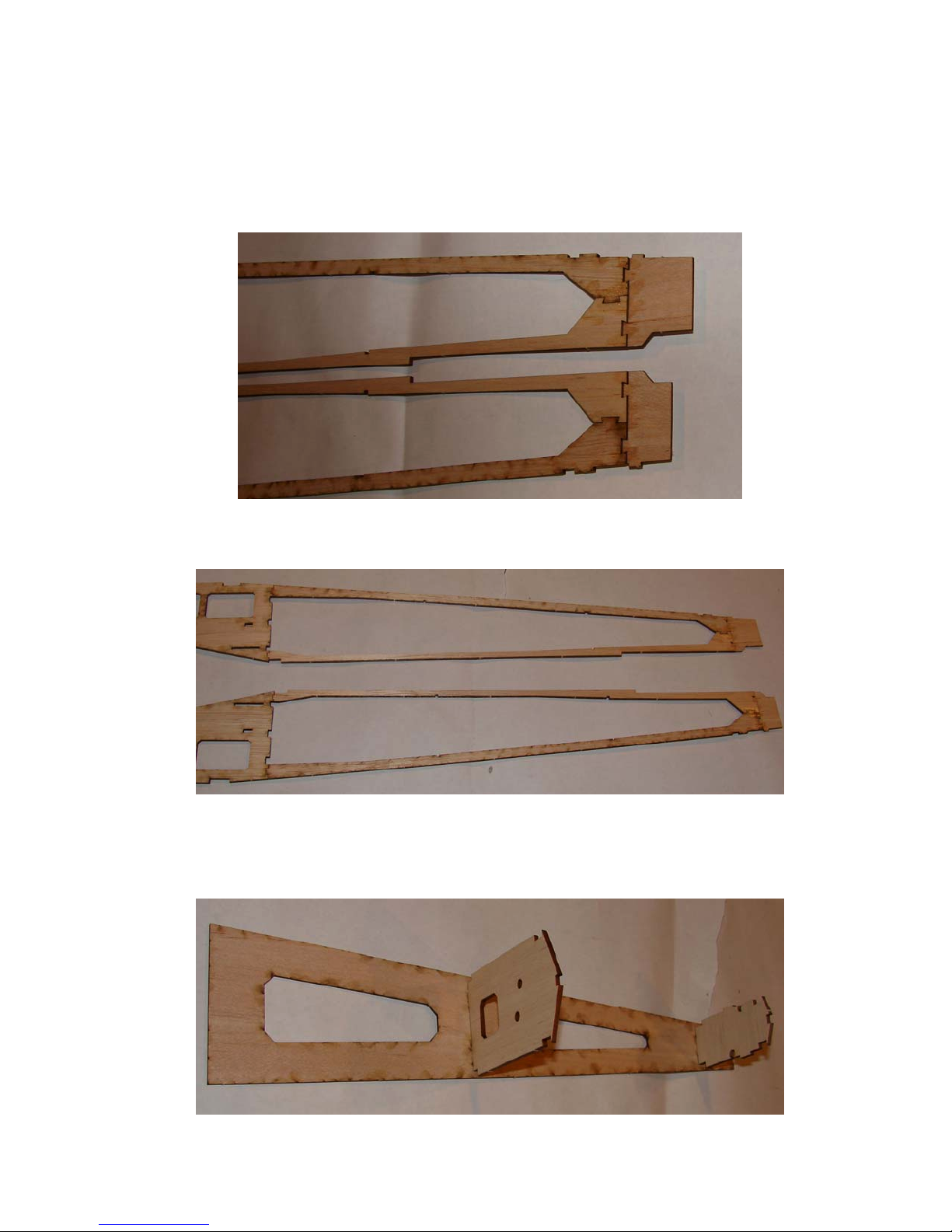
5. Assemble the 1/8” balsa rear longerons as shown below. The parts fit best when you assemble
the top/bottom parts with one of the lasered sides up and the other down. Lay them on your
table as shown below so you make a LEFT and RIGHT side. Press the assembled 1/8” rear fuse
parts onto the 1/16” balsa rear parts as shown below. MAKE SURE you assemble them as
shown below, and not upside down! Also make sure that the parts are flush on one side.
Secure these parts with thin CA.
6. Assemble the rear parts to the front 1/8” fuselage parts, as shown below. Place only a couple
drops of thin CA at the joints. Between the front and rear fuselage parts.
7. Press the 3/32” balsa formers into the 1/16” balsa bottom as shown below. The “lasered” side
of the bottom goes “up” and the “lasered” sides of the formers face aft. MAKE Sure this is
right. Lightly tack the parts together with a couple drops of thin CA, AFTER you make sure
they are fully pressed into place.
7
8. Press the 1/8” fuselage sides onto the fuselage crutch as shown below. MAKE SURE that the
rear “flush” area of the 1/8” and 1/16” balsa parts is facing to the outside. Do NOT glue this
yet.
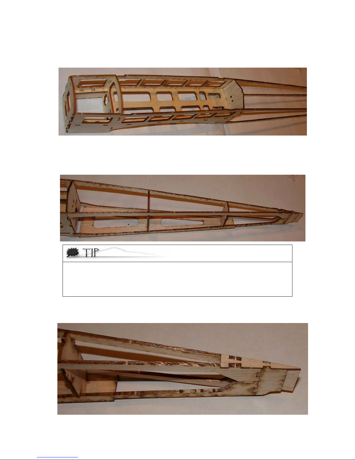
9. Set the assembly from step 7 on the table with the fuselage crutch assembly. Carefully slide
the rear /8” longerons into the slots in the formers. You may have to slightly bend and “crack”
the rear longerons where they attach to the front 1/8” balsa sides. You should end up with an
angle, rather than a curve at the joint with the 1/8” balsa former.
Be careful to keep your fingers as far away from the glue as possible; otherwise,
you might become a part of the model permanently. If you do get stuck, remove
yourself as carefully as possible, trying to avoid taking any of the wood with you.
Once separated, remove the CA glue from your fingers using nail polish remover or
acetone, making sure you wash your hands thoroughly when done.
10. Install the 1/16” balsa rear top part as shown in the image below. This part is somewhat
fragile until it is installed, so be careful when you are pressing it into place.
8
11. Weigh the fuselage down to the table to make sure it stays flat and straight and secure all the
joints with thin CA. ENSURE that the 1/16” balsa rear fuselage bottom is flush with the 1/8”
balsa longerons when you glue these together. Pull the sides together at the front of the fuse,
making sure they are fully pressed into the front former nd secure this area with thin CA.
12. Slide the 1/8” balsa part into place as shown below. Make sure it is flush with the sides and
secure with thin CA. This part is on the 1/8” balsa sheet with one of the fuse front sides.
13. Press the 1/16” balsa sides in place, with the “lasered” side to the inside of the fuselage. You
can use thick CA to glue these sides on, or you can use thin CA after they are on, making sure
they are fully pressed into place. Weights help make sure the sides are fully pressed into
place, as shown below.
¼” Steel plate cut to about 4” squares makes GREAT weights for building. They are
useful for many areas of building and are invaluable took in our shop. Call around
town and see if you can find a metal shop that might have some scrap they can cut
for you. You’ll love having these around. You can also use some 1” square aluminum
tube filled with lead shot and epoxy, bags of lead shot, and even a stack of old
magazines for weights.
9

14. Press the rear 1/16” sides into place with the “lasered” side of the part to the inside of the
fuselage, as shown below. BEFORE you glue anything, check to see if the pushrod exit slots
line up with the holes in the rear 3/32” former. If they don’t, you have the parts on the wrong
side. Secure the sides with thin CA.
15. Install the 3/16” rear spine into the formers as shown below. Make sure it is fully seated and
secure it with thin CA.
16. Press the 1/8” plywood landing gear supports into place as shown below. The “lasered” sides
should face to the inside of the fuselage. Clamp them, or otherwise make sure they are fully
pressed into place and against the sides while the glue is drying. If you’re fast, you can use
thick CA. If not, then use some 5 minute epoxy, spread thin.
10

17. Install the 1/8” Lt Ply part as shown below. MAKE SURE that the holes for the landing gear
wires match up with the landing gear supports from step 16. If the holes don’t line up, you will
NOT be able to install your landing gear. Now that would really be a pain, wouldn’t it? After it
is glued into place, install the 1/8” Lt Ply bottom as shown below, ONCE AGAIN, making sure
that the holes for the landing gear wire line up.
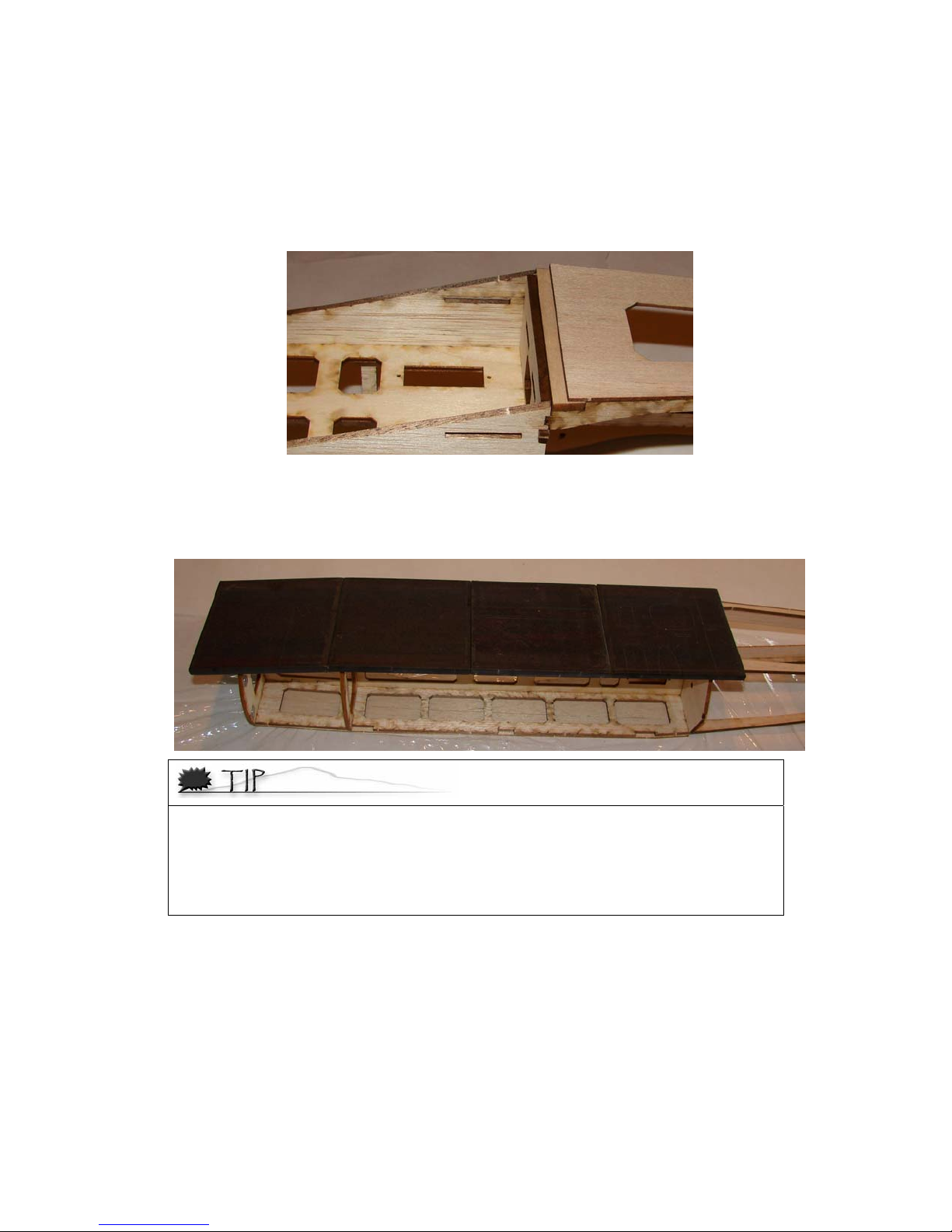
18. Install the 1/16” balsa rear deck, as shown below. Make sure that it lines up with the front of
the 3/16” spine. The deck sits on top of the inside 1/8” longerons and inside of the 1/16” balsa
sides. You’ll have to lightly bend the front of the 1/16” sheet to sit in the forward area.
19. Glue the MAGNETIC washers to the 1/8” Lt Ply canopy hold down plates, using the etched
circles for placement. Glue the canopy hold down plates in the fuselage as shown below.
11

20. Glue the 1/8” Lt Ply cowling mount parts into the front former as shown below.
21. Place some tape behind the second former to protect the fuselage sides. Sand the top front of
the fuselage sides to follow the curve of the front 2 formers. Line up the 1/16” top front balsa
sheet, so there is the same amount of material hanging off on each side. Lift up one side and
tack down with thick CA. Then glue the other side with thick CA as well. Sand the sides of the
front top sheet to be flush with the fuselage sides.
12

22. Glue in place the 1/16” plywood tail wheel wire support as shown below.
23. Install the Red pushrod housing through the holes in the aft 3 formers. They should come
forward of the front former by 1/8”. Secure them with thin CA and then trim them flush with
the fuselage sides where they exit in the rear.
24. Sand the forward part of the 1/8” balsa part, just aft of the rear former so it is flush with the
fuselage sides, as shown in the top right image.
25. Sand the front and rear bottom corners of the fuselage, round the top rear center, and round
the top of the fuselage sides where they meet the top rear deck. Test fit your canopy and
cowling to make sure you have rounded the corners enough for the parts to fit properly. Fill
any voids with lightweight filler and then lightly sand the entire fuselage with 320 grit and
then 400 grit sandpaper.
13

Section 2: Assembling the Wings
1. Assemble the 1/8” balsa spar as shown in the image below. Make sure the parts are fully
pressed together and secure with thin CA.
2. Insert the 1/8” center ribs and the 1/8” front half-ribs as shown in the image below. The 1/8”
ribs are on the sheet that had the front fuselage sides on it. They have 1 slot at the bottom
rear of the ribs. Do NOT glue them yet.
3. Insert the 1/8” plywood center front part into the ribs. Do this a little at a time. It will be
necessary to spread the full ribs out of the way while you slide it into place, as shown in the
above right image. After it’s fully seated into the ½ ribs, press the full ribs onto it. Do NOT
glue it yet.
4. Insert the 1/8” balsa rear ½ ribs into the spar as shown below, but do NOT glue them yet.
14

5. Press the 3/32” balsa servo wire guide into place between the rear half ribs.
6. Press the 1/8” balsa support into the rear ½ rib tabs as shown in the upper right image. You’ll
need to spread the back of the 1/8” full ribs to get the tabs on the part into the ribs.
7. Install the 1/8” Lt Ply rear center section as shown below. Make sure the center section is
square and secure the parts with thin CA. Glue the 2 1/8” balsa parts into place using thick CA
sh shown below, making sure that the bolt holes are lined up.
8. Press the 3/32” servo mounting area ribs into place. These ribs have slots in the bottom to
accept the servo mounting plate.
15

9. Insert the rest of the 3/32” balsa ribs onto the spar, making sure all of the ribs are pressed
fully in place.
10. Sand Slide the 3/32” balsa leading edge support into place on the ribs on one side of the wing.
MAKE SURE you install it in the right direction. The side with 2 tabs goes toward the center of
the wing. Work a little bit at a time, pressing it just into the ribs along the wing, then start at
the center working out, pressing in further. Repeat until it is fully pressed into place.
11. Press the 3/32” balsa T.E. supports into the 1/8” trailing edge as shown below. The 3/32”
parts were next to the leading edges used in step 10. LOOK AT THE PARTS! One end has an
angle on the 1/8” parts, which goes toward the center section of the wing. Set them next to
each other so you make a LEFT and RIGHT side. The end of the 3/32” parts with the shorter
tab also goes toward the center section. Lightly tack these parts together with thin CA.
16

12. Press the parts from the previous step into place on the back of the ribs, as shown in the
image below. MAKE SURE that the angled end goes towards the center section and is on the
correct side. Press it into place a little bit at a time until all the ribs are fully seated and it is
plugged into the center 1/8” rib.
13. Press the outboard 1/8” balsa ribs into place. These are on the sheet with the canopy frame.
14. Slide the 1/16” plywood spars into place as shown in the images below. Note that the top and
bottom spars are different shapes. Make sure they are flush with the spar and glue them in
place with thin CA after they are in position.
17

15. Slide the 1/16” leading edge parts onto the wing as shown. Work a little at a time along the
wing, until it is fully seated against the leading edge support and the ribs. PAY ATTENTION to
these parts. The ends of the outboard parts have an angle to them to match the dihedral
angle of the wing. These ends go towards the center. Add the center 1/16” part as well.
16. Slide the 3/16” leading edge parts onto the wing as shown below. Make sure they are all fully
pressed in place and lightly tack with thin CA.
17. MAKE SURE that the wing panels are straight and all parts are fully seated and lined up. After
you are SURE, secure all parts with CA, double checking as you go to make sure the parts are
still seated before you add the glue to an area.
18. Install the top center wing sheeting. The front of the wing sheeting rests on the 1/16” leading
edge part, and in front of the 3/16” leading edge part. Secure with thin CA. Repeat for the
bottom center wing sheeting.
18

19. Test fit the bottom right wing sheeting and weigh down the wing as shown. Weigh the wing
down and secure the sheeting along the back of the spar with thin CA. Pick up the wing and
glue the rest of the lower sheeting into place along the front. The sheeting rests on top of the
1/16” leading edge and in front of the 3/16” leading edge parts. Make sure that the sheeting is
fully pressed onto the tabs on the ribs and sits flush with the 3/16” leading edge part.
20. Weigh down the right side of the wing and make sure it is straight and flat. Test fit the top
wing sheeting. Start by gluing down the front of the sheeting with thin CA, with the back
sitting up slightly, as shown in the image below.
21. You can glue the back of the sheeting with thick CA (if you’re fast), or white glue. If you use
white glue, weigh down the sheeting while it dries to make sure you get a good bond.
22. Repeat steps 19 to 21 for the Left side of the wing.
19

23. Glue the 3/32” wing tip supports in place as shown in the image below. The shorter of the 2
goes on towards the rear. Secure lightly with thin CA after making sure they are fully pressed
into place. Make sure you make a left and right version. Put these in place on the wing tips as
shown in the second image, making sure they are pressed fully into place and secure them to
the wing with thin CA.
24. Install the 1/16” plywood servo mounts in the wing as shown below, using thick CA. Glue in
the 1/8” balsa servo mount doublers on the inside of the wing on top of the plywood mounts
with thick CA.
25. Sand the leading edge to finish the airfoil shape. DO NOT NICK THE plywood wing mounts in
the center section. Wrapping these with tape while sanding is a good idea. A good
approximation on where to sand is by starting out sanding tangent to the wing sheeting at the
back and go down to the front tabs. Then gently round off the tab area of the leading edge.
Sand the leading edge at the tips to match the wing tips. It will look like the next image when
you are done.
20

26. Sand down the rear center section balsa blocks for the wing bolts to match the rib profile on
either side of them. Laying some tape on the ribs will help keep you from sanding into the ribs
themselves.
27. Lightly sand the entire wing with 320 and 400 grit sandpaper. The smoother the sanding job,
the better the covering will look.
28. It is a VERY GOOD IDEA to run a string from the servo box up through the servo wire hole in
the center of the wing, so you can fish the servo wire out the wing after it is covered. Tape the
string in place just to the inside so you can get to it after cutting out the holes in the covering.
Section 3: Assembling the Ailerons
1. Build both ailerons at the same time to make sure you make a LEFT and RIGHT aileron.
2. Press the 3/32” aileron ribs into the 1/16” aileron sheet as shown below. The center ribs are
made up of a 1/16” balsa rib between 2 of the 3/32” ribs. Do NOT glue them in place yet.
3. Press the 1/16” top front part in place as shown below. Make sure the aileron is flat and
secure the parts in place with thin CA.
21

4. Assemble the 3/32” aileron leading edge parts together as shown. ENSURE that they are
straight and fully secured, using weights or rulers, and secure with thin CA.
5. Glue the aileron leading edge in place on the aileron as shown. Make sure it is FLAT and
STRAIGHT, weighing it down while it is glued.
6. Trim the Carbon Fiber rods to length and glue them to the trailing edge of the ailerons with
thick CA. Keep your aileron flat while you are doing this or you’ll end up with a permanent
warp!
7. When done, you should have a LEFT and RIGHT aileron as shown.
22

Section 4: Assembling the Stabilizer, Elevator, Vertical Fin, and, Rudder
8. Press the parts together as shown. After the parts are assembled and flat, secure each joint
with a drop or 2 of thin CA.
23

9. Cut the 3/16” dowel to 4-1/8”. Slightly roughen the dowel with some 220 grit sandpaper for a
better glue bond. Join the elevator halves with the dowel using 5 minute epoxy.
10. Lightly sand each side of the tail parts with 320 and 400 grit sandpaper.
11. Sand a 45 degree “V” in the hinge side of the rudder. It will look something like the image
below.
12. Sand a 30 to 45 degree bevel in the horizontal stab for the hinge line.
13. Sand round the outside edges of the vertical, rudder, stab, and elevators. It looks a lot better
round, instead of leaving it squared off.
Shaping the Tail Wheel Wire and Attaching it to the Rudder
Needle nose pliers work pretty well to shape the wire.
1. Bend the 0.047” wire as shown below. This drawing is to scale.
2. Cut one of the CA hinges in half lengthwise. Wrap one piece of it around the landing gear wire
as shown. Use some plastic wrap or wax paper over the hinge and squeeze it together with
some needle nose pliers to make sure it stays as thin as possible.
24

3. You do NOT attach the tail wheel until the rudder is attached to the vertical fin after covering
and hinging the rudder to vertical. Drill a hole in the rudder for the wire to press into and cut a
slot in the rudder for the hinge that is attached to the tail wheel wire. Slightly indent the balsa
rudder where the rest of the wire rests. Press the wire into place and secure it with thick CA.
Use some thin CA on the hinge material to make sure it is properly adhered to the rudder.
Section 5: Assembling the Canopy
You are going to assemble and attach the canopy base, which once in place will be used to hold
the plastic canopy in place.
1. Position the 1/8” balsa cross braces in the canopy base. Press the 4 magnets into the holes,
making sure they are flush on the “lasered” side of the canopy base. Glue in the magnets with
thin and thick CA.
2. Trim the canopy plastic so you have about 1/8” to 3/16” overhand on the front, back, and
sides of the fuselage.
3. Set the canopy frame in the fuselage and the canopy over it. You’ll need to slightly sand the
front sides of the frame so the canopy sits properly on it. Do this a little at a time until you
have a good fit. Slightly roughen up the inside of the canopy sides where the balsa meets it so
you can get a good glue bond.
4. Set some plastic wrap in the fuselage canopy area to keep you from gluing the canopy base to
the fuselage. Set the canopy frame in place and glue the canopy to the canopy frame using
Canopy Glue or 5-minute epoxy. Do NOT use CA to glue the plastic. CA would make it brittle.
25

Section 6: Covering
Covering the SwitchBack Sr.
Determine what material you’ll use to cover, we recommend using Solite or SolarFilm covering
material since it is extremely lightweight and won’t crush the balsa when shrinking. Please refer
to the instructions that came with your covering for details on how to cover if you haven’t done
it before.
Following your covering material instructions, cover the pieces in this order:
Do not shrink the covering until both sides of each part are covered. This reduces your
chances of twisting the surfaces.
• Wings (Trim out covering for servos and servo wires
• Fuselage (Cut out the aft bottom lightening hole for an air exit)
• Ailerons
• Tail Feathers
• Control Horns (Looks a LOT better than leaving them uncovered!)
Cutting the Slits for the CA Hinges
You need to cut slits into the tail feathers and ailerons to allow for the CA hinges to be
attached.
• Cut the rest of the CA hinges in half, lengthwise . Cut 1/2” wide slits into the ailerons,
wings, stabilizers, elevator, and rudder. The slits in the tails should be exactly
centered into the thickness of the wood. The rudder gets 3 hinges; one ¼” down
from the top, one just above the rudder horn slot, and one ½ way between the other 2.
The elevators/stab get 2 hinges per side, one about ½” in from the tips, and one 1bout
½” away from the dowel. The ailerons get 3 hinges each, one about 1” in from each end,
and one in the middle. For the aileron slits, cut them in the ailerons first and then lay
out the ailerons to see where the corresponding slits need to go into the rear of the
wing.
Section 7: Installing the Tail Feathers
For this step, you are going to install the horizontal stabilizer, elevator, the vertical
stabilizer and the rudder to the fuselage.
Attaching the Horizontal Stabilizer
• You need to remove some of the covering on the horizontal stabilizer so that you can
securely attach it to the fuselage. Set the stabilizer onto the bottom of the fuselage,
making sure it is centered on the fuselage. Mark the elevator to show where you need to
trim the covering. You need to remove the covering so you get a strong balsa to balsa
glue joint. Use a sharp blade and try not to cut into the balsa itself.
• Make sure the stab is centered on the fuselage and flat with the bottom of the fuselage
and glue it in place with 5 minute epoxy or thick CA.
26

Installing the Elevator
• Install the CA hinges into the slots in the stabilizer and slide the elevator onto the CA hinges,
so half of the hinge is in each part. Move the elevator through its full range of motion and then
secure the hinges by placing a few drops of thin CA on both sides of the hinges at the hinge
line. Keep flexing the elevator to keep the CA from gluing the covering of each part together.
Attaching the Vertical Stabilizer and Installing the Rudder
• Run a bead of thick CA along the top of the fuselage sides where the vertical stabilizer
will rest, and position the vertical stabilizer, making sure that the rear of the stabilizer
lines up with the rear of the fuselage and that it’s perpendicular to the elevator. Hold in
place until the CA sets. (See image at top of page)
• Position the three hinges into their slots on the rudder. Slide the tail wheel wire though the
hole in 1/16” plywood part on the back bottom of the fuselage. Maneuver the rudder so that
one by one, the hinges can be lined up and slid into the slots in the vertical stabilizer.
• Glue the hinges into place with thin CA as you did with the elevator and stab.
Attaching the Ailerons
Attach the ailerons to the wing using the same method you used to attach the tail feathers. You
will use 3 half CA hinges per aileron.
aileron when you are attaching them to the wings. The aileron control pockets need to face
down.
Make sure that you pay attention to which is the left and right
27

Section 8: Attaching the Control Horns
Next, you are going to attach all of the control horns, you will need:
• 1 Elevator control horn
• 1 Rudder control horn
• 2 Aileron control horns
Insert the control horns into their appropriate pocket. The Rudder control horn goes on the
RIGHT side and the elevator horn goes on the LEFT side. Left and right is as if you were
sitting in the cockpit looking forward. After checking to make sure that they’re aligned
properly, glue them into place with thin CA.
Section 9: Installing the Servos and Control Rods
1. The tail feather servo holes in the plywood crutch are sized for HS81 size servos.
2. Place the servos in the holes with the control horns towards the front of the fuselage. Screw
the servos into place and then remove the screws and servos. Flow some thin CA into where
the servo screws screw holes to strengthen the wood, creating tough “threads”. Allow the glue
to dry completely and then reinstall the servos and screws. Do not over-tighten the screws.
3. Do the same procedure for the aileron servos. The control horn ends should be facing towards
the ailerons. You’ll need to thread the servo wires with extensions through the wing. Place a
strip of tape around the connectors to keep it from coming unplugged.
28

4. Put an EZ Servo connector in each of the servo control horns.
5. Place Z-Bends in the ends of each of the 2 - 24” and 2 - 12” 1/16” diameter wires.
6. Place the Z-bend ends of the 12” wires into the plywood aileron control horns.
7. Slide the aileron servo horn EZ Connector onto the wire and then onto the servo. With the
aileron neutral, secure the control rod in the EZ Connector with the screw.
8. Trim off extra wire about 1-4” on the other side of the EZ connector.
9. Thread the 24” 1/16” wire through the pushrod housings with the Z-Bend in the front fuselage
area.
10. Install an EZ Connector on the plywood elevator and rudder control horns.
11. Slide the control wire through the EZ connector on the plywood control horn. Place the Z-Bend
through the servo control horn and place the control horn onto the servo.
12. With the control surfaces neutral, install and tighten the EZ Connector screw.
13. Trim off the extra wire about ¼” behind the EZ Connector.
29

Section 10: Landing Gear
• Slide the landing gear into the holes on the bottom front fuselage.
• Place a bend in the end of the wire ties and thread them up though the bottom and then
back out on the other side. Pull them tight and trim off the extra, as shown in the image
below.
• Slide the wheels onto the main gear and secure them with the Wheel Collars and set
screws.
• Slide the tail wheel onto the tail wire and secure it with some drops of thick CA on the
end of the wire. BE CAREFUL not to get CA in the wheel itself.
30

Section 11: Installing the Motor
We recommend a brushless motor rated for around 200 to 300 watts. The prototypes flew
outstanding on the Scorpion 3008 and 3S at around 250 watts.
! Installing the Motor
1. You will want to glue the mounts together with epoxy, rather than CA. Epoxy can handle the
vibration of a slightly out of balance propeller better than CA can.
2. Assemble the motor mount as shown in the photos. Make sure the parts are seated properly
to ensure the thrust angles are correct. All the parts are 1/8” Lt. Ply except for the 1/16”
plywood front doubler. The front parts have holes for the Scorpion motors. There are
additional ones marked with an X to help alignment if you are using a different brand motor.
3. Bolt the motor to the mount using the supplied 4-40 x 3/8” screws.
4. Bolt the motor mount to the firewall using 4-40 x 3/8” screws and the #4 washers.
31

Section 12: Attaching the Receiver and Speed Controller
! Attaching the Receiver
• The receiver is attached within the fuselage, in front of the servos. Use adhesive Velcro
and attach it to the ply crutch. Connect the servos and ESC to the receiver, following the
guides on the receiver itself.
! Attaching the ESC
• The speed controller can be attached behind the motor on the motor mount with wire
ties, or placed inside the fuselage.
Section 13: Finishing the Kit
Well, you’re almost there…the end is in sight; just a few more steps and you can go flying,
assuming the weather is cooperating.
Attaching the Nose Cowl
1. Trim the cowling from the plastic sheet. The easiest way to do this is to use sandpaper from
the back inside.
2. Trim out a hole in the front so the motor shaft can come through. Also trim out the cowling
vent in the front to allow air to flow through, cooling the motor, ESC, and battery.
3. Place the cowling on the front fuselage and use the 4 - #2 screws to fasten the cowling to the
cowling mounts.
Attaching the Wing
• Place the wing into the fuselage and secure it in place with the 10-32 nylon bolts.
Attaching the battery
1. The battery mount is the front section of the plywood crutch.
2. Determine approximately where the battery will need to be placed to establish your CG. Cut
the rough side of the Velcro strip down to 4 1/2" in length, and attach it to the top of the
battery mount so that it’s centered on the battery’s position.
3. Attach the soft side of the Velcro strip to the bottom of your battery pack.
4. After you attach the battery pack onto the mount, run the 6” double-sided Velcro strip
underneath the battery mount, around the top of the battery pack, and then secure it to itself
snugly. This acts as a seatbelt, holding the battery pack securely in place.
Typically, losing your battery in mid-flight is a bad thing…a very bad thing…
32

Setting the Throws
You need to adjust your radio trim so that the elevator, rudder, and ailerons are all level. The
throws are listed as total travel, and are as follows:
Low Rates High Rates
Ailerons
Elevator
Rudder
1” Full 45 degrees
1” ~45 degrees
2” As much as you can get
Setting the Center of Gravity
The Center of Gravity (CG) will affect how the airplane recovers from a nose up or nose down
condition (pitch stability). With the CG too far forward, the plane will be quite stable, but
require a lot of up elevator to fly level. This will result in an increased low end speed. On the
other hand, too far back and the plane will be hard to control, requiring constant input to keep
the plane flying straight and level. Start with the CG about 3-5/8” back from the leading
edge of the wing. Use this as a starting point. You can slowly move it back as you get more
comfortable with the plane.
33
 Loading...