

Page 1

Spook-E™ Micro
Micro Nostalgic R/C Electric Airplane
Spook-E™ Specifications
Wingspan: 23.53 in.
Length: 15.66 in.
Wing Area: 100 sq. in.
Weight (Ready to Fly): 1.8 oz.
Wing Loading: 2.6 oz. / sq. ft.
Version 1.0, April 9, 2012
Page 2

WARRANTY
Mountain Models guarantees this kit to be free from any defects in both material and workmanship at the
time of purchase. This warranty does not cover ANY components or parts damaged by use or modification.
In no case shall Mountain Model’s liability exceed the original cost of the purchased kit. Mountain Models
reserves the right to modify or change this warranty without notice.
LIABILITY RELEASE
In that Mountain Models has no control over the final assembly or material used for final assembly, no
liability shall be assumed or accepted for any damage resulting from the use by the user of the final userassembled product. By the act of using the user-assembled product, the user accepts all resulting liability.
If the buyer is not prepared to accept the liability associated with the use of this product, the buyer is
advised to return the kit immediately in new and unused condition.
THIS PRODUCT IS NOT INTENDED FOR CHILDREN 12 YEARS OF AGE OR YOUNGER.
WARNING: This product may contain chemicals known to the State of California to cause cancer and or
birth defects or other reproductive harm.
PRODUCT SUPPORT
This product has been designed to function properly and perform as advertised with the SUGGESTED power
system, speed control, and servos, as described in advertisements and in this manual. We do NOT support,
nor can Mountain Models assist in determining the suitability or use with any other electronics or hardware
not recommended by Mountain Models.
For the proper electronics to complete this model, replacement parts, and product assembly questions,
please contact Mountain Models online at www.MountainModels.com
Thank you for purchasing the Mountain Models Spook-E™ Micro. The Spook-E™ Micro is a micro model
designed with influence from the famous Spook, a classic vintake plane, to bring back that nostalgic feeling
of yesteryear, in an indoor electric package. The 23.5 inch Spook-E™ Micro is a super easy to build and
easy enough for a beginner to learn how to fly, with some friendly help.
The Spook-E™ was designed using a state of the art 3D CAD package, to allow for exceptional interlocking
parts design and fit. 3D design also allows us to provide clearer assembly images, without having to use
photos.
The Spook-E™ is built from self-jigging interlocking laser cut balsa and plywood parts. It's like a 3D jigsaw puzzle
with instructions. Although not needed for building, full size plans are included for reference. If the instructions are
read before hand and followed during the build, the Spook-E™ can be built up and ready to fly in only a few
evenings.
We think you’ll like the Spook-E™ and look forward to any feedback you might have.
Thank you,
Brian Eberwein
Mountain Models
2935 N Lynndale Drive
Appleton, WI 54914
www.mountainmodels.com
Phone: 920.840.6036
2
Page 3

Before You Begin
Check to make sure that all of your parts are there and in good shape.
Parts List
Number
in Kit
Bundled Parts
1 Laser Cut Parts Sheets (6 Sheets )
2 Plan Sheets (11” x 17”)
1 These instructions of course!
Metal (on the back of the wood bundle)
1 0.020 x 18” Wire
1 0.020” x 12” Wire
1 1/32” x 12” landing gear wire
Bagged Parts
2 Wheels
1 1/16” Aluminum Tube
1 1/16” x 1” Shrink Tube
1 1/8” x 2-1/2” Dowel
6 #16 Rubber Bands
Description of Part
Building Materials and Tools You Will Need
• Smooth and FLAT work surface
• Wax paper or clear plastic wrap to protect the work surface
• Thin Cyanoacrylate (CA) glue
• Hobby knife with #11 blades
• Needle nose pliers
• Wire cutters
• Sanding block, 320 to 400 grit sandpaper
• Covering Iron
Finishing Materials You Will Need
• SoLite Covering (Do NOT use heavier covering!!!!!!!!!!!!)
(You can use a light weight tissue covering instead of SoLite)
• Double-Sided Foam Tape
• Hinge Tape (DuBro or Similar)
• Velcro to Mount Battery
Electronics You Will Need
• Power: ParkZone Motor/Gearbox (PKZ3624) for UM P-51/Sukhoi
• Prop: EFL9051 Ultra Micro 130mm x 70mm
• RX/ESC/Servo: ParkZone ‘Vapor’ PKZ3351 or Spektrum AR6400
• 1S-130 mAh LiPo
3
Page 4

General Building Tips
• READ THE INSTRUCTIONS all the way through and study the plans BEFORE starting any
work on the model.
• PRE-SANDING: BEFORE removing any parts from the balsa sheets, use a sanding block
with 320 grit sandpaper and lightly sand the back of the balsa sheets. Our balsa suppliers
have been sending us wood that is over sized, so sanding the backs of the balsa sheets
reduces the thickness just slightly and removes any charring from the laser cutting process.
• Tape the plans to your nice clean work surface and cover it with wax paper or plastic wrap.
You want to keep your work surface clean and not glue the parts to the plans, right?
• Balsa is a lightweight and fragile wood, so you do need to be careful with it; however, you
will also need to use a little bit of force to make everything fit properly, so don’t be too
timid.
• Do not remove any pieces from the balsa sheets until they’re ready to be used. That way,
parts won’t get mixed up or disappear.
• Do NOT glue anything until told to do so.
• Join all of your pieces using thin CA (Cyanoacrylate) glue, unless we tell you otherwise. In
general, only a small amount of CA is necessary to glue parts together.
• Don’t over force your pieces together. If they aren’t fitting together properly, make sure you
have the right pieces and that they are oriented correctly. If needed, you can lightly sand
the part to fit after making sure it is the correct part and oriented correctly. On balsa “tabs”,
you can “pinch” the wood with your fingers to get them to fit in slots. (The tabs might be
tighter some times, due to tolerances in wood thickness)
• If you want to remove the charred edges caused by the laser cutting process, lightly
dampen a cloth with bleach and gently rub the affected areas. Removing the char will not
increase the strength but will make it look better. It also keeps that dark edge from showing
under the lightweight coverings. You can also remove it by LIGHTLY sanding with 400 grit
sandpaper.
4
Page 5
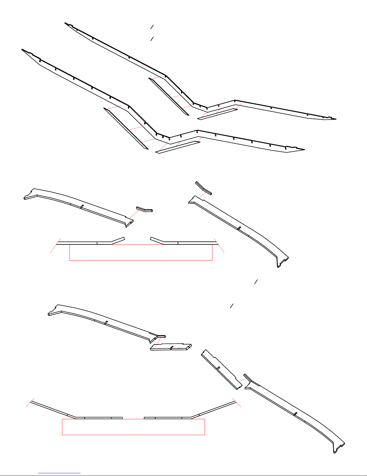
1. Join the
2. Join the
1
" balsa W1 and W1A parts together with thin CA, to make the main spar, W1.
16
1
" balsa W2 and W2A parts together with thin CA, to make the rear spar, W2.
16
3. Glue the plywood W1R spar reinforcements onto W1, with thick
CA. BE SURE to align them properly, as shown on the plans.
4. Glue the plywood W2R spar reinforcements onto W2, with thick CA.
BE SURE to align them properly, as shown on the plans.
W10
W2R
W1
W1R
W22
W22W10 W10W22
TABLE
W2
W2R
W1R
W22
W10
W9
TABLE
5. Glue the plywood W22 parts onto the
a LEFT and RIGHT as shown, with thick CA. Place the "dirty" side
3
" balsa W10 parts, making
32
of W10 "up".
6. READ THIS STEP!! Glue the
assembly, with thick CA. BE SURE to align them properly, and
3
" balsa W9 parts onto the W10/W22
32
make a LEFT and RIGHT. THE ENGRAVED TEXT ON W9 goes AWAY
from the W22 parts.
W9
W9
W9
Page 6
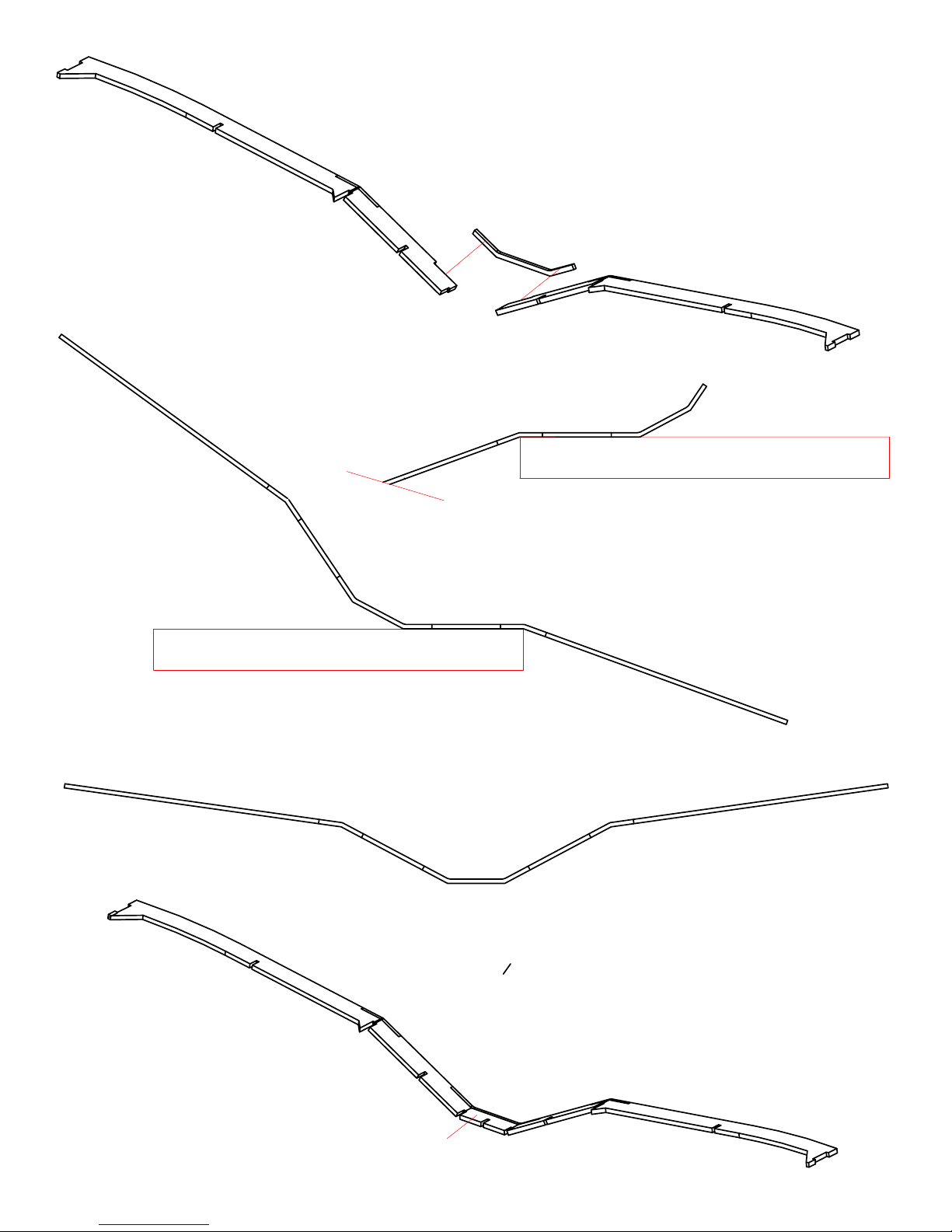
7. Glue the plywood W21 brace onto one of the assemblies from the
previous step, with the long part of the W10/W9 assembly hanging
off the table.
8. Glue on the other assembly, as shown.
W9
W21
TABLE
W21
W9
W9
W21
TABLE
9. Glue the
W8
3
" balsa W8 part onto the W21 brace with thick CA.
32
Page 7
W5
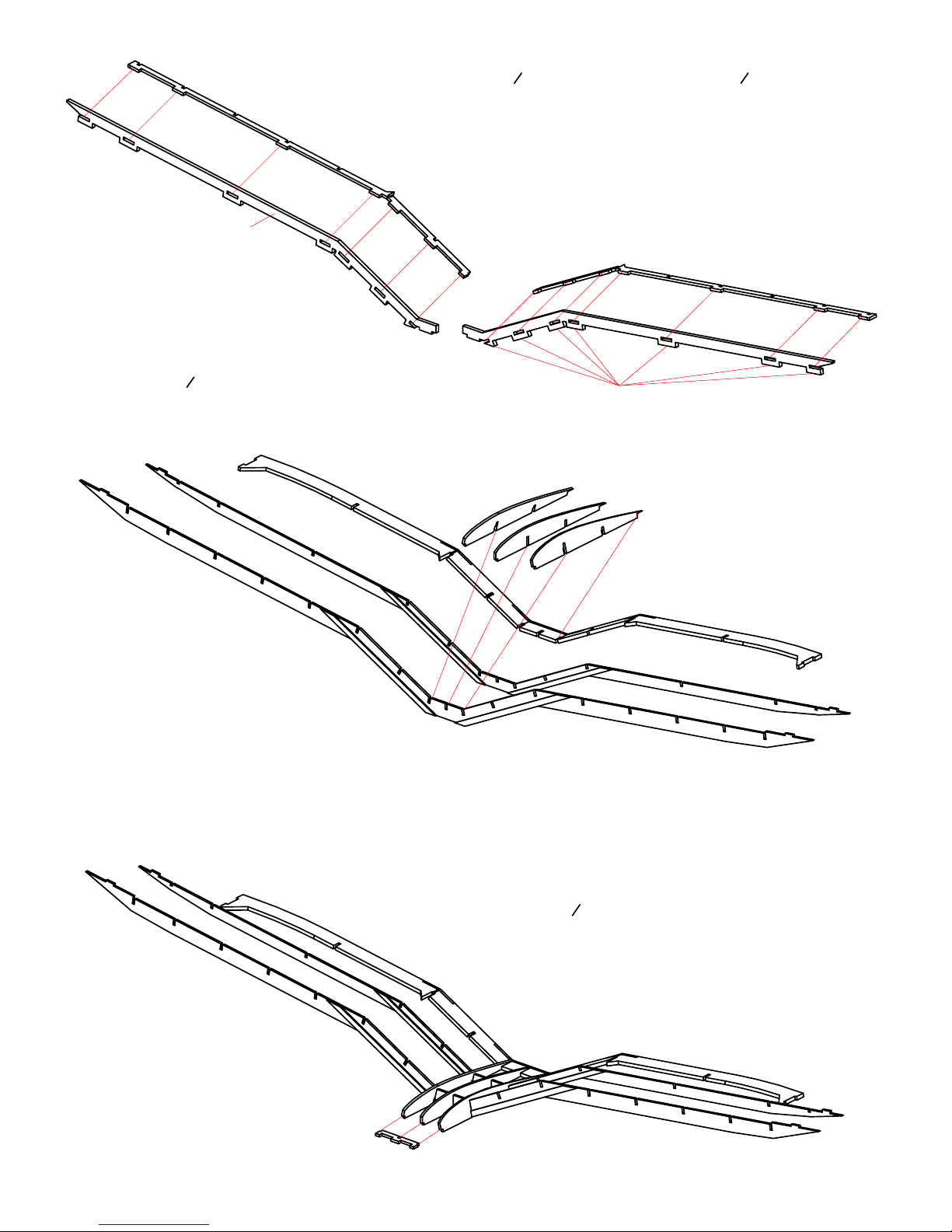
10. Press the
edge W11 parts, as shown. Secure with thin CA, making sure the
1
" balsa W4 and W5 parts into the
16
3
" balsa leading
32
parts are fully inserted and at a right angle to each other.
11. Trim off the bottom "tabs" on W11, so the bottom surface is
smooth.
W11
12. Slide the
into the trailing edge assembly. Tack glue with thin CA,
1
" balsa W12 and W13 ribs onto the spars and
16
making sure everything is fully inserted and aligned.
W4
W4
W5
Trim off tabs,
after assembly.
W13
W12
W13
W3
13. Slide the
aligned and tack glue with thin CA.
1
" balsa W3 onto ribs. Make sure it is fully
16
Page 8
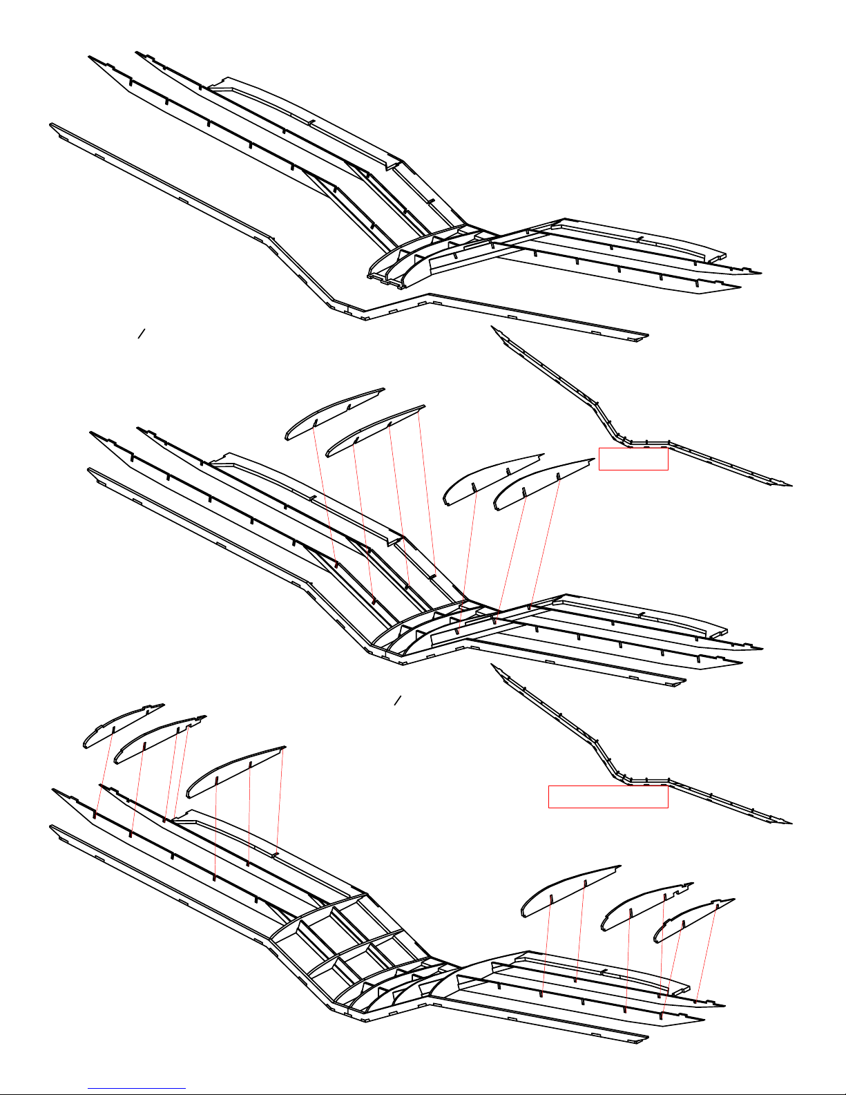
14. Slide the leading edge assembly onto W3. Make sure
everything is aligned and tack glue it with thin CA.
15. Slide the
LEFT wing. With the outer wing panel hanging off the
1
" balsa W14 and W15 ribs in place on the
16
table, tack glue them with thin CA, making SURE that
they are fully inserted into the spars, trailing edge, and
leading edge assembly.
W15
16. Repeat step 15 for the RIGHT side of the
wing.
W18
W17
17. Slide the
W16
W14
W14
1
" balsa W16, W17,
and W18 ribs onto the RIGHT
16
side of the wing assembly, being
careful with W18. Lay the outer
panel FLAT on the table, with the
rest of it hanging off the table,
and tack glue the ribs in place,
with thin CA. MAKE SURE that
the ribs are fully inserted and
aligned BEFORE using glue.
TABLE
W15
TABLE
18. Repeat step 17 for the LEFT side
of the wing.
W16
W17
W18
Page 9

W20
W19
19. Slide the
thin CA after making sure they are FULLY pressed into place.
1
" balsa W19 and W20 ribs in place and tack glue with
16
W19
W20
20. Glue the W23 wing tip parts together, using thin CA.
21. Assemble the W23 wing tips onto the wing, being careful with
the last rib. Start at the leading edge and pressing them in place.
After you are sure they fit properly, secure them in place with
thin CA.
22. Reinforce all joints in the wing with several drops of thin CA.
23. Sand the leading edge to the shape shown on the plans and
lightly sand the entire wing. You can use painters tape over the
ribs when sanding the leading edge, to protect them from
damage when sanding.
Page 10
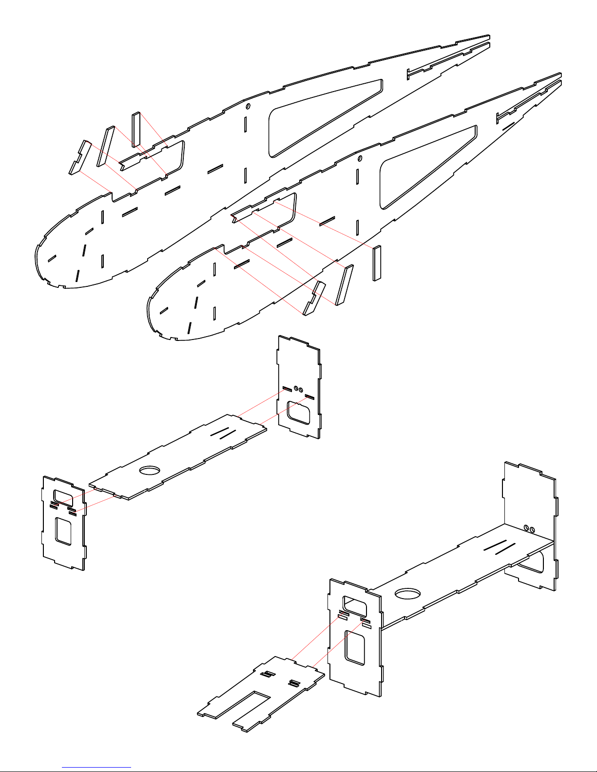
24. Glue in the W19, W20, and W21 parts
into the fuselage sides, using thin CA.
F19
F20
F21
F21
F20
F19
F3
25. Press the F1 crutch into the F2 and F3
formers. Do NOT glue them yet.
F1
F2
26. Press the plywood F4 motor mount
into the F2 former, but do NOT glue it
yet. MAKE SURE you install it with
RIGHT THRUST (Engraved text facing
UP), as shown on the plans. If you glue
it in upside down, your plane will NOT
fly properly!!!
F4
Page 11
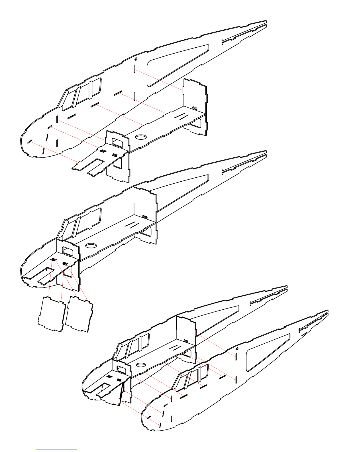
27. Press the crutch assembly into the
right fuselge side. Do NOT glue it.
F6
28. Press the plywood F6 and F7 landing
gear formers into the crutch and
fuselage side. Do NOT glue anything
yet.
F7
29. Press the crutch/fuselage assembly
into the left fuselage side. Make sure
everything is fully pressed together
and the fuselage is square. Secure the
joints with thin CA.
Page 12
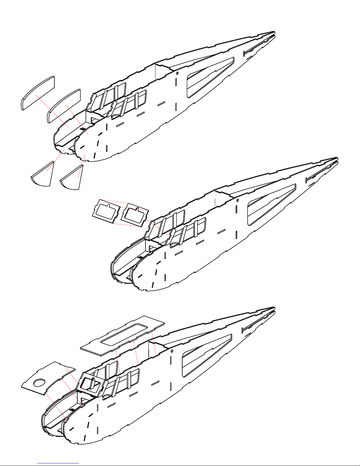
30. Glue in the F22 and F23 doublers on
the INSIDE of the fuselage front, as
shown, using thick CA.
F22
F22
F23
F23
F24
F10
F10b
31. Glue together the balsa F10 and
plywood F10b, using thick CA, MAKING
SURE that they are aligned with each
other. Cut out the middle of F10 by
trimming the uncut engraved lines on
the part.
32. Press the F10 part into the fuselage,
as shown. Secure in place with thin CA.
F9
33. Press F24 in place and secure with
thin CA.
34. Glue F9 in place on the fuselage front,
as shown.
Page 13
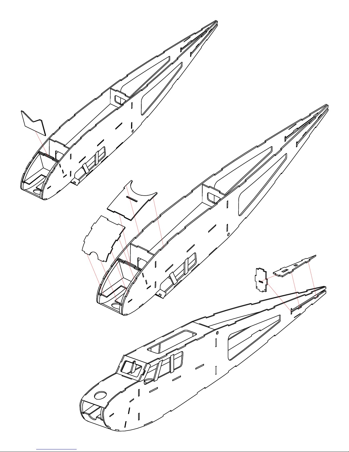
35. Press the plywood F17 in place, as
shown. Make sure it is fully pressed in
place and secure it with thin CA.
F17
36. Glue F11 and F12 in place on the
fuselage, as shown.
F11
F12
F14
F13
37. Press F14 into F13, but Do NOT glue
them together yet.
38. Press the F13/F14 in place in the
fuselage, as shown above, and on the
plans. MAKE SURE the rear of the
fuselage sides are lined up, and glue
the F13/F14 parts in place, with thin
CA.
Page 14
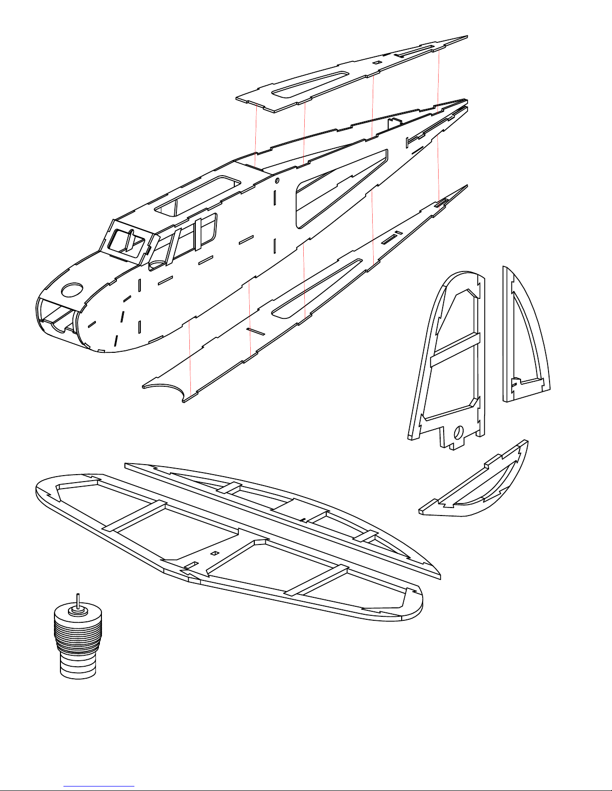
39. Press F15 in place and glue with thin
CA, AFTER making sure it is fully
inserted in the fuselage sides.
40. Press F16 in place and glue with thin
CA AFTER making sure it is fully
inserted in the fuselage sides.
F15
F16
41. Glue the horizontal stab, elevator,
vertical fin, rudder, and skid with thin
CA.
42. Assemble the dummy engine, as shown on the plans, using thick CA to glue the parts together.
43. Sand the entire airframe, rounding corners of the front of the fuselage, and finishing the airframe with
320 grit sandpaper.
44. Bevel the elevator and rudder, as shown on the plans.
45. Paint the dummy engine, as desired.
46. Cover the airframe with So-Lite or tissue. Do NOT use heavier coverings such as MonoKote, UltraCote,
UltraCote Light, Solarfilm, or the cheap Chinese coverings. Heavier coverings will warp the structure
and be WAY too heavy for this lightweight plane.
Page 15
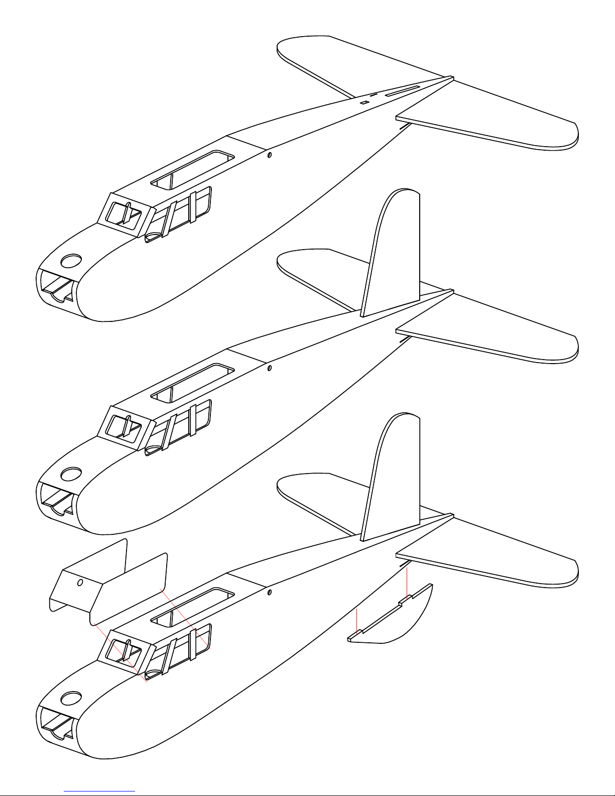
47. Insert the horizontal stab through the slot in the
fuselage, but do NOT glue it in place yet.
48. Insert the vertical fin through the slot that goes through
the fuselage top, through the stab, and into the stab
support in the fuselage. Move the stab slightly to get
evrything aligned and pressed in place.
49. MAKE SURE that the stab is paralell to
the fuselage and that the vertical fin is
at a 90 degree angle to the horizontal
stab. Secure the parts with several
small drops of thin CA.
50. Glue the skid in place with thick CA, making SURE
that it is at a 90 degree angle to the bottom of the
fuselage.
51. Fold the windshield along the dashed cut lines, and
glue it onto the fuselage, using several SMALL drops
of thick CA on the fuselage sides.
Page 16
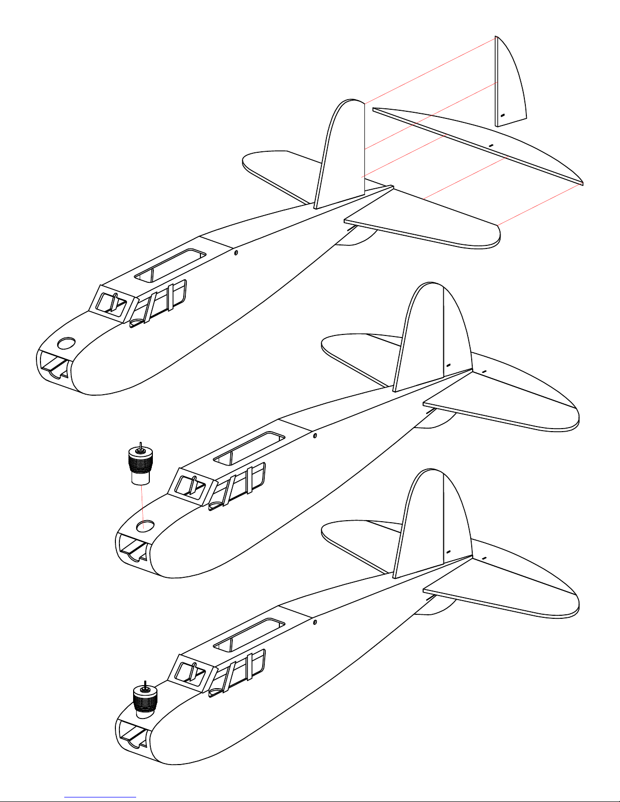
52. Hinge the elevator to the horizontal stab, using
hinge tape, as shown on the plans. There should be
a small (1/64") gap between the parts. Do the same
for the rudder and vertical fin.
53. Insert the motor through the hole in the fuselage
top front. It should go through the hole by about
1/8". Secure it in place with several small drops of
thin CA.
Page 17
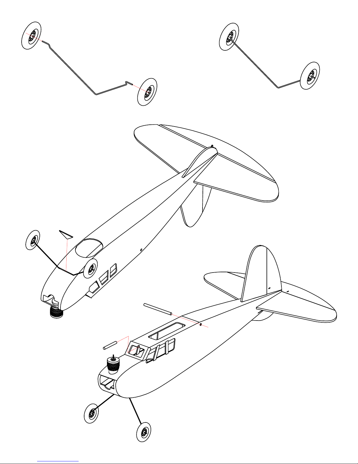
54. Bend and cut the landing gear
55. Secure the wheels to the landing
56. Press the landing gear into the
slot on the fuselage bottom. Press
in the landing gear retaining part,
F18. You can use thin CA to glue in
the retainer, if you do not want to
remove the landing gear later on.
wire, as shown on the plans.
gear, as shown on the plans.
F4
57. Cut and install the wing retaining
dowels, as shown on the plans.
Page 18
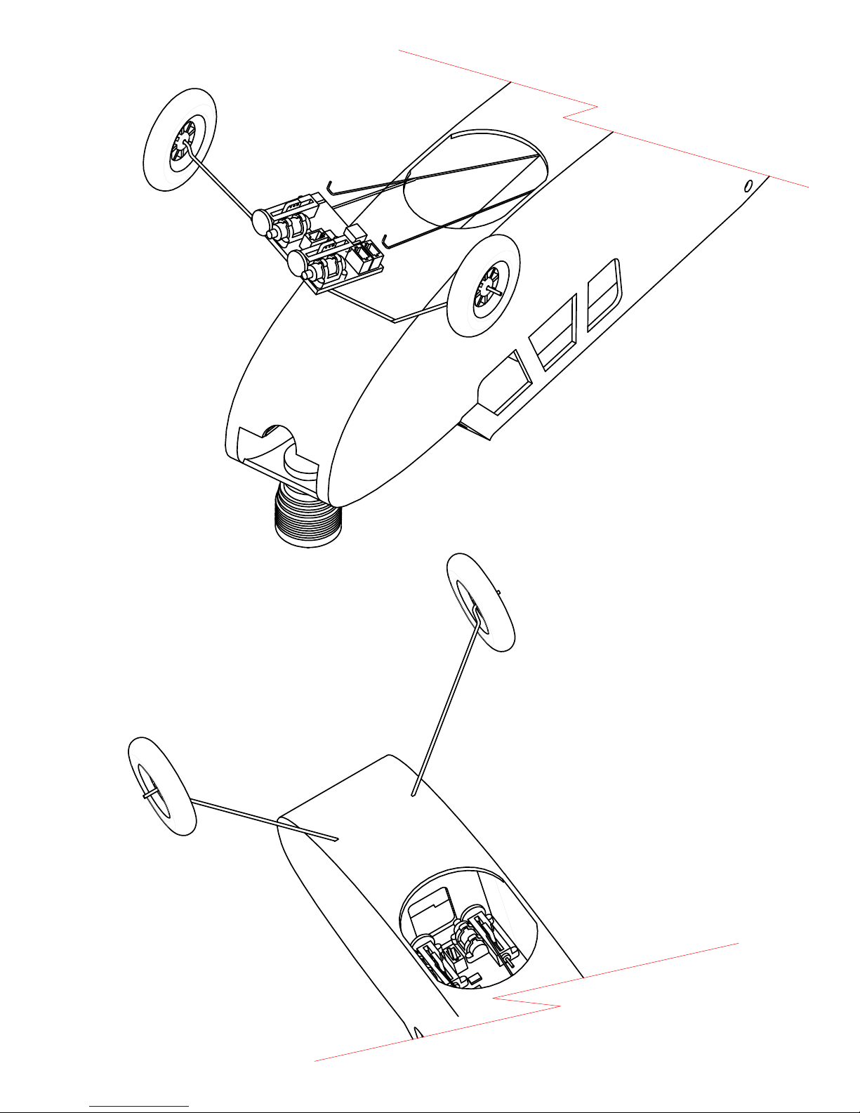
58. Install the pushrods and reciever,
as described on the plans, in the
location shown on the plans.
Page 19
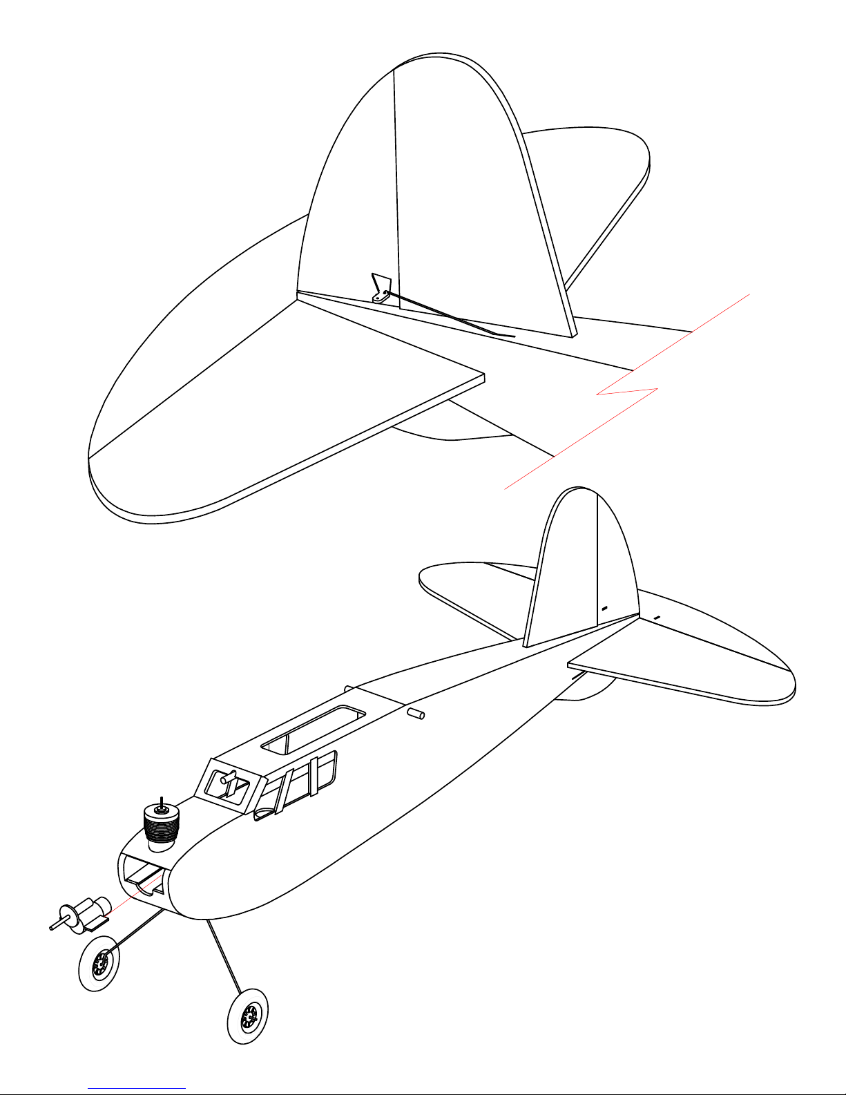
59. Glue the plywood control horns into the
rudder and elevator with thick CA, as
shown here and on the plans.
60. Follow the directions on page 2 of the
plans to create and install the Z-Bend ends
on the pushrods.
61. Trim the mounting "posts" off the gearbox
and glue the motor/gearbox in place, using
a couple drops of thick CA. The motor will
have slight RIGHT thrust, once installed.
Page 20
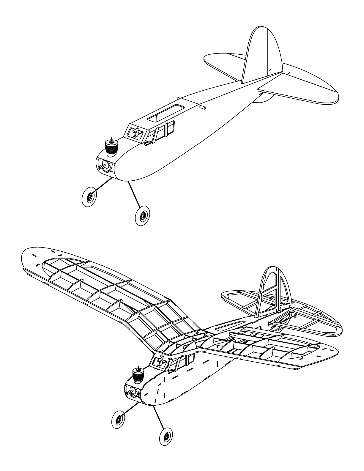
62. Hook up your motor wires to the RX,
secure the battery to a fuselage side with
Velcro, mount the wing with 4 rubber
bands, and balance the model where it is
shown on the plans.
63. DOUBLE CHECK your wings for any warps.
If the wing is warped, straighten it out
BEFORE trying to fly your model.
64. Use about 1/2 throttle and a gently hand
launch for your first flight. Trim it out, if
needed, and enjoy your SpookE Micro!
 Loading...