

Mountain Models P-51 Mustang Assembly Manual
1
www.MountainModels.com
P-51 Mustang
1/12 Scale Electric Park Flyer
Wingspan: 37”, Wing Area: 254 sq. in., Weight: 15 to 19.5 oz
LIABILITY RELEASE
In that Mountain Models has no control over the final assembly or material used for final assembly, no
liability shall be assumed or accepted for any damage resulting from the use by the user of the final
user-assembled product. By the act of using the user-assembled product, the user accepts all resulting
liability. If the buyer is not prepared to accept the liability associated with the use of this product, the
buyer is advised to return the kit immediately in new and unused condition.
THIS PRODUCT IS NOT INTENDED FOR CHILDREN 12 YEARS OF AGE OR YOUNGER
Warning: This product may contain chemicals known to the State of California to cause cancer or birth
defects or other reproductive harm
Instructions Version 1.61, July 27, 2011
Copyright 2005-2011 Mountain Models

Kit Contents:
1. CAD Plan Sheet
2. Instruction Manual
3. Laser Cut Balsa and Plywood Sheets (Bagged)
4. Vac-Formed Plastic Parts
• Clear Canopy
• Cockpit with Seat
• Cowling
• Exhaust Stacks (Left and Right)
• Radiator Scoop (Top and Bottom)
5. Large Hardware Bag
• 2 ea. 1-3/4” DuBro Wheels
• 2 ea. Main Gear Wire (3/32” Dia. x 7”)
• Pushrod Wire (0.047” Dia. x 18”)
• Velcro Set, 4” (Loop and Pile)
• Velcro, Double Sided, 8”
• Thin Plastic Tube
6. Small Hardware Bag
• 2 ea. Landing Gear Wheel Bushings (Aluminum Tube)
• 2 ea. Fixed Gear Wheel Keepers (Star Locks)
• 2 ea. Retract Gear Wheel Keepers (Plastic Tube)
• 2 ea. 4-40 T-Nuts
• 2 ea. 4-40 x 1” Nylon Bolts
• ½” Tail Wheel
• Rare Earth Magnet
• 3/8” Dia. Steel Washer
• E-Z Hinge Material
• Screws, Gear Mount (8)
7. Pull-Pull Parts Bag
• 6 ea. Micro Servo Connector
• 6 ea. Servo Connector Backer
• 6 ea. Servo Connector Lock Screw
• 4 ea. Cotter Pin
• 8 ft. Pull-Pull Line
8. Decal Bag
• 2 ea. Stars and Bars for Fuselage Sides
• 2 ea. Stars and Bars for Wings
Recommended Items for Finishing:
1. 1 Roll Lightweight Covering (So-Lite or Similar)
2. Extra Covering or Trim Sheets for Details as Needed
3. Paint for Finishing Plastic Parts
4. GWS 50mm 2 or 4 Blade Spinner (or Similar)
5. Optional: GWS “Blue” Retracts
Suggested Electronics:
1. 4 Channel Transmitter Minimum (5 minimum for retracts)
2. 4 ea. Sub Micro Servos (HS-55, GWS Naro, or equivalent)
3. Optional: HS-55 (or similar in size and torque for retracts)
4. Y-Splitter for Aileron Servos (or 6ch RX with appropriate transmitter)
5. Optional: 2 ea. 6” Servo Extensions (if using servos with short wires)
6. Micro Receiver, (4 channel minimum, 5 channel minimum for retracts)
2
Copyright 2005-2011 Mountain Models

3
Brushed Power System:
1. GWS EPS350C-DS Motor/Gear Box
2. Micro Electronic Speed Control (10A Minimum)
3. GWS 10x8 (2-Blade or 4-Blade) Propeller
4. 8-Cell, 650 mAh NiMH Battery
Brushless Power System:
1. Himax 2015-4100 Brushless Motor, GWS Gearbox (“D”, 6.6:1) or Himax Gearbox (Recommended), 10x8 4-blade propeller, and a
3S LiPo battery.
2. Himax 2015-4100 Brushless Motor, GWS Gearbox (“C”, 5.53:1) or Himax Gearbox (Recommended), 10x8 2-blade propeller, and
a 3S LiPo battery.
3. Himax 2015-5400 Brushless Motor, GWS Gearbox (“C”, 5.53:1) or Himax Gearbox (Recommended), 9x7 2-blade propeller with
3S LiPo or 10x8 4-blade propeller with 2S LiPo battery.
4. Himax 2015-5400 Brushless Motor, GWS Gearbox (“D”, 6.6:1) or Himax Gearbox (Recommended), 9x7 or 10x8 2-blade
propeller, and 3S LiPo battery.
Other Items That You Should Have:
1. CA (Super Glue, thin and thick)
2. Plastic Wrap or Wax Paper
3. X-Acto Knife and Blades
GENERAL INFORMATION:
Thank you for purchasing the Mountain Models 1/12 Scale P-51 Mustang Electric Park Flyer. We believe this model fits an area that has
been largely ignored or done poorly to date. We strived to provide a laser cut kit that provides the builder a properly engineered, nicely
finished, lightweight, great flying park flyer that is as scale as possible.
Designed in 3D CAD, we used interlocking laser cut parts throughout, to make assembly as easy as possible, locking parts together for proper
alignment and fit. This kit is designed for the novice to intermediate builder and the somewhat experienced pilot in mind.
You should have some experience with tail draggers, knowing how to use the rudder and elevator on takeoff runs. Once in the air, however,
even the novice can fly this model. If you don’t have tail dragger experience, get some help from someone that does and you’ll be fine flying
this model. You’ll be the envy of pilots at your field when you show up with this model. They won’t believe what they’re seeing!
Please let us know about your experiences building and flying this model. We look forward to customer feedback and want to know how
you’re doing with it!
Thank you,
Brian Eberwein
info@MountainModels.com
Mountain Models
2935 N Lynndale Drive
Appleton, WI 54914
1. READ THE INSTRUCTIONS all the way through and study the plans BEFORE starting any work on this model!
2. Make sure you completed the above. Yes, this is important enough to state twice.
3. Tape the plans to your nice clean work surface and cover it with plastic wrap or wax paper. You do want to keep your work surface
clean and not glue your parts to the plans, right?
4. DO NOT REMOVE ANY PART FROM THE SHEETS UNTIL YOU NEED THEM. Some of the parts are delicate and you do
NOT want them laying around getting damaged before you need them.
5. DO NOT FORCE the fit of any part. If the fight seems too tight, stop, make sure you have the right part and it’s going in the right
way. If it’s still too tight, lightly sand the part so it fits.
6. DO NOT GLUE ANYTHING until you are told to do so. If you glue something before you are told, there is a chance that parts
after it may not be able to be assembled without modification or breakage.
7. Make solid glue joints. You will be tack gluing in some steps and reinforcing those joints later on. Make sure to reinforce the joints
when told, so you end up with a nice strong airframe.
ASSEMBLY ADVICE:
Copyright 2005-2011 Mountain Models

FUSELAGE ASSEMBLY:
1. Remove the fuselage side parts from the 1/8” Balsa sheet. They are all on the same sheet. Match up all of the side pieces and make
sure you have 2 of each one. If you only have one of a part, double check the sheet and find it. The first side you will be assembling
is the LEFT side over the plans, with the text facing up. (This way, the text will be on the inside when you assemble the fuselage.
Assemble the parts over the plan sheet as shown in the image below. If a part seems tight, double check and make sure you have
the right one and it is oriented correctly. If, after double checking it is too tight, then lightly sand the mating surfaces until it fits
nicely. Secure all joints with thin CA. Lay wax paper or plastic wrap over the completed left side and assemble the right side parts
over it. Secure all joints with thin CA.
4
2. Remove the 3/32” Balsa F6 part from the sheet. Get the rare earth magnet from the bag. Turn F6 so the text is facing the work
surface. Press the magnet into the hole as shown in the image below. Use thin CA to secure the magnet in place.
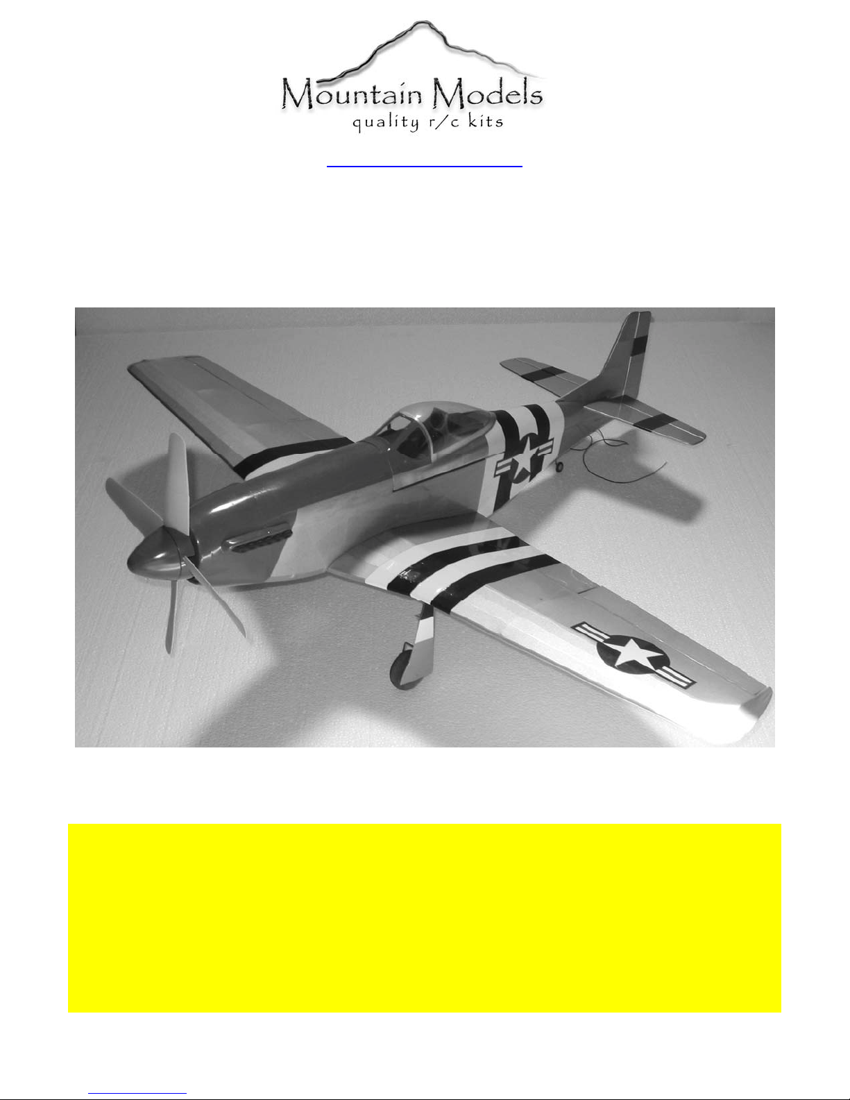
3. Assemble the parts to make complete 1/8” F2, 1/16” F10, and 1/8” F7 formers over the plans. AFTER the parts are aligned
properly, secure with thin CA. make sure you get a good glue bond with the parts.
4. Remove the 1/8” Balsa F-28 parts from the sheet. Remove the 4-40 T-Nuts from the parts bag. Set the F-28 parts on the work
surface with the text facing up. Press the T-nuts into the holes in the parts, making sure they are in as far as they can go. Secure the
nuts around the outside using thin CA. Be careful not to get glue n the threads.
Copyright 2005-2011 Mountain Models
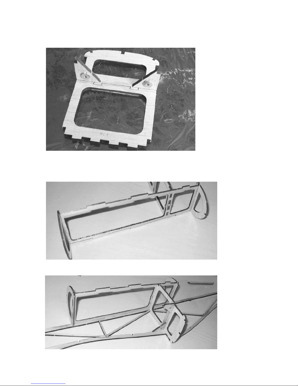
5. Push the F28 parts into the completed F7 former as shown in the image below. Make SURE that the formers are positioned like
they are in the image and the blind nuts are facing the right direction, otherwise, they won’t do their job of keeping the wing in
place! After you have double checked that they are correct, make sure they are at a 90 degree angle to F7, and secure them with
thin CA.
5
6. Press the F7 assembly from the last step into the F6 as shown in the image below, with side flush with the magnet facing away
from F7. Make sure that the triangular F28 parts are facing to the long end of F6 as shown. After you double check that they are
oriented properly, make sure they are at a 90 degree angle to each other and secure with thin CA.
7. Press the 3/32” F5A and F8 parts onto the ends of F6, making sure they are on the correct ends. After everything lines up properly,
make sure the formers are 90 degrees to F6 and secure with thin CA.
8. Do not glue anything until you are told to do so. Take the assembly from the previous step and carefully press it into place on the
fuselage RIGHT side as shown in the image below. DO NOT GLUE ANYTHING at this time.
Copyright 2005-2011 Mountain Models
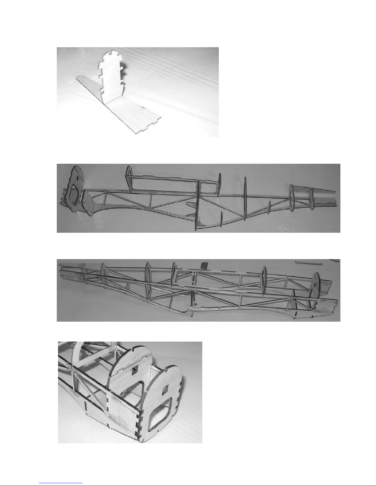
9. Place the 1/16” F15 former flat on your work surface. Press the 1/16” F13 into place as shown in the image below. Make sure they
are at 90 degrees to each other and secure with thin CA.
6
10. Do not glue anything until you are told to do so. Press the 1/8” F2 assemble into the fuselage RIGHT, making sure the text is facing
FORWARD. THIS IS IMPORTANT. Press the 1/16” F9, 1/16” F10, 1/16” F11, 1/16” F12, and 1/16” F13 into place but DO NOT
glue them yet. Press the assembled F14/F15 piece into place as shown in the image below. DO NOT GLUE ANYTHING YET.
11. Assemble the fuselage LEFT to the assembly from step 10. DO NOT GLUE anything yet. Be careful and make sure all tabs are
fully pressed in/together and that everything is aligned properly. See the image below for what it will look like when you are done.
Be gentle when pressing the side onto the formers. If something is tight, use light sandpaper on the joint.
12. Assemble 1/8” Balsa F1 to the fuselage assembly, making sure the text is facing FORWARD. This is IMPORTANT! Do NOT glue
it in yet. Use low-tac tape to hold it in place if you need.
Copyright 2005-2011 Mountain Models

13. Press the 1/8” F27 piece into place on the bottom front center of the fuselage as shown in the image below, but do NOT glue it yet.
Make sure it is facing the right direction. Press the 3/32” F30 parts into place on the bottom front as shown in the image below, but
do NOT glue it yet.
7
14. Press the 1/8” F24 piece into place on the fuselage front top as shown in the image below, but do NOT glue it yet.
15. Press the 1/8” F25 piece into place on the fuselage rear top as shown in the image below, but do NOT glue it yet.
16. Be gentle with the stringers in the next step, as they can break if you are not careful with them. If they don’t seem to fit, please
check to make sure they are oriented correctly, and if they are still tight, lightly sand the mating surfaces until they fit nicely. Press
the 1/8” F26 piece into place on the fuselage rear bottom center as shown in the image below, but do NOT glue it yet. Press the two
(2) 3/32” F29 pieces into place on the fuselage rear bottom, between F7 and F11 as shown below, but do NOT glue them yet. Press
the two (2) 3/32” F321 pieces into place on the fuselage rear bottom, between formers F11 and F14 as shown in the image below,
but do NOT glue them yet.
Copyright 2005-2011 Mountain Models

17. Install the 1/8” F5B and 1/8’ F32 parts in the fuselage as shown in the image below, but do NOT glue them in yet.
8
18. Double check and make sure that all parts are tabbed together and seated fully. Okay, the moment you’ve been waiting for, grab
your thin CA bottle and get ready to glue! Place the fuselage over the plans to make sure it is straight and untwisted. Start with the
fuselage where F6 tabs into the sides, and apply thin CA to the joints, making sure the parts are fully seated. Secure F7 to the
fuselage sides with thin CA. From F7, work your way forward, making sure all parts are pressed together and secure the formers to
the sides with thin CA. After that is done, start at F7 and work your way to the back end, securing all of the formers to the fuselage
sides with thin CA. Make sure to keep an eye on the fuselage and ensure that it is straight and not twisted along the way. After the
formers are glued, go ahead and secure the stringers with thin CA. Your fuselage should be glued together now. Make sure you do
not forget any joints!
19. Find the 1/8” S12 piece and set it next to your fuselage. Apply thick CA to the S12 part and assemble it to the fuselage as shown in
the image below. Make sure it is aligned with the F-15 part and pressed against the rear former.
20. Take out the 24” long 1/32” balsa sheet and remove the 4 parts. Place them on your protected work surface, and using thick CA,
glue them together as shown in the image below. Make sure you have a good glue joint between the parts.
Copyright 2005-2011 Mountain Models
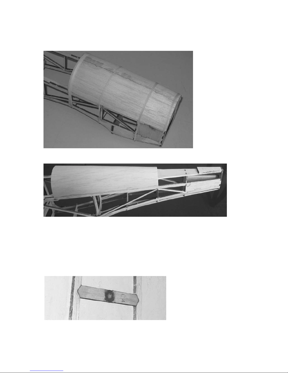
21. The larger of the 2 parts is the front sheeting and the other is the rear. Wet the front 1/32” sheet part with water on the side with the
engraved lines. This will make it easier to conform to the fuselage. Place it on the fuselage with the engraved line on the inside.
The lines are to help you position it. There will be a little hanging off the front, back, or both. This is okay as it will be trimmed
later. There may also be a little extra on the outside edges. This is also okay as we will trim it later. Hold the piece in place with
rubber bands until it dries completely. Check it every so often to make sure it hasn’t shifted.
9
22. Repeat the previous step for the rear sheet, but make sure that the back end of the sheet is lined up to the rear edge of F12. After
both sheets have dried completely, carry on to the next step.
23. Making sure that the front sheeting has not moved and is still properly aligned, turn the fuselage over and secure the 1/32” sheet to
the center 1/8” spine. Start gluing the sheet to the formers, pressing down to make sure it is in contact with all of the formers. Do
not glue all the way to the outside edges yet. There may or may not be a slight overhang of the sheeting before trimming. The parts
are cut slightly oversize to account for different sheets shrinking differently when wetted. Repeat this for the rear sheeting. Use a
sharp X-Acto knife or sandpaper to CAREFULLY trim the sheeting to sit flush with the fuselage sides. After the sheeting lies
down flush with the sides, go ahead and glue it down to the last part of the former and fuselage sides. There may or may not be a
slight overhang of the sheeting before trimming. The parts are cut slightly oversize to account for different sheets shrinking
differently when wetted. Repeat this for the rear sheeting. Take your time and be careful not to remove too much at a time.
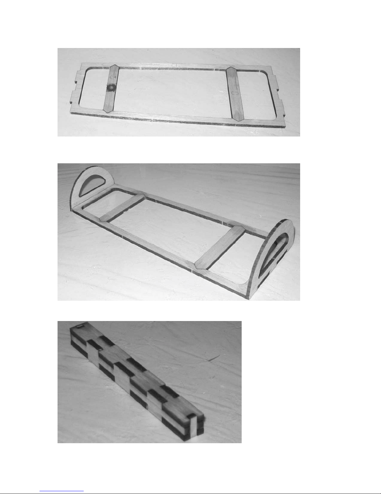
24. Locate and remove the 1/8” C4 part from the sheet. Locate the steel washer from the parts bag. Use the engraved lines and sand
between the engraved lines, down until the washer sits flush with the top surface of the C4 part. Remove a little material at a time
to make sure you do not remove too much material.
Copyright 2005-2011 Mountain Models
10
25. Locate and remove the C1 and C5 parts from the 1/8” balsa sheet. Assemble them your work surface, making sure they are flat and
secure the joints with thin CA. Make sure the joint between C1 and C4 is glued well.
26. Locate and remove C2 and C3 from the 3/32” balsa sheet. Place the assembly from the previous step with the washer DOWN.
Place the 3/32” balsa formers in position and secure the joints with thin CA, making sure they are at 90 degrees to the C1 part.
MAKE SURE you glue them as shown in the image below, so the magnet will hold the canopy down!
27. Remove the motor stick parts from the 1/8” plywood sheet. Assemble it as shown in the image below. Be sure to make good glue
joints!
28. Set the fuselage, motor stick, and canopy frame aside in a safe place where it will not get damaged and continue onto the next
section.
Copyright 2005-2011 Mountain Models
 Loading...