

J-3 Cub
Fuselage Kit
J-3 Cub Specifications
Wingspan: 48 in.
Length: 30 in.
Wing Area: 332 sq. in. (Standard Wing)
Weight (Ready to Fly): 13.4 - 17 oz. (Depends on motor & battery)
Wing Loading: 5.8 – 7.6 oz. / sq. ft. (Standard Wing)
Revision History
Date Revision Notes/Comments
11/28/2006 1.0 Document initial release.
Thank you for purchasing the Mountain Models 1/9 Scale J-3 Cub. This plane is a scale
aileron/elevator/rudder (full house) setup, designed for the low experience pilot on up who
wants a super easy flying scale plane.
If you have not flown ailerons before, this plane could make a great aileron trainer for you. If
you have no tail dragger experience, this plane also makes a great first tail dragger.
We HIGHLY recommend resisting the temptation to overpower the model. In the thin air at
6000’ where it was designed, it flies beautifully and has plenty of extra power, even with the
cheap 80 watt brushless out-runner motors.
Please let us know you experiences building and flying this model. We look forward to customer
feedback and want to know how you’re doing with our products!
Thank you,
Brian Eberwein
Mountain Models
PO Box 6815
Colorado Springs, CO 80934
www.mountainmodels.com
Phone: 719.630.3186
Before You Begin
Check to make sure that all of your parts are there and in good shape.
Parts List
Number
in Kit
Bundled Parts
1 1/8” Lt. Ply Sheet
1 1/16” Ply Sheet
1 1/32” Ply Sheet
3 1/8” Balsa Sheets
4 3/32” Balsa Sheets
1 1/16” Balsa Sheet
1 1/32” Balsa Sheet
2 1/8” Balsa Sticks
2 Pushrod Housings x 18”
1 Windows (2 Sides, 1 Front)
1 Plan Sheet
1 These instructions of course!
Metal
4 1/16” x 12” Wire
2 0.032” x 18” Wire
1 0.039” x 9” Wire
Plastic
1 1 ea. Cowling and 2 ea. Engine Parts
Description of Part
2

Number
in Kit
Bagged Parts
1 1/16” x 3/4” x 5.75” Ply Battery Stick
1 1/4” Balsa Sheet
1 3/16” Balsa Sheet
1 1/8” x 4.25” Dowel
2 Micro EZ Servo Connector
2 DuBro Micro EZ Link
5 4-40 T-Nut
2 4-40 x 1” Nylon Bolt
2 2” DuBro Wheels
1 3/4” DuBro Tail Wheel
1 #2 Motor Screw
4 Cowling Screws
2 Magnets
2 #4 Washer (Magnetic)
5 #4 Washer (Non-Magnetic)
2 EZ Hinges
2 3/32” x 3/4” Aluminum Tube (Wheel Bushings)
2 1/8” x 5/8” Aluminum Tube (Wheel Bushings)
3 4-40 x 3/8” Socket Cap Screw
1 Allen Wrench, 3/32”
2 Wheel Retainers
1 1/2” Double Sided Velcro
1 3/4” Sticky Backed Velcro (Pile and Loop Sides)
1 Spider Wire, 12 feet
Description of Part
Building Materials You Will Need
• Smooth and flat work surface
• Wax paper or clear plastic wrap to protect the work surface
• Thin and thick Cyanoacrylate (CA) glue
• 5 Minute Epoxy
• Hobby knife with #11 blades
• Needle nose pliers
• Wire bender or pliers for bending landing gear wire
• Wire cutters
• Screwdrivers
• Sanding block, 320 to 400 grit sandpaper
Finishing Materials You Will Need
• Covering material (So-Lite or similar)
• Sealing iron for applying the covering
• Paint for cowling and engine plastics
3

Electronics You Will Need
• 4 channel radio minimum
• 4 channel receiver minimum
• 2 ea. aileron servos (we recommend either the GWS Picos or Naros)
• 2 ea. tail servos (we recommend the Hitec HS55s, or GWS Picos/Naros)
• 2 ea. 12” servo wire extensions
• 1 ea. Y-Connector for ailerons (or 5+ channel RX with 2 aileron servo mixing on TX)
• Brushless Motor of 80 to 100 watts or Geared brushed GWS350C motor
• Electronic Speed Control
• 2 cell 1200 mAh LiPo pack
General Building Tips
• READ THE INSTRUCTIONS all the way through and study the plans BEFORE starting any
work on the model.
• Tape the plans to your nice clean work surface and cover it with wax paper or plastic wrap.
You want to keep your work surface clean and not glue the parts to the plans, right?
• Balsa is a lightweight and fragile wood, so you do need to be careful with it; however, you
will also need to use a little bit of force to make everything fit properly, so don’t be too
timid.
• Do not remove any pieces from the balsa sheets until they’re ready to be used. That way,
parts won’t get mixed up or disappear.
• Do NOT glue anything until told to do so.
• Join all of your pieces using thin CA (Cyanoacrylate) glue, unless we tell you otherwise. In
general, only a small amount of CA is necessary to glue parts together.
• Don’t over force your pieces together. If they aren’t fitting together properly, make sure you
have the right pieces and that they are oriented correctly. If needed, you can lightly sand
the part to fit after making sure it is the correct part and oriented correctly.
• If you want to remove the charred edges caused by the laser cutting process, lightly
dampen a cloth with bleach and gently rub the affected areas. Removing the char will not
increase the strength but will make it look better. It also keeps that dark edge from showing
under the lightweight coverings.
Assembly Instructions
against the normal building conventions. We have found that fewer pieces get mangled this
way, since you are building the stronger pieces first. For example, the tail feathers are at the
end of the building process instead of the beginning, so that they are less likely to get damaged
and are being built right before they are attached to the fuselage and each other.
Experienced builders may notice that this building order goes
4
Step 1: Assembling the Fuselage
The first thing you are going to assemble is the fuselage of your airplane. This involves
assembling the fuselage sides, formers, stringers, firewall, etc.
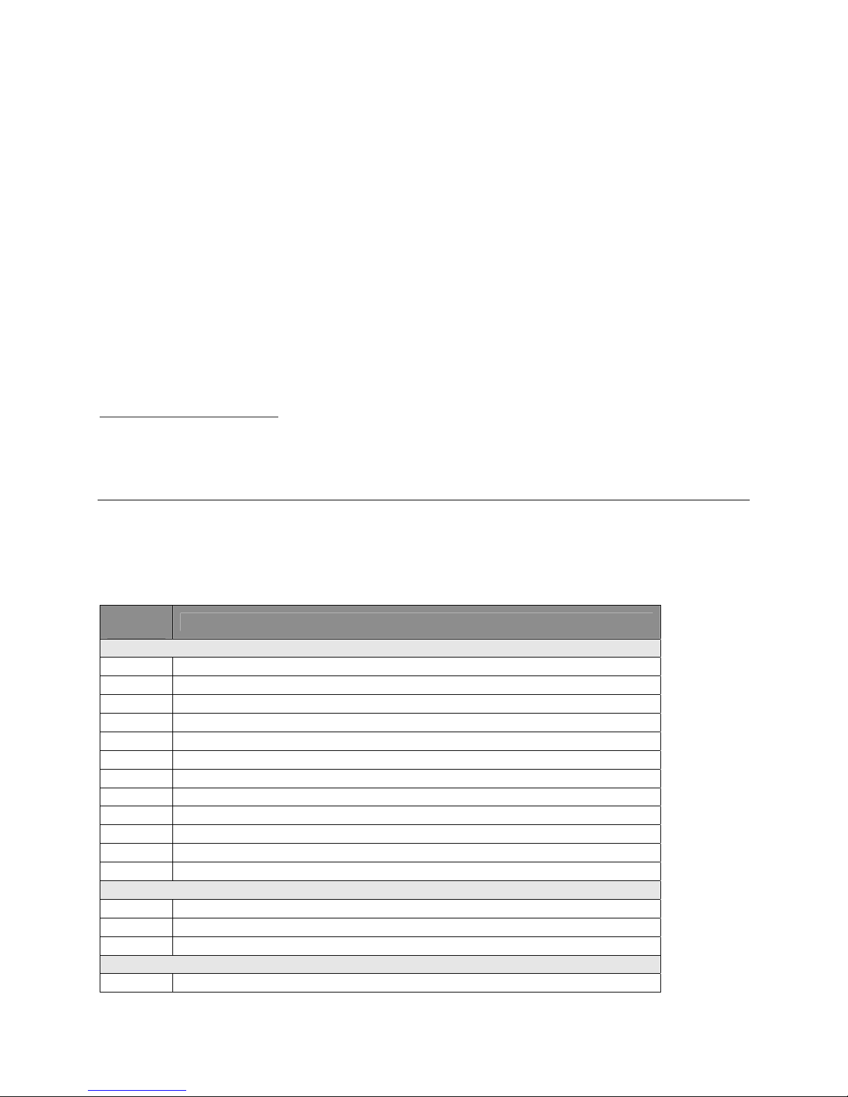
1. Glue the 3/32” balsa fuselage side parts together with thin CA. Ensure that they are seated
properly with no gaps.
To remove the pieces, gently flex the balsa sheets until the pieces fall out.
You may find that you need to carefully trim the extra pieces of wood that
originally held the piece to the sheet. You can also use a #11 X-Acto blade to
trim them out of the sheets.
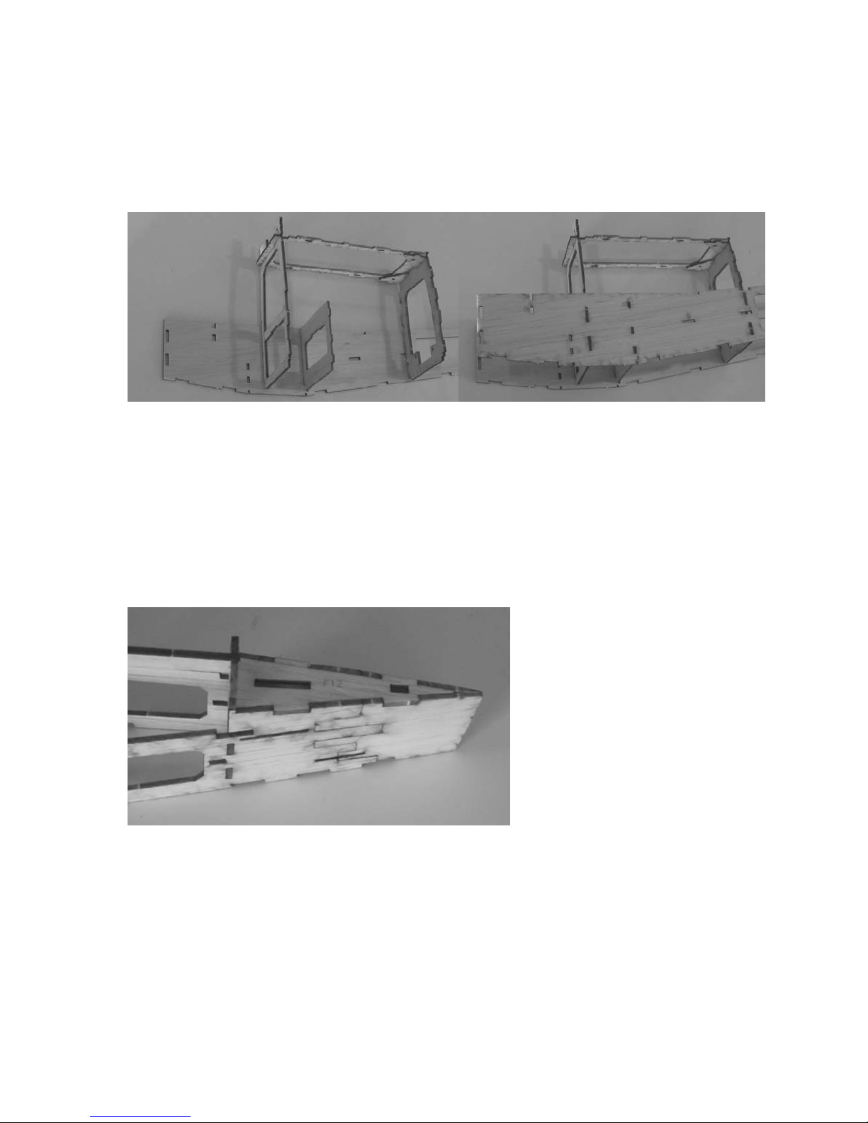
2. Glue the 3/32” balsa reinforcement piece F9A to F9 and F10A to F10 with the engraved text
forward on both parts. Make sure the parts are flush with the bottom and lower sides of the
parts as shown in the left image below.
3. Press the 3/32” balsa part C8 into the 1/8” balsa part F8. The text on F8 should be facing
TOWARDS C8 and the text on C8 should be facing UP. Reference the above right image. Do
NOT glue the parts together yet.
5
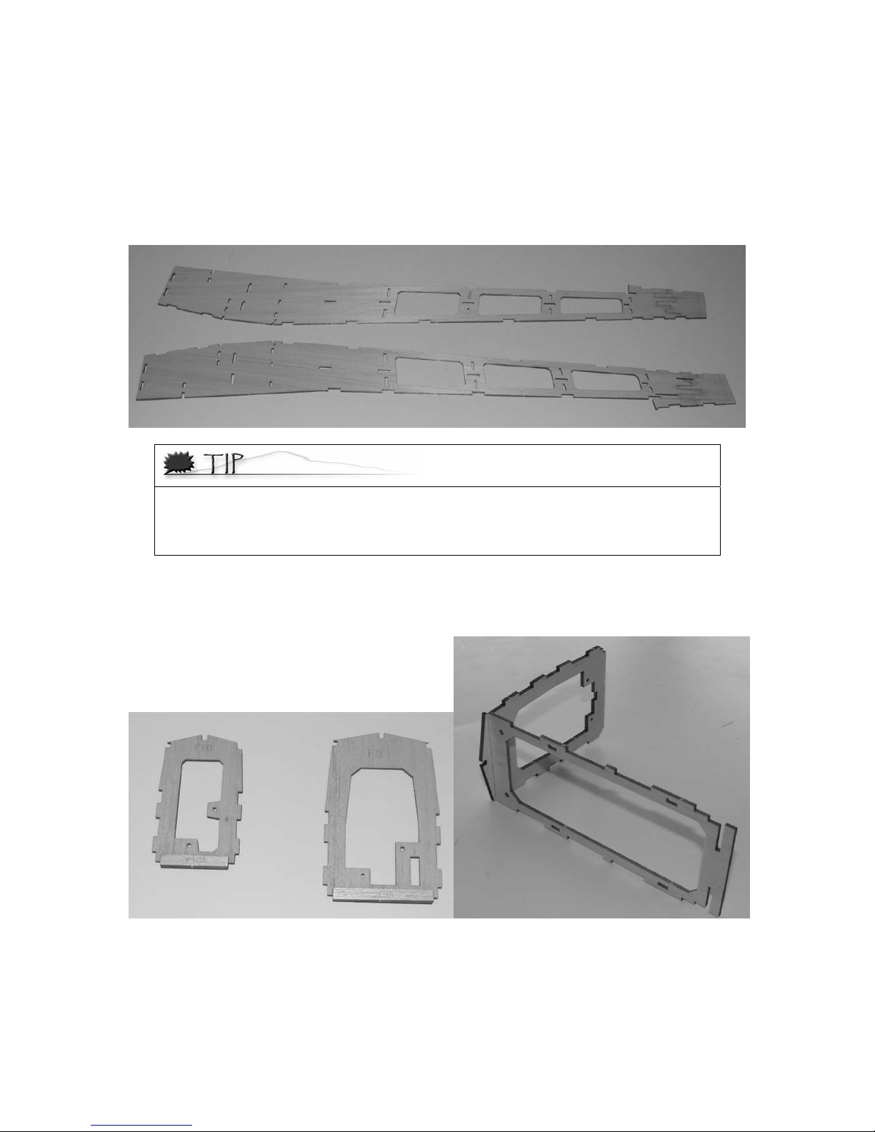
4. Insert a blind nut on each of the 3/32” balsa C9 triangles as shown below. They go on the
“lasered” side of the parts. MAKE SURE the blind nuts are flat against the parts. Secure with a
bit of CA around the outside of the blind nut flange. Make SURE you do NOT get CA on the
inside threads.
5. Insert the reinforcing triangles as shown in the below left image.
6. Slide the 1/8” Lt. Ply F5 onto C8 as shown in the right image above. Make sure the text is
facing away from the other parts. Do NOT glue yet.
7. Press the 3/32” balsa F12 into F11. The text on F12 should be facing UP and the text on F11
should be facing forward (away from F12) as shown in the image below.
6
8. Press the 3/32” balsa F6, with the text facing FORWARD into the RIGHT fuselage side. Insert
the 3/32” balsa F4 into the right side with the text facing FORWARD, as shown in the image
below left. Make sure they are fully inserted and tack glue them in place, making sure they are
at a 90 degree angle to the fuselage side. Press the assembly from step 5 into place on the
right fuselage side as shown in the right image above. Tack glue the formers into place,
making sure they are at a 90 degree angle to the fuselage side.
9. Press the left fuselage side into place on the formers from the previous step, as shown in the
above right image. Make sure the formers are at a 90 degree angle to the side and tack glue
them to the left fuselage side. Make sure the C8 part is all the way in F8 and F5 and tack glue
them together.
10. Insert F9 and F10, with the text facing FORWARD into the right fuselage side. Place the
F11/F12 assembly from step 6 into the right fuselage side. Bend the left side in and press it
onto F9, F10, F11, and F12. Do NOT glue anything yet. Lightly sand the rear inside of the
fuselage parts so they come together nicely as shown below. There are engraved lines
showing about how far back you need to sand and the rear should be about 1/8” thick when
you are done.
7
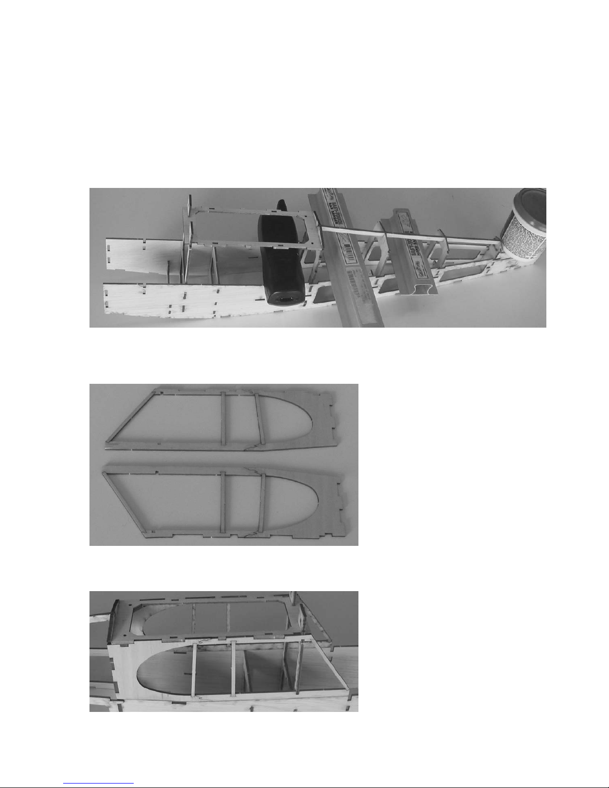
11. Insert the 1/8” balsa F16 part into the tops of the formers as shown below. There will be some
space between the tops of the middle formers and the top of F16. This is so the formers do
not touch the covering when you’re done. Line up the fuselage on the top view of the plans.
The top view on the plans might be a bit long, this is OK, just make sure the back end lined up
on the center line. Weigh the fuselage down to the plans as shown below. After you are sure
all the formers are fully seated and everything is straight, glue the formers and the top
stringer in place with thin CA.
12. Glue the 3/32” balsa cabin sides together over the plans. (Make sure you have wax paper or
plastic wrap over the plans of course!) Make sure that the bottom sides of the parts, with
marks from the laser, are facing the same direction. Each cabin side is on one fuselage sheet.
13. Fit the cabin sides to the fuselage. Make the “lasered” sides face to the inside. Glue them in
place.
8
14. Glue the 3/32” cabin top reinforcements in place as shown in the image below. These go
inside the cabin and seat against the cabin top (C8) part.
15. Insert the 3/32” balsa reinforcements as shown in the image below. They are on the same
sheet as F10. Make sure they are fully inserted before gluing them in place.
16. Insert the 3/32” balsa F3 and F7 parts as shown below, with the text facing FORWARD. Secure
with thin CA.
9

17. Insert 3 of the blind nuts into the 1/8” Lt Ply firewall as shown below. Make sure you put them
on the “lasered” side like below. They are tight, so use a hammer to lightly tap them into
place. Make SURE they are flat and add a little thin CA around the outsides of them. It will
wick into the holes, gluing them in place. Make SURE not to get CA in the threads.
18. Insert the 1/8” balsa F2 in place on the front top of the fuselage with the text facing forward.
Bend the fuselage sides together to mount the firewall as shown above right. MAKE SURE that
the text on the firewall is facing FORWARD! Make sure the sides are straight and glue the
firewall in place. You can trim the front on the fuselage sides back slightly if you want so they
are about 1/8” in front of the firewall.
19. Insert the 3/32” front hatch as shown below. Secure with thin CA. Do NOT glue the hatch
portion of the part to the firewall or F3!
20. Thread the pushrod housings through the formers, starting flush with F8. Secure the pushrod
housings in place with CA. Trim the back end of the housings flush with the fuselage side after
they are glued in place, as shown in the image on the next page.
10

21. Insert and glue F16 into the bottom rear of the fuselage, with the engraved text inside.
22. Insert the 1/8” fuse bottom stringers as shown below, flush with the fuselage bottom. They
are the ones with the square ends. Place them so the “lasered” side is inside the part. Not
outside like in the image. Secure them in place with thin CA. Double check that the fuselage is
still straight before gluing these into place.
23. Insert the 1/16” balsa hatch shelves in place as shown below. They tab into the slots in the
fuselage sides. Secure them with thin CA.
11

24. Insert the rear ¼” balsa washer support as shown in the image above. Make sure it is fully
inserted and secure it with thin CA. You can tell the difference between front and back by
making sure the angle is parallel to the fuselage bottom. Insert the front ¼” balsa washer
support as shown in the image above. Make sure it is fully seated and secure with thin CA.
Glue the washers in place using thick CA, making sure they are pressed up against the former
and centered on the support.
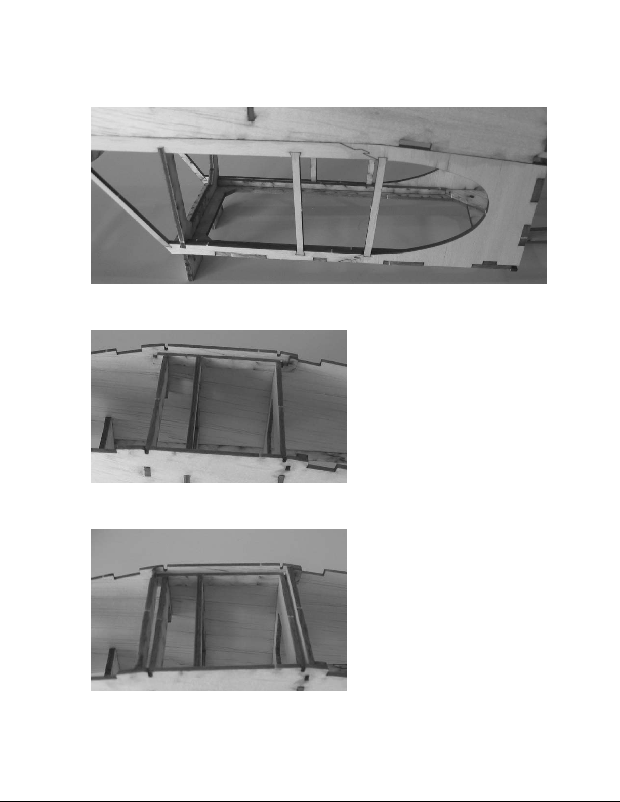
25. Install the 1/8” sq hard balsa stringers as shown below. Trim any extra from the rear to be
flush with the aft former, F11. It will stick out further than the middle formers. This is so the
edges of the formers do not show through the covering when you’re done.
26. Install the side stringers also shown in the above image. They will only fit in the right spot, top
or bottom, so if one doesn’t fit, try the other or rotate it to fit in the slots.
27. Insert and secure the 1/8” front stringers as shown in the image on the next page. F13 goes
in the center, followed by the 2 F14 parts in the middle, and the 2 F15 parts on the outsides.
Make sure they are facing the right direction, fully seated, and then secure with thin CA.
12

28. Glue the 2 1/32” front sheeting parts together using thick CA. Line the centerline of the
sheeting to the middle of F13 and wrap the sheeting around the formers. Make sure it is
aligned and glue it in place with thick CA. Trim any overhang with a sharp blade or sandpaper,
so it is flush with the firewall and F2.
29. Glue the “false ribs” together as shown below and on the plans. BE SURE to make a left and
right side and that the back of the parts are flush.
30. Sand the parts as shown in the image below and on the plans. Glue them to the fuselage as
shown in the image below.
13

31. Insert the RH part with the notch in the center onto the main Rear Hatch part as shown below.
Insert the other RH part also shown below. Glue the parts together using thin CA.
32. Glue the magnet onto the rear hatch on the engraved circle with thick CA. Glue in the 2 1/16”
plywood hatch tabs (marked R) into place as shown in the left image below. The rectangular
RH part goes behind the magnet to reinforce that section of the hatch.
33. Trim the tabs holding in the forward hatch and remove the forward hatch from the fuselage.
Glue the second magnet into place on the engraved circle on the front hatch. Glue in the
remaining 2 1/16” plywood hatch tabs as shown in the right image above.
34. The image below shows the hatches installed. This completes the basic fuselage build.
14

Step 2: Assembling the Landing Gear
1. Bend the 1/16” landing gear wires, using the plans for your pattern. Be VERY careful and take
your time. You want the landing gear to line up nicely, so measure 2-4 times and bend once.
There is an extra piece of wire in case you make a mistake.
2. Lay out the front landing gear wire parts as shown below. Tie them with a single wrap of
spider wire to hold them together as shown below. Solidly wrap spider wire on the 2 top wire
joints. You can use a little thick CA so it sticks at first and then soak it in thin CA when the
wrap is done. You will wrap the outer joints later, and DO NOT wrap the center joint! With the
center joint wrapped, the gear is extremely stiff and has no shock absorption.
3. Glue the 1/16” balsa landing gear core to one of the 1/32” ply parts as shown below. If the
center holes do not line up, rotate one of the parts 180 degrees so they do line up. It is best
to use 5 minute epoxy here to make sure you get a very solid glue joint. After the glue is dry,
trim out the 3 tabs on each side so the landing gear wire can fit in the slots.
4. Insert the landing gear wires into the gear mount as shown below. Use the remaining spider
wire to wrap the wires on the outside by the axles as shown below. Make sure the landing
gear wires are staying flat in the landing gear mount slots while you are doing this. Once
again, DO NOT wrap the center joint!
15

5. Glue the other 1/32” ply part to close the wires in the landing gear mount. Use epoxy here to
make sure you get a solid glue joint. Clamp the parts together until the glue is dry. After
everything is dry, remove the single spider wire holding the center joint together.
6. Trim the 1/16” balsa landing gear fairings to fit as shown below. We made these slightly
oversize to account for differences in assembling the landing gear wires. Glue them to the
wires using thick CA.
7. Bend the tail wheel wire as shown on the plans, using the 0.039” wire.
16

Step 3: Assembling the Tail Parts
1. Assemble the horizontal stab and elevator parts over the plans. After all parts are pressed
together, secure each joint with thin CA.
2. Trim the long 1/8” dowel to 4” and glue to the elevators with thick CA or epoxy.
3. Assemble the vertical stab and rudder over the plans. After the parts are all pressed together,
secure with thin CA. Make sure you don’t glue the rudder to the vertical by accident, so
assemble them separately. MAKE SURE the top rear of the vertical and the inside corner of the
rudder are square at a 90 degree angle so they fit together nicely after they are assembled.
17

4. Assemble the rear fuselage to tail fillets as shown below. MAKE SURE you assemble a LEFT
and RIGHT side. Temporarily assemble the tail parts to the fuselage. Place the fillets on the
stab against the vertical fin and mark the front of the fillets where they meet F11. Remove the
vertical and stab from the fuselage and then place the vertical back in the slots without the
stab. Mark the bottom of the fillets where they meet the fuselage sides. Sand the fillets to the
lines you marked. The fillet should be sanded to almost 0 thickness at the back end.
Step 4: Assembling the Motor Mounts
There are 3 motor mounts included in the kit. There is a stick mount for the GWS geared brushed
systems, a rear mount for outrunners, and a front mount for outrunners. The outrunner mounts
have mounting holes for 16mm and 19mm spacing. Due to tolerances on the Light Ply we have
been getting, the parts might be slightly loose or slightly tight. If they are tight, sand them slightly
for a better fit. If they are a bit loose, use some thick CA in the joints to make sure you get a good
glue bond.
1. Below are pictures of the rear firewall mount. The front firewall mount goes together the same
way. The taller 1/16” ply firewall parts are for the mount pictured. Press the 1/8” sides onto
the 1/16” ply part, with the “lasered” sides of the parts facing inwards. Place the top part with
the text facing outside the part. Place these onto the mount as in the 3
everything is seated fully, secure with thin CA and then a small fillet of thick CA around the
joints. Glue the 1/16” ply doubler to the front to complete the motor mount.
rd
picture. After
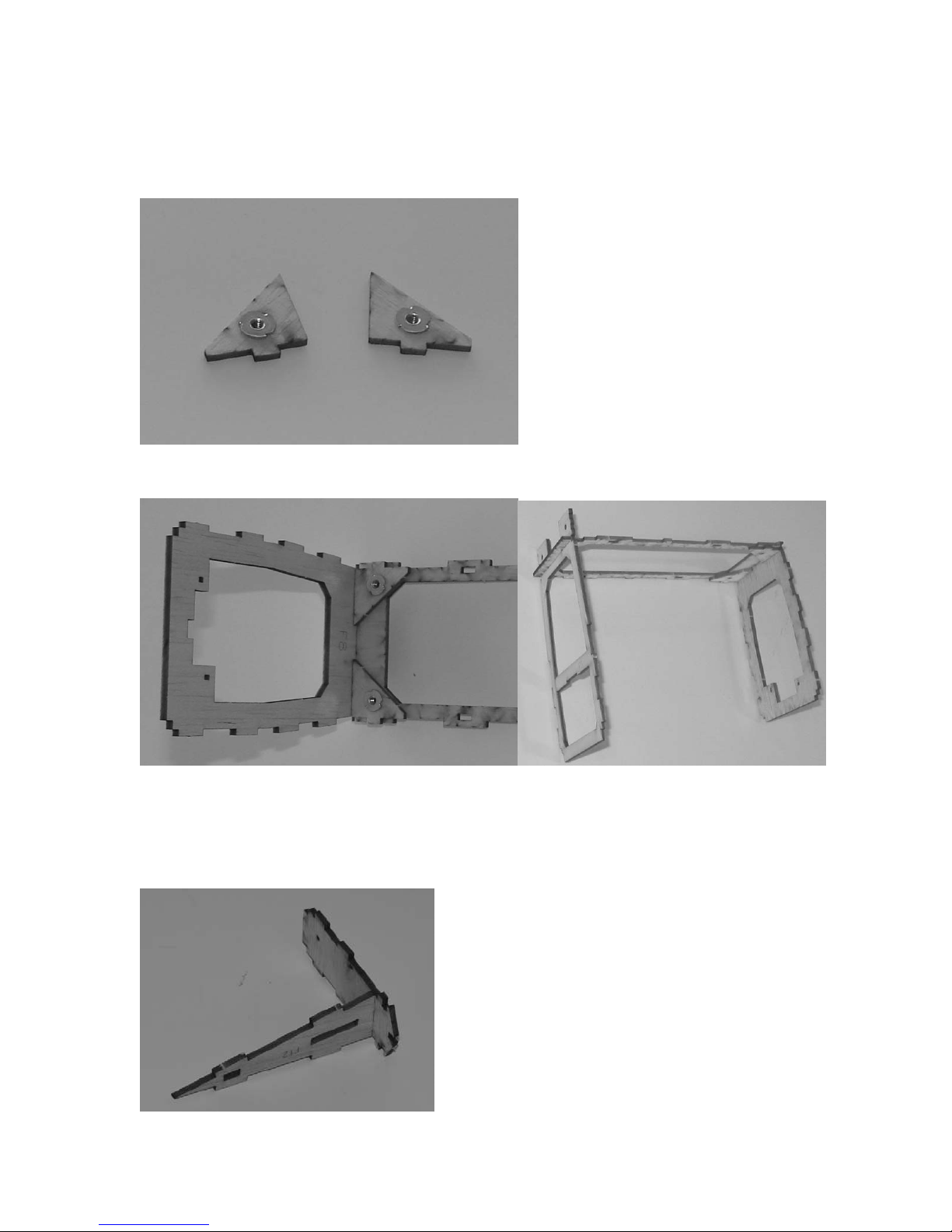
2. For the stick mount, make sure that the “lasered” sides of the parts are all facing inside.
Assemble the long rectangular part to the right side as shown in the first image. Add the left
side as shown in the second image. Add the top as shown in the third image. Press the
assembly into the stick mount back as shown in the last image below. After you make sure
everything is fully seated and assembled correctly, glue the joints with thin CA. Reinforce the
joints with some thick CA for a nice strong stick mount. (Images are on the next page)
18

Step 5: Sanding and Covering
The next step is to sand the pieces that need to be sanded and cover everything.
We aren’t going to go into how to cover the pieces themselves,
you’re going to have to refer to your covering’s instructions for this information.
Sanding the Cub
What we recommend:
• 320 grit sandpaper for sanding, 400 grit if you want an even smoother finish.
• While sanding, try to go over the entire edge in a sweeping motion.
• Make sure that you sand lengthwise with the grain and not across it, as this will
cause less strain on the wood, less chance of breaking the pieces, and a smoother
finish.
• Using a tack cloth, carefully remove the balsa dust once you are done sanding.
What to Sand
On the tail parts, first lightly sand each side of them so all the part joints end up nice and
smooth. Use a sanding block long enough so you don’t nick the edges of the internal
structure as you sand. Start out with 320 grit to get everything to the same plane and then
lightly sand the parts with 400 grit for a nice finish. Now, round all the outside edges and
the hinged edges. Do NOT round the bottom edges of the vertical where it will join or insert
into the fuselage. Don’t skip this because square edges really don’t look good after it’s
covered.
19

On the fuselage, sand all surfaces that will be touched by covering for a nice smooth finish
when you’re done. Slightly round the corners of the 6 fuselage side stringers and top
stringer. Sand the bottom so everything is nicely smooth and flat. Lightly round the bottom
corners of the fuselage.
Before covering, we like to check the fit of the wing in the fuselage. Remember that you’ll
have a couple layers of covering where the back of the wing meets the fuselage, so sand
this area slightly if it seems a bit tight.
Covering the Cub
Determine what material you’ll use to cover, we recommend using SoLite covering material
since it is extremely lightweight and won’t crush the balsa when shrinking.
Do not shrink the covering until both sides of each part are covered. This reduces your
chances of twisting the surfaces. Also, use a cotton iron to prevent scratching the
covering. We usually use one sock for the wings, one for the fuse, and if we need to, a
new one for the tail and other miscellaneous parts.
Following your covering material instructions, cover the pieces in the following order. This
will let you cover the model with 1 roll of covering, which is a good thing!
• Wings: Cover the bottom left side of the wing, then the bottom right, then top left, and
finally, the top right. After it is all covered, shrink the covering with your iron. Using a
heat gun increases the risk of melting a hole in the covering, so we prefer an iron.
• Fuselage: We like to do the sides, then the bottom, and then the top. In the area where
the covering goes from the side stringers to the rear window area, we like to have the
covering attached to the stringer and then the inside edge of the windows, so it flows
nicely and doesn’t sink down.
• Tail Feathers: Cover each side before shrinking the covering to help prevent warps.
• Ailerons: Cover each side before shrinking the covering to help prevent warps.
• Hatches
• Landing Gear Mount: Cover only the bottom of the mount so you get a good glue bond
later on. Cover the landing gear balsa triangles. Go around the wire on the front and
back so it looks nice.
• Struts
• Rear Fuse “fillets”, Control Horns, Strut Mounts, Etc.
Step 6: Installing and Finishing the Landing Gear
You want to make sure you get a good strong glue joint here! Make sure there is no
covering where the landing gear mount meets the formers and sides of the landing gear
area of the fuselage. Test fit the landing gear. Sand the mount slightly, if you need to, so it
can be fully inserted into the fuselage. After you are sure it fits well, apply epoxy to all the
mating surfaces; former bottoms, front and back, and sides. Press the mount firmly into
place and allow it to cure. When it is drying, double check again that it is pressed firmly in
place. After dry, you can add some small glue fillets to the inside to really make sure the
landing gear is glued firmly into place.
20

• Clean the inside edges of the 4 aluminum tubes with an X-Acto blade.
• Slide the 3/32” OD Aluminum tube over the landing gear axles. Fix them in place with a
bit of thin CA wicked into the tubes. DO NOT try to put CA on the wire before the tubes
are in place!
• Press the 1/8” Aluminum tubes into the wheels.
• Slide a #4 Non-Magnetic washer over the 3/32” tube on each side.
• Press the 1/8” Aluminum tubes into the wheels.
• Slide the wheels onto the 3/32” axle. And secure them to the axle with the wheel
retainers. (These are the black “washers” with the internal teeth.)
• Cut a small hole and slit into the rudder for the tail wheel wire to fit into, as shown on
the plans. The wire should fit into the rudder nicely so you still have a straight hinge
line. After you’ve triple checked the fit, glue the wire in place with thick CA. Take care
not to get CA on the covering, as it can leave a nasty white residue that doesn’t look
good.
• Slide the tail wheel onto the tail wheel wire. You can keep it in place with a drop of thick
CA, kicked with accelerator immediately so the CA does not go into the wheel. BE VERY
careful so the CA does not go into the wheel! You can do multiple drops to get a larger
wheel “keeper” on the end of the wire.
Preparing for the CA Hinges
We will be using CA hinges because they are easy to work with and quite strong.
Cutting the Hinges
• Cut the 2 hinges in half and then cut those 2 pieces in half so you end up with 8 hinges
for the tail parts.
Cutting the slits
• Cut 1/4” wide slits into the stabilizer and elevators (2 per stabilizer side), vertical fin
and rudder (3 hinges), and the rear of the fuselage as shown on the plans. The slits
should be exactly centered in the thickness of the wood.
21

Step 7: Installing the Tail Feathers
For this step, you are going to install the horizontal stabilizer, elevator, the vertical
stabilizer and the rudder to the fuselage. When removing covering for gluing parts, be
GENTLE with the X-Acto so you don’t cut into the parts!
1. Trim the covering from the slots in the horizontal stabilizer where the vertical fin will go
through. Trim the covering from the bottom of the vertical where it will be going through the
stab.
2. Set the stab on the fuselage and press the vertical through the slots in the stab and into the
slots in the fuselage. Mark the covering on the bottom of the stab where it meets the fuselage.
Remove the vertical and stab from the fuselage. Carefully remove the covering just inside the
marking you made on the stab bottom. This will give you a good glue joint between the
fuselage and stabilizer.
3. Apply a light coat of epoxy to the bottom of the stab where it will glue to the fuselage. Install
the stab and vertical to the fuselage again, making sure that the stab sits flat on the stab
mount area. Make sure the vertical is at a 90 degree angle to the stab BEFORE the glue sets.
Allow the glue to dry before continuing.
4. Set the rear fuselage “fillets” in place on the stab. Mark the covering on the stab and elevator
where the fillet meets them. Remove the covering in these areas just inside the marks for a
good glue joint. Glue the “fillets” into place to the stabilizer and vertical.
5. Press the CA hinges into place in the slots for the horizontal stab. Slowly work the elevator
onto the hinges. Make sure the elevator moves freely and secure the hinges by drops of thin
CA on the joints of the hinge and part. You can bend the elevator down while gluing the hinges
from the top, then bend the elevator up to glue the hinges from the bottom side.
6. Hinge the rudder to the vertical and fuselage just like the elevator. Secure the hinges with thin
CA like you did on the stab/elevator.
Step 8: Installing the Control Horns, Servos, Linkages, and Misc.
• Miscellaneous
1. Glue in the Wing Strut Mounts as shown in the image below Do NOT glue it in upside down!
22

• Installing and hooking up the Control Horns
1. If you covered the control horns, remove the covering on the tab that goes into the rudder
and elevator. Trim the covering over the slot that the horns press into on the elevator and
rudder. Glue in the control horns, with thick CA, as shown in the image below.
2. Place an L-bend on one end of the two 0.032” pushrod wires. Press the pushrod into the
pushrod tubes and use the DuBro Micro EZ Connectors to secure the pushrods to the control
horns as shown above.
• Installing the servos
1. Install the DuBro Micro Servo Connectors onto the servo horns as shown below.
2. Slide the servo connector onto the pushrod wire and use aggressive double sided tape or some
drops of thick CA to secure the servos to the sides of the fuselage as shown above. Trim the
extra wire sticking out, but leave some for adjustments.
Step 9: Windows and Plastics
The easiest way we have found for trimming the vac-formed plastic parts is to use
sandpaper. Trim the parts out of the sheets about ¼” outside the part to begin.
1. Glue the windows on, staring with the front window, then the sides. You can use a small bead
of thick CA, but the best glue to use is something like the Pacer canopy glue that you can find
at local hobby stores. On the front window, take your time and get it lined up right. BE
CAREFUL not to crush the front cabin parts. After it lines up well, glue the sides and then bend
23

the top over and glue that part of it. Trim any excess off the top part of the front window after
the glue dries.
2. For the vac-formed parts, start with the cowling itself. After trimming it out of the sheet, lay
some sandpaper on your flat hard building surface. With even pressure, rub the cowling
around the sandpaper in a figure-8 pattern. When the plastic edges start to fall off, you are
there. Peel the edge off for a nicely trimmed part. You can use a bit of sandpaper to clean up
the edge even more if you need to. Trim out the holes for the motor shaft and the 2 holes
below the motor opening with an X-Acto blade as shown in the image below.
3. Repeat the above process for the engine details. Since the details are not flat, you can’t sand
the edges like above, but you can use sandpaper on the back of the part to get there. This is a
lot easier than using an X-Acto blade to start with, especially if you slip and cut into the part.
We’ve all been there and done that, so take your time and try the sandpaper method, it
works!
4. For really nice air inlets for cooling the motor, ESC, and battery, try the following; Trim the
front of the engine details as shown below. After you’ve trimmed this area loose, bend the
plastic back into the engines. You’ll need to trim some off the inside so it sits nicely against
the cowling as shown in the second image.
5. Glue the engine details to the cowling in the positions shown on the top view of the plans with
plastic modelers cement. After it’s dry, trim out some holes in the cowling behind the engine
details. You can cut these before gluing the engine details on, but make sure you don’t cut
outside of where they will mount.
24

6. Paint the cowling and engine detail with the paint you have chosen. If you use Yellow So-Lite,
Krylon Fusion Sunbeam/Safety yellow is a fairly good match.
Step 10: Installing the Motor and Cowling
We recommend a brushless outrunner rated for around 80 to 100 watts.
! Installing the Motor
1. Decide which mount you are going to use. Because the motor mounts unbolt, you can change
mounts later.
2. If you use the rear firewall mount, pictured below, mount the motor to the firewall, and then
bolt the motor mount to the firewall using the included 4-40 hex-head bolts.
3. If you use the stick mount for a GWS geared brushed system, use the included #2x3/8” wood
screw to secure it to the motor stick.
4. Slide the cowling onto the fuselage, lining up your prop shaft in the middle of the cowling.
Secure the cowling to the fuselage using the 4 small screws included in the parts bag.
25

Step 11: Attaching the Receiver and Speed Controller
We are not going to cover the receiver and speed controller (ESC) specific information, please
refer to your manufacturer’s instructions for more information, if necessary.
! Attaching the Receiver
• The receiver is attached within the fuselage, in front of the servos. Use adhesive Velcro
and attach it to fuselage side. Connect the servos and ESC to the receiver, following the
guides on the receiver itself.
! Attaching the ESC
• The speed controller can be attached within the fuselage, forward of the batteries. I just
let my ESC hang loose. Connect the battery and the motor to the ESC, following the
guides on the controller itself.
Step 12: Finishing the Kit
Well, you’re almost there…the end is in sight; just a few more steps and you can go flying,
assuming the weather is cooperating.
Attaching the Battery
! Attaching the battery
1. The battery mount location is flexible to handle the different weights of motor and battery
options. We mounted the stick on the bottom of the formers to allow the battery to be
changed from the bottom of the plane, instead of having to remove the wing every time,
which would have been VERY annoying.
2. Determine approximately where the battery will need to be placed to establish your CG. Glue
the battery tray in place, giving you room to move the battery forward and back if you need
to. Secure the battery tray VERY well with thick CA or epoxy.
3. Attach the soft side of the Velcro strip to the bottom of your battery pack, and the pointy side
to the battery tray.
26

4. After you attach the battery pack onto the mount, run the 6” double-sided Velcro strip
underneath the battery mount, around the top of the battery pack, and then secure it to itself
snugly. This acts as a seatbelt, holding the battery pack securely in place.
Attaching the Wing
1. Plug the wing into the front mount and use the nylon bolts to secure it on the back.
Use a 4-40x3/8” Screw and nut to secure the wing strut to the fuselage. The wing strut goes
to the rear of the fuselage mount.
Setting the Throws
You need to adjust your radio trim so that the elevator, rudder, and ailerons are all level. The
throws are listed as total travel, and are as follows:
Low Rates High Rates
Ailerons
Elevator
Rudder
See Wing Kit Instructions See Wing Kit Instructions
3/4” 1”+
3/4” Whatever you can get.
Setting the Center of Gravity
The Center of Gravity (CG) will affect how the airplane recovers from a nose up or nose down
condition (pitch stability). With the CG too far forward, the plane will be quite stable, but
require some up elevator to fly level. On the other hand, too far back and the plane will be hard
to control, requiring constant input to keep the plane flying straight and level. For the Cub, start
with the CG at the front of the range on the plans. Use this as a starting point and then you can
slowly move it back as you like.
Scale Additions and/or Modifications
The outlines of our Cub kit are very true to scale. Of course, in making a kit easier to build, we
did simplify some areas. For a more scale Cub, try some of the following;
1. Add some bungee covers to the landing gear.
2. Add some covers to the main wheels and paint them yellow.
3. Add the V-braces to the top front of the fuselage going up to the front of the wing mount
section. 1/8” dowel would work well for this.
4. Add some Exhaust tubes to the engine details.
5. Add a fuel gauge to the top front of the fuselage.
6. Add the strut braces from the X-brace section up to the wing. For extra credit, raise the center
strut brace above the struts themselves.
7. Create a scale tail wheel assembly. You might try laminated 1/64” plywood strips to form it.
8. Change to a pull-pull setup for the elevator and rudder. For extra credit, change the ailerons
to a pull-pull as well.
9. Create a cover for the landing gear center section. For SUPER DUPER TRIPPLE extra credit,
create a functional bungee landing gear!
10. The sky’s the limit!
27
 Loading...