


EZ CUB
EZ Cub Specifications
Wingspan: 36 in.
Length: 22.6 in
Wing Area: 232 sq. in.
Weight (Ready to Fly): 12 oz
Wing Loading: 7.4 oz/sq ft
Controls: 3 or 4
Version 1.05, February 5, 2008
© 2008 Mountain Models all rights reserved
1

Thank you for purchasing the EZ Cub™. The Mountain Models EZ Series™ planes are meant to
be the easiest kit build possible, while still having great flying characteristics and high
durability.
The EZ Series™ can be flown as 4-channel versions (rudder, elevator, throttle, and aileron) or
with the higher dihedral wings as 3 channel (rudder, elevator, and throttle).
The EZ Series™ was designed for the complete beginner builder and low experience pilots. For
those who are more experienced, the EZ Series™ still offers fun flying and some great
performance with the CG moved back a bit.
For those of us on a time budget, this kit will build up in as little as 3-4 hours, which is even
faster than a lot of ARF’s that are available.
We know you’ll enjoy the EZ Series™ planes and look forward to any feedback or questions you
might have.
Sincerely,
Brian Eberwein
sales@mountainmodels.com
Mountain Models guarantees this kit to be from defects in material and workmanship for the
original purchaser. Since we have no control over the assembly of the final model, we accept NO
liability for any damage or harm caused by the final product resulting from the user. By building
this kit, you accept sole responsibility and liability from its use.
If you, the original buyer are not prepared to accept the liability associated with the use of this
product, return the kit immediately in new and unused condition to us for a refund.
Mountain Models reserves the right to change or modify this warranty without notice.
WARRANTY
Mountain Models
PO Box 9557
Colorado Springs, CO 80932
www.mountainmodels.com
Phone: 719.630.3186
© 2008 Mountain Models all rights reserved
2

Before You Begin
Before you begin building your EZ Cub™, make sure that all the wood sheets and parts, and
hardware are present in your kit. In the unlikely event that something is missing, please contact
us immediately and we will send it to you right away.
Make sure you read and understand all of the instructions thoroughly before beginning
assembly of this kit.
Recommended Electronics:
• 2 ea. Micro servos for 3 channel version (GWS Pico, Naro, HS-55, or similar)
• OR 3 ea. Micro servos for 4 channel version
• 1 ea. Mini Receiver (Berg 4L is highly recommended)
• 1 ea. Scorpion 2205 Brushless Outrunner (or 80 to 100 watt equivalent)
• 1 ea. 3S-800 to 3S-1200 LiPo Battery
• 1 ea. 15A to 18A Electronic Speed Control (depending on motor choice)
Tools You Will Need:
• Smooth and FLAT work surface
• Plastic wrap or Wax paper to protect the work surface
• Thin and Thick Cyanoacrylate (CA) glue
• 5 to 10 Minute Epoxy
• Hobby knife with #11 blades
• Wire cutters
• Soldering iron for ESC and battery connectors
• Small screwdrivers and needle nose pliers
• OPTIONAL: Sealing iron if using iron-on covering
Items for Finishing:
• Sanding block with 220 to 400 grit sandpaper
• 2 Rolls Wing tape of different colors
• 3M-77 spray adhesive.
• Water-based polyurethane spray, fast drying
• Clear Tape for hinging control surfaces
• OPTIONAL: Balsa wood filler, lightweight
• OPTIONAL: Iron-on covering and trim
© 2008 Mountain Models all rights reserved
3

Fuselage Parts List:
• This Manual … If you do not have the manual you are holding, please call us. ☺
• Laser Cut Wood Bundle
o 3 ea. 1/16” x 4” x 24” Balsa
o 1 ea. 1/16” x 3” x 24” Balsa
o 1 ea. 3/32” x 4” x 24” Balsa
o 1 ea. 1/8” x 3” x 11.5” Lt. Plywood
o 1 ea. 1/16” x 3” x 7.75” Plywood
• 2 ea. Yellow Pushrod Tubes x 12”
• 2 ea. 0.032” x 18” Wire
• 1 ea. 1/16” Pre-bent landing gear wire
• Parts Bag
o 2 ea. DuBro 1-1/2” Wheels
o 1 ea. DuBro Tail Skid
o 2 ea. DuBro Wheel Collars & Set Screw
o 4 ea. 4-40 x 3/8” Screws
o 4 ea. 4-40 T-Nuts
o 4 ea. #4 Washers
o 1 ea. 1/2” x 6” Double sided Velcro
o 1 ea. 3/4” x 3” Sticky backed Velcro (loop & pile)
o 2 ea. Micro EZ Servo Connectors
o 2 ea. DuBro Micro EZ Links
o 2 ea. 1/32” Plywood landing gear squares
o 2 ea. 1/64” Plywood elevator reinforcement rectangles
Wing Parts List:
• Foam Wing Core
• Laser Cut Wood Bundle
o 1 ea. 1/16” x 3” x 24” Balsa
o 1 ea. 3/32” x 3” x 24” Balsa (Aileron version only)
o 1 ea. 1/8” Plywood wing “rib”
o 2 ea. 1/64” Plywood spar braces
o 2 ea. 1/16” Plywood Aileron horns (Aileron version only)
• 1 ea. 0.032” x 9” Wire (Aileron version only)
• Parts Bag (Aileron Version Only)
o 2 ea. Micro EZ Servo Connectors
o 2 ea. DuBro Micro EZ Links
© 2008 Mountain Models all rights reserved
4
General Building Tips
• Balsa is a lightweight and fragile wood, so you do need to be somewhat careful with it;
however, you might also need to use a little bit of force to make everything fit properly,
so don’t be too timid.
• Join all of your pieces using thin CA (Cyanoacrylate) glue, unless we tell you otherwise.
In general, only a small amount of CA is necessary to glue parts together. Do NOT glue
anything until the instructions tell you to.
• Don’t remove any pieces from the balsa sheets until they’re ready to be used. That way,
parts won’t get mixed up or disappear.
• Don’t over force your pieces together. If they aren’t going together properly, make sure
you have the right pieces and that they are oriented correctly.
• If you want to remove the charred edges caused by the laser cutting process, dampen a
cloth with bleach and gently rub the affected areas. Removing the char will not increase
the strength but will make it look better.
Assembly Instructions
Experienced builders may notice that this building order goes
against the “normal” building conventions. We have found that fewer pieces get mangled this
way, since you are building the stronger pieces first. For example, the tail feathers are at the
end of the build process instead of the beginning, so that they are less likely to get underfoot
(which seems to be a recurring problem) and are being built right before they are attached to
the fuselage and each other.
Section 1: Assembling the Fuselage and Tails
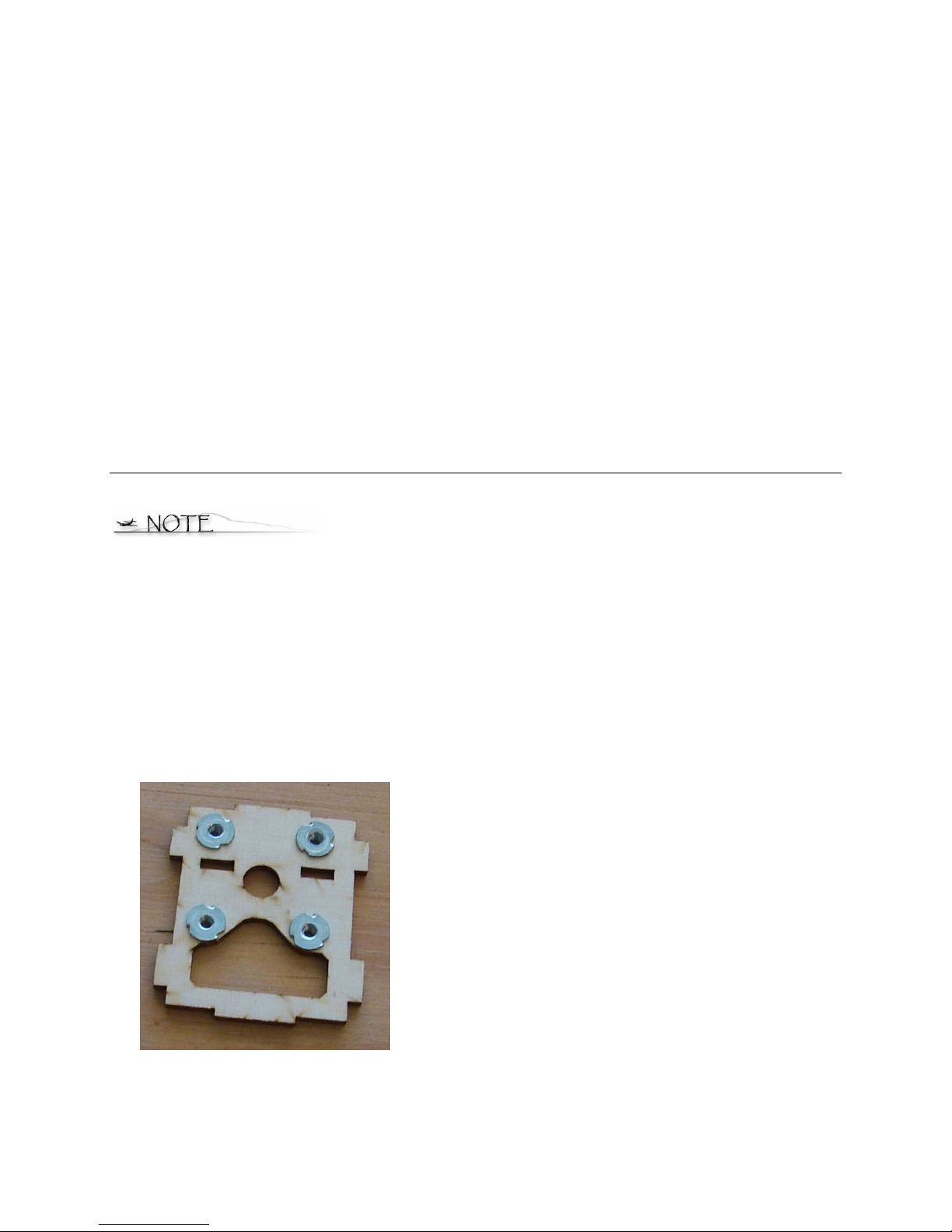
1. Press the 4-40 T-nuts into the front former as shown below. Make sure to install the
blind nuts on the “dirty side” of the parts, NOT the side that is engraved. Secure the Tnuts with thin CA around the outside of the T-nuts AFTER you are sure they are fully
seated and flat against the wood.
© 2008 Mountain Models all rights reserved
5

2. Glue the 1/16” plywood rectangle brace to the FRONT of the front 1/16” plywood
former, using thick CA. Use the engraved line for placement.
3. Insert the 1/16” plywood front former through the 1/8” Lt Plywood crutch as shown in
the image above. MAKE SURE that the engraved “TOP” on the crutch is facing UP and
that the engraved “FRONT” on the former is facing forward. Slide the former into place
as shown in the image on the next page. Do NOT glue it yet.
© 2008 Mountain Models all rights reserved
6

4. Press the 1/16” plywood rear former into place on the back of the crutch, with the
engraved “FRONT” facing forward as shown in the image below. If it seems tight, place
the former flat on the table and press the crutch into it. Do not glue it yet.
5. Press the front 1/8” Lt. Plywood firewall onto the crutch. Ensure that the T-Nuts are on
the “inside of the fuselage, as shown in the image below. Once again, if it seems tight,
place the firewall flat on the table and press the crutch into it. Do not glue anything yet.
6. Press the 1/16” balsa former into the crutch as shown above. No, you still don’t get to
touch the glue bottle.
7. Press the 3/32” balsa lading gear top support into the front 1/16” plywood former as
shown below. It gets placed on the “back” of the former.
© 2008 Mountain Models all rights reserved
7

8. Press the 3/32” balsa landing gear rear support into place as shown below. If it is a bit
loose, you can use a SMALL drop of thin CA to keep it in place.
9. Slide the 1/16” balsa interior doublers into place over the crutch and formers, as shown
in the image below. If it looks like the tabs don’t line up, try putting it on the other side.
The parts are made to only fit on the correct side. Be careful when pressing the parts
on, and don’t get heavy handed. Slide them a bit at a time, until they are fully pressed
on. Making sure everything is pressed fully into place; secure all joints on the inside with
thin CA. Be careful where your fingers are when gluing the parts together. You don’t
want your fingers to get glued at the same time, now do you? I hate to think of how
much skin I’ve left behind on models I’ve built over the years from careless use of CA…
10. Press the 1/16” balsa fuselage sides into place as shown below. Press them flush onto
the doublers between the 1/16” plywood formers, but do not bend them to the nose yet.
Secure the sides to the doublers using thin CA applied from the inside of the fuselage,
through the holes in the doublers. On the nose, you can use thick CA applied to the
doublers, BEFORE you pull the sides fully onto the doublers. This makes for a very well
glued nose section with a good bond between doubler and side.
© 2008 Mountain Models all rights reserved
8

11. Glue the 3/32” balsa bottom cross brace into place using thin or thick CA, as shown
below.
12. Test fit the 1/16” balsa front bottom sheet, as shown below. If it doesn’t seem like it
fits, flip it over and try again. The slot is angles to match the front former. After it’s in
place, secure it around the joints with thin CA.
13. Test fit the 1/16” balsa front top sheet. Like above, after it’s in place, secure the joints
with thin CA.
14. Put the 1/16” balsa canopy front in place and secure with thin CA, as shown below.
© 2008 Mountain Models all rights reserved
9

15. Pull the rear of the fuselage sides together and use a piece of tape to hold them in
place, making SURE they are lined up at the back. Install the 1/16” balsa rear bottom
part. Secure it with thin CA, making sure it is fully pressed into place.
16. Install the remaining 1/16” balsa bottom part and secure with thin CA.
17. Slide the pushrod tubing in place, as shown below. Leave them about 1/8” in front of the
former, with the remainder going out the fuselage sides at the rear. Please note that
they cross each other near the back of the fuselage. Use some thin CA to tack them in
place. Then use some thick CA to form a small “fillet” between the tubes and the former
on the front and back of the former. Trim the rear of the pushrod housing about 3/4” in
front of the rear of the fuselage.
18. Install the top rear 1/16” balsa sheet. Secure with thin CA, and MAKE SURE that the
fuselage is not twisted while you are gluing it in place. (See image below)
19. Press the 3/32” balsa rear top stab support in place, and glue with thin CA. (shown in
above image)
© 2008 Mountain Models all rights reserved
10

20. Glue the 1/16” plywood battery support in place with thick CA, as shown in the image
below.
21. Bevel the hinged surface of the lower rudder part to a 30 degree angle. You can do this
with a sanding block. For a nice crisp edge, set the part on a steel ruler, with the edges
lined up, when sanding.
22. Press the rudder parts together on a flat surface and glue them together with thin CA.
23. Glue the 1/64” plywood elevator reinforcement plates to the elevator as shown below,
using thick CA. One goes on each side, lined up with the rear “joiner” section. The
narrower plate will be spaced back from the hinge line slightly.
24. Bevel the elevator, like you did the rudder, to a 30 degree angle.
25. Lightly sand the entire fuselage and tail parts. Slightly rounding the outside corners
looks better than leaving them square, but you don’t have to if you don’t want to.
© 2008 Mountain Models all rights reserved
11

Section 2: Assembling the Wing
1. Remove the wing cores from the beds. Do NOT throw away the beds, as they are used
later. Remove the foam “fuzz”, from the cutting process, by rubbing the wing lightly with
your hands. If you’d like, you can lightly sand the cores with some fine sandpaper. Do
NOT get too aggressive though, as the edges of the sandpaper can dig into the foam,
giving you a dent in the wing.
2. Before gluing the wings to the plywood rib, make sure you are gluing them on the
correct sides. The wings should go in a slight upward “V” shape. This is called dihedral
and provides some stability in flight. Glue the wing cores, with epoxy, to the 1/8”
plywood “rib”, making sure that the bottom of the wing matches up with the engraved
lines on the rib. The back of the wing should be flush with the back of the rib. Taping
everything together, as shown below, will help keep everything in place until the glue
dries. Check it while the glue is drying to make sure the cores have not shifted.
3. Cut the foam beds at the “leading edge”. And set the “bottom right” side on the table, as
shown below.
4. Place some plastic wrap over the bed, to keep from gluing the wing to the beds. Set
another sheet of plastic to the side for use later.
5. Read steps 6 through 9 and try a “dry run” before you try gluing anything. You want to
make sure you know what you’re about to do, so practice it without glue first.
© 2008 Mountain Models all rights reserved
12

6. Mix up some epoxy for gluing in the spars. Place some epoxy in the bottom right spar
slot in the wing and spread it out to the tip with the end of one of the 1/16” balsa spars.
7. Place the 1/16” balsa spar in place, overlapping the 1/8” plywood rib half way.
8. Place the wing into the bottom foam bed and repeat step 6 for the top spar slot.
9. Place the extra sheet of plastic wrap over the wing and them place the top half of the
foam bed in place. Weigh this down while the glue dries with magazines, books, or
weights of some kind. This will make sure the wing dries to the right angles.
10. Repeat steps 4 through 9 for the other side of the wing. When gluing the left side spar
caps, MAKE SURE that they are pressed up against the right caps and glued well, with
no gaps.
11. Glue the 1/64” plywood “darts” to the top AND bottom spars, as shown below. You can
use thick CA if you are careful not to get any on the foam. Use some plastic wrap over
your fingers, so you can hold them in place until the glue dries.
© 2008 Mountain Models all rights reserved
13

12. A note on 3M-77 spray adhesive. There are 2 forms of 3M-77 spray adhesive. The
“new” formula of 3M-77 has acetone in it. Acetone melts foam. You can still use this
“new” formula, but lightly spray it from a distance of 18” away from the wing to let the
acetone vapor off before it hits the wing. 3M has also released a new “Foam” spray
adhesive that is supposed to be safe for polystyrene foams. If you can find this, it would
probably be safer than the acetone version of 3M-77.
13. Lightly spray the wing with your foam adhesive. This will help the tape adhere nicely.
After letting it sit for a couple minutes, begin taping your wing. When applying the tape,
start at the center section of the wing, overlapping the center by about 1”. Press and
smooth out the tape a little at a time. Press down, unroll a bit more tape, press it down,
and repeat until you get to the wing tip. Doing it like this will prevent wrinkles in your
finish.
14. Start from the trailing edge, with the middle of the tape on the trailing edge and overlap
the top and bottom, as shown below.
15. Overlap each “row” by ½” to 1”. If you don’t want to see the darker “strips” where the
tape overlaps, overlap each row half way, so there are 2 layers of tape. This will add
some more weight to the finished wing, but it shouldn’t be a problem.
16. Leave the leading edge “uncovered” until you have the top and bottom covered most of
the way to the leading edge. The last strip of tape you place should be on the leading
edge, around to the top and bottom. Your finished wing will look something like the
image below.
© 2008 Mountain Models all rights reserved
14

17. AILERON VERSION ONLY: Sand a 30 degree bevel on the hinge side of each aileron,
as shown in the image. Lightly sand the entire surface of each aileron with fine
sandpaper. If you are covering your ailerons with an iron-on film, do it now.
18. AILERON VERSION ONLY: Glue the 1/16” plywood aileron horns in place with thick CA,
as shown above.
Section 3: Finishing the Fuselage
1. If you are covering your fuselage and tails with an iron-on film, do it now. Refer to the
instructions that came with your covering for how to do it, if you are new to iron-on
films.
2. Press the vertical fin into the horizontal stab, as shown below. Make sure it is pressed
fully into place and secure with thin CA, making sure they are at a 90 degree angle to
each other. You can use the 1/16” plywood sheet for a 90 degree angle guide if you do
not have anything else. (If you have covered your fuselage and tails, remove the
covering where the 2 parts meet, using a SHARP #11 blade before gluing them together)
3. Glue the assembly from step 2 onto the fuselage, using thick CA or epoxy. Epoxy will
give you a little more working time to make sure that the stab is parallel to the wing
saddle. You can use a balsa aileron or another straight edge across the wing seat area to
help make sure the stab is parallel to the wing seat area.
© 2008 Mountain Models all rights reserved
15

4. If you are not covering your model with an iron-on film, spray all the wood parts;
fuselage, tails, and ailerons with fast drying water-based polyurethane spray, such as
Minwax Polycrylic.
5. Rough up the glue surface of the tail skid with some light sandpaper to improve the glue
bond. Glue the tail skid in place at the bottom rear of the fuselage. (If you have covered
the fuselage with an iron-on film, remove the covering under the skid for a secure glue
joint.)
6. Glue the 1/16” plywood control horns into the slots in the tail surfaces. The RUDDER
control horn goes on the LEFT side. The elevator control horn goes on the RIGHT side.
(Sides are as if you were sitting in the plane looking forward)
7. Attach the elevator to the horizontal stab using a tape hinge as shown below. Press the
tape down hard enough for a good bond. This is one area you definitely don’t want to
come loose. Using tape or covering on both sides makes for a very strong hinge.
8. Attach the rudder to the vertical fin using a tape or covering hinge as you did for the
elevator.
9. AILERON VERSION ONLY: Go ahead and hinge the ailerons to the wing at this time,
using tape or covering, whichever you are using. Line the ailerons up with the wing tips
and make sure the aileron horns are facing “up”.
© 2008 Mountain Models all rights reserved
16

Section 4: Assembling the Landing Gear
1. Glue the top section of the 1/16” balsa landing gear spacer onto the 1/32” plywood part
with thick CA, lining it up with the engraved line on the plywood part. Set the landing
gear wire in place and then glue the bottom 1/16” balsa spacer in place with thick CA.
Pull out the landing gear wire, spread a little thick CA in the “slot”, press the landing
gear wire in place and then glue the other 1/32” plywood part in place. Use the 1/8”
balsa dowels to help line the parts up.
2. Slide the wheels onto the landing gear wire. Slide the DuBro wheel collars onto the wire
and secure them in place with the small set screws.
3. Press the landing gear into the slot in the bottom of the fuselage. This is a fairly tight fit,
so be careful. If it’s too tight to get in, LIGHTLY sand the balsa part inside the fuselage
to get a good fit.
© 2008 Mountain Models all rights reserved
17

Section 5: Final Assembly and Flight Prep
1. Place a 3/16” “L-Bend” at the end of the 1/32” pushrods.
2. Slide the pushrods through the pushrod housings in the fuselage.
3. Slide the L-bend into the control horn for the elevator and then slide the plastic DuBro
Micro EZ Link onto the “L”. Snap the EZ Link onto the pushrod to lock it in place.
4. Repeat step 3 for the rudder control horn.
5. Install the EZ Servo Connectors onto the servo control horns, as shown below.
6. Install the servos in the fuselage, using the screws that came with the servos. Remove
the screws and servos and place some thin CA in the servo holes. This will strengthen
the threads that the screws cut. After the CA has fully cured, reinstall the servos. Leave
the extra wire through the EZ Connectors, so you can adjust them later.
© 2008 Mountain Models all rights reserved
18

7. AILERON VERSION ONLY: Place your aileron servo on the wing where it will be
mounted and draw a line around it. The mounting “tab” on the servo should be just
behind the balsa spar. Do NOT place it over the balsa spar. You will also see that the
angle on the aileron control horns is different. This will show you which side of the
plywood rib the servo will be mounted. Cut through the covering and foam (with a
SHARP #11 blade) to the inside of the line you drew, to make a pocket for the servo to
go into. You want the servo to fit to be somewhat tight, so don’t cut out too much
material.
8. AILERON VERSION ONLY: Tightly wrap some plastic wrap around the lower section of
the servo. This will keep glue out of the servo when gluing it into the wing. Use a little
epoxy to glue the aileron servo into the wing.
9. AILERON VERSION ONLY: Cut the aileron linkage wire in half and place a L-BEND on
one end of each wire. Install the EZ Servo connectors in the aileron servo horn, and
install the aileron linkages just like you did for the elevator and rudder. Leave the extra
wire through the EZ Connectors, so you can adjust them later.
© 2008 Mountain Models all rights reserved
19

10. Install the X-brace mount that comes with your motor and then mount your motor to the
firewall with 4-40 screws and washers, as shown below. Please note that your kit
includes steel screws, not the plastic ones pictured.
11. Hook up your ESC and Receiver, following the instructions that came with them. As an
overview, ailerons get plugged into channel #1, elevator into #2, ESC (throttle) into #3,
and rudder into channel #4.
12. Make sure there is NOT a prop installed on your motor and power up your radio. Make
sure the control directions are correct. Set all trims and sub-trims (if on your TX) to
zero.
13. Tighten the EZ Servo connectors with the control surfaces neutral. IMPORTANT FOR
AILERON VERSION: Neutral setting for the ailerons is about halfway between flush
with the top and bottom surface of the wing. On the EZ Cub™, this is parallel with the
top rear fuselage, as shown below.
14. FOR CONTROL THROWS, use the following as a starting point.
ELEVATOR: 5/16” up and down (1/2”+ for high rates)
RUDDER: 3/8” left and right (As much as possible for high rates)
AILERONS: 5/16” up and down (More for high rates)
© 2008 Mountain Models all rights reserved
20

15. If you haven’t figured it out yet, this is how you attach the wing. Place the rear tab on
the wing “rib” into the slot in the rear former. Push the wing back, lower the wing into
place, and push the wing forward into the slot in the front former. The wing should be
fairly tight against the fuselage. If your wing doesn’t seem to be tight, or it rocks side to
side, place some extra tape on the wing where it meets the fuselage, or apply some
foam tape to the wing saddle area of the fuselage. ALWAYS DOUBLE CHECK and make
sure that the rib has engaged the formers, and is pressed forward all the way before
each flight.
16. CG LOCATION: Adjust the position of your battery forward and back until the model
balances at the FRONT OF THE BALSA SPAR. This is a good starting point for your first
flights. Place a piece of the sticky backed Velcro on the battery mount and the other
matching piece on your battery. Use another small piece to mount your receiver. We
have mounted our receiver to the fuselage side, but depending on the size of your
receiver, it can be mounted elsewhere. After you are comfortable, you can move the CG
back to achieve a more “neutral” CG.
17. Wait for a nice calm day for your maiden flight. Right after you get the plane launched,
gain some altitude and get it trimmed out for level flight. After trimmed and with good
altitude, slow the plane down and see what the stall is like. This will help you on your
first landing, so you don’t slow it down too much. Having a model stall when you’re
landing is always a bad thing and I’ve seen it happen to a lot of new models.
18. After you’ve trimmed the plane and explored the stall, have some fun and tear up the
skies!
© 2008 Mountain Models all rights reserved
21
 Loading...