

Mountain Models DL50 DISCUS LAUNCH GLIDER Assembly Instructions Manual
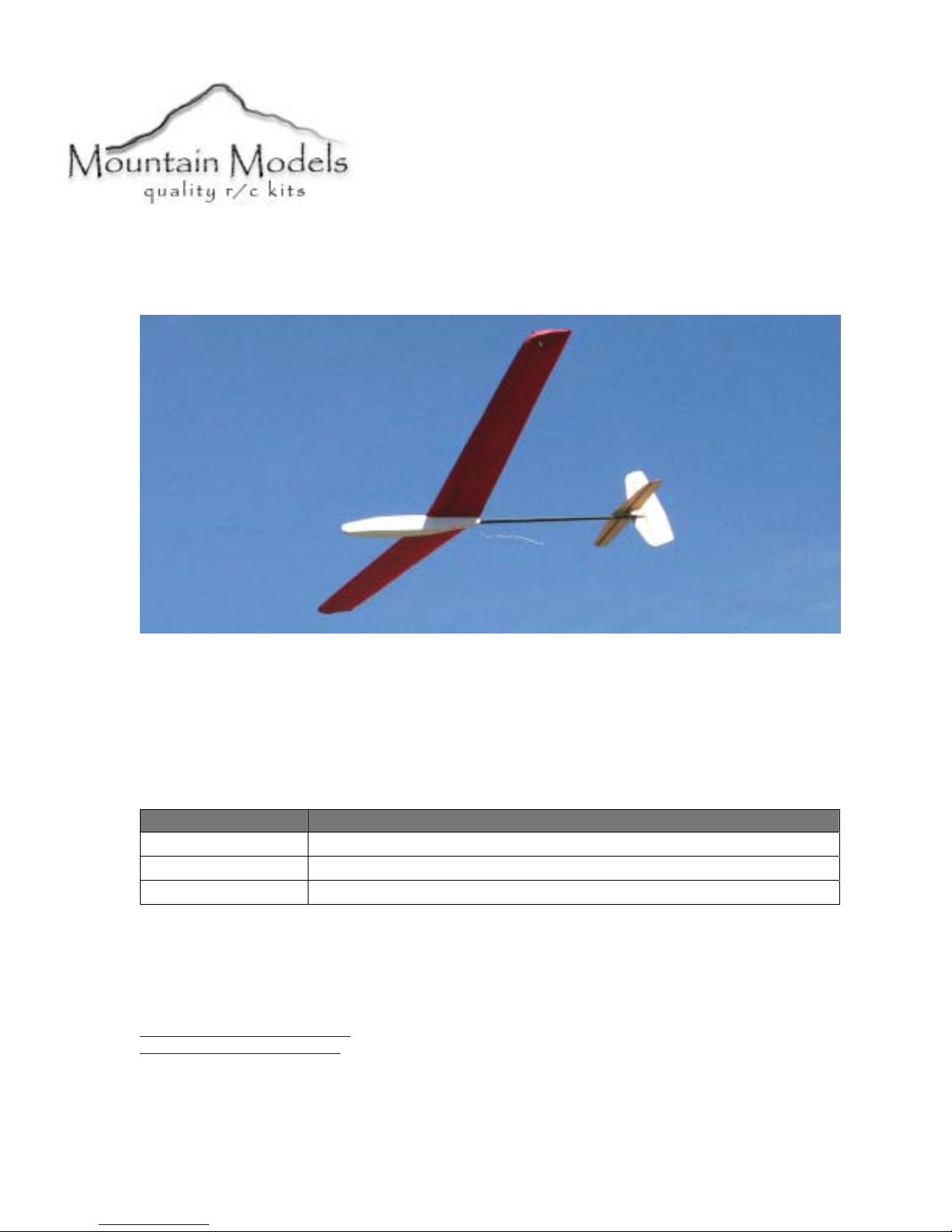
DL50 Discus Launch Glider
DL50 Specifications
Length: 39 in. (99 cm.)
Wingspan: 50in. (127 cm.)
Wing Area: 275in
Weight: 8oz. (227 g.)
2
(1774 cm
2
)
Revision History
Date Revision Notes/Comments
6/12/2004 Document initial creation.
8/18/2004 Changes to instructions
9/9/2004 Update to version 2
Thank you for purchasing the DL50. This plane is an elevator/rudder discus launch glider,
designed for the intermediate pilot who wants a strong, easy to build and fly glider. The DL50
was a joint design effort between Doug and Matthew Binder.
Sincerely, Mountain Models
Doug Binder 465 D Street
doug@mountainmodels.com
www.mountainmodels.com
Phone: 719.372.6727
P.O. Box 762
Penrose, CO 81240
Created by Ross Design Group for exclusive use by Mountain Models.
Before You Begin
Before you begin building your DL50 make sure you read and understand all of the
instructions thoroughly.
Additionally, you will need to have the following items. Check to make sure that all of your
parts are there and in good shape, and review a couple quick building tips to make this
whole process go quicker and easier.
What You Will Need
• Smooth and flat work surface
• Wax paper
• Thin Cyanoacrylate (CA) glue
• Foam Safe Glue – 5 minute epoxy or foam safe medium CA
• Minwax water based Polycrylic
• Hobby knife with #11 blades
• Needle nose pliers
• Wire cutters
• Sanding block with 200 grit sandpaper
• 2 channel radio
• 2 channel receiver
• 2 micro servos
• 4 cell 350 mAH NiMH battery pack
Parts List
Number
in Kit
Wire and Carbon Rods
1 26.5” tapered carbon boom
4 .060” carbon spars
2 .025” music wire pushrods
2 Pushrod tubes
Foam, etc
2 Foam wing sections
2 .7 oz Fiberglass
1 1.4 oz Fiberglass
Bagged Parts
1 6” heat shrink tubing
1 6” Velcro strip for mounting the battery and receiver
1 1/16” x 3/8” x 2” Launch Peg
1 12” Kevlar tow
1 1/2" x 64” carbon tape
4 8-32 wing hold down screw
1 8-32 self tapping screw
Description of Part
2
Mountain Models DL50

General Building Tips
• Balsa is a lightweight and fragile wood, so you do need to be careful with it;
however, you will also need to use a little bit of force to make everything fit
properly, so don’t be too timid.
• Join all of your wood pieces using thin CA (Cyanoacrylate) glue, unless we tell you
otherwise. In general, only a small amount of CA is necessary to glue parts together.
• Use only foam safe glue to attach the wing sections. Regular CA will dissolve the
foam.
• Don’t remove any pieces from the balsa sheets until they’re ready to be used. That
way, parts won’t get mixed up or disappear.
• After you remove pieces from the balsa sheets, carefully remove any of the extra
material from where the piece was attached.
• Don’t over force your pieces together. If they aren’t going together properly, make
sure you have the right pieces and that they are oriented correctly.
• If you want to remove the charred edges caused by the laser cutting process,
dampen a cloth with bleach and gently rub the affected areas. Removing the char
will not increase the strength but will make it look better.
Assembly Instructions
Okay, so now you are ready to actually build the DL50. If you follow these simple
instructions, we can have you flying in no time!
The Entire Process A to Z
Step 1: Prepare your workspace for assembly.
Step 2: Assemble the wings.
Step 3: Assemble the fuselage.
Step 4: Assemble and install the stabilizers, rudder, and elevator.
Step 5: Install the elevator and rudder servos.
Step 6: Finish the kit up with the battery, throws, and center of gravity.
Final Step: Go fly.
Step 1: Preparing Your Workspace for Assembly
Before you begin assembling the DL50, you must prepare your workspace.
Making space in what is probably the most crowded place in your home
1. Insure that your worktable is clean and flat.
2. Keep wax paper handy to prevent gluing the plane to the table.
Step 2: Assembling the Wing
The first thing you are going to assemble is the wing of your airplane. This involves shaping
the wingtips, gluing the spars, attaching the wing halves, covering, applying the
reinforcement, adding the launch peg support.
Mountain Models DL50
3
Shaping the wing
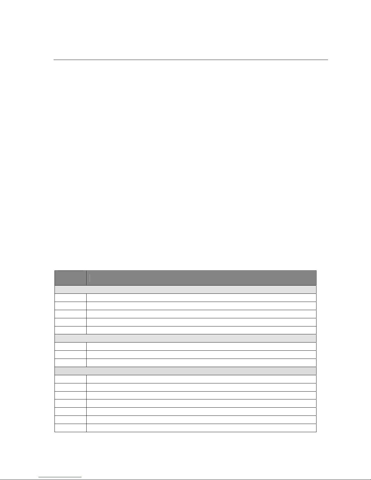
Carefully remove the two wing cores from the foam block. With a straight edge and a sharp
xacto, trim the trailing edge. The root chord is 6.25” and the tip chord is 4.75”.
We will now shape the wingtips. Using 220 grit sandpaper, shape the tips as shown. Take
care to get both tips the same.
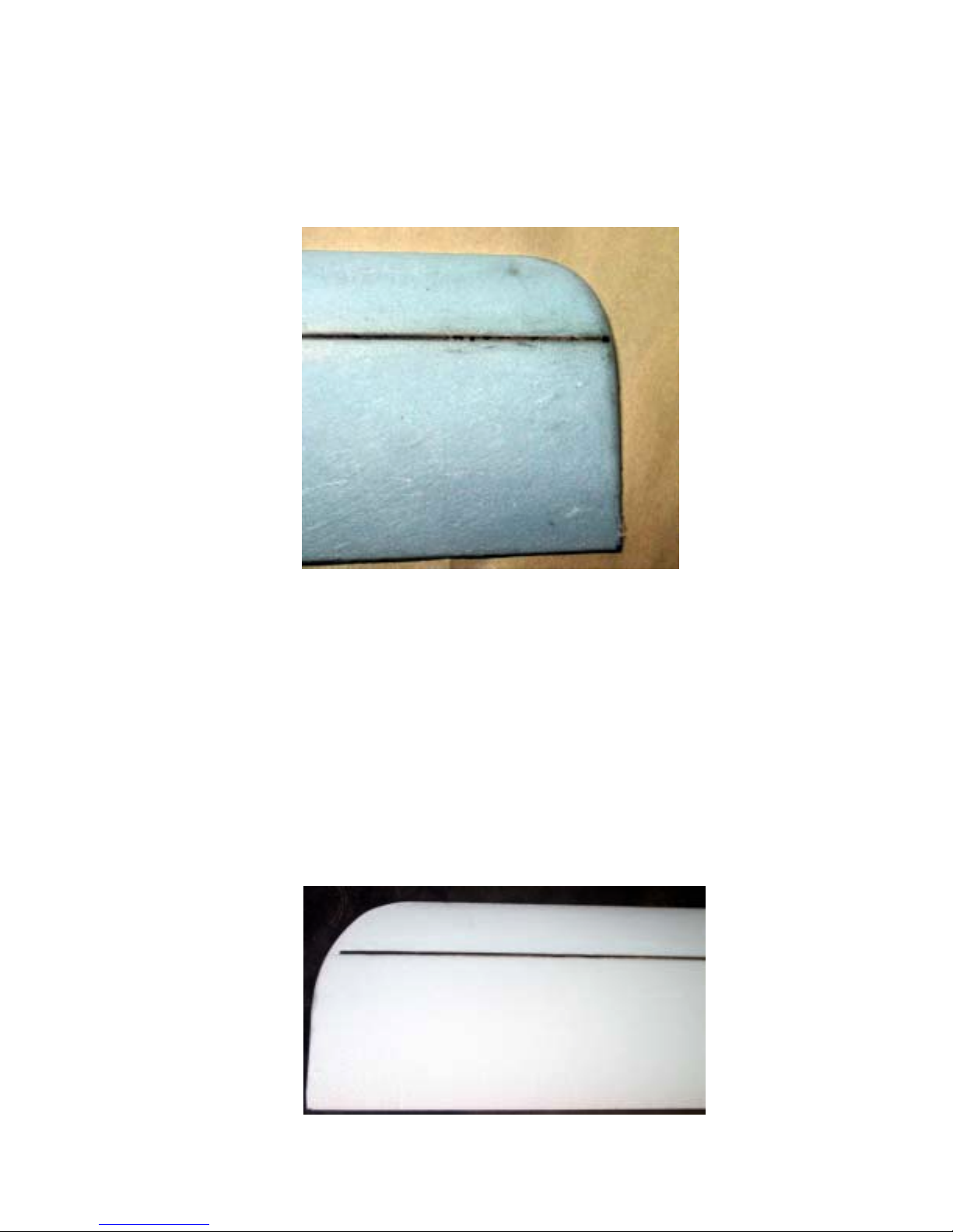
Installing the Spars
The spar is created by gluing in four .060” carbon fiber rods into the grooves in the wing
cores .
! Putting together the spar
1. Verify the spar rods fit properly in the grooves and that there are no foam beads in the
grooves left over from the foam cutting process.
2. Cut the rods to length and lightly sand the rods with fine sandpaper to remove any surface
coating. Note that the top spars are a different length than the bottom spars.
3. Glue the spars in place, one at a time. Don’t try to do more than one as you will be too
rushed. Mix up a small amount of 5 minute epoxy and lay it into a groove. Press a spar
into the groove and scrape off the excess epoxy. If you want to play it safe, use 30
minute epoxy. The wing core is on a flat surface, right? Lay wax paper over the epoxied
spar and gently press for a smooth finish.
4
Mountain Models DL50
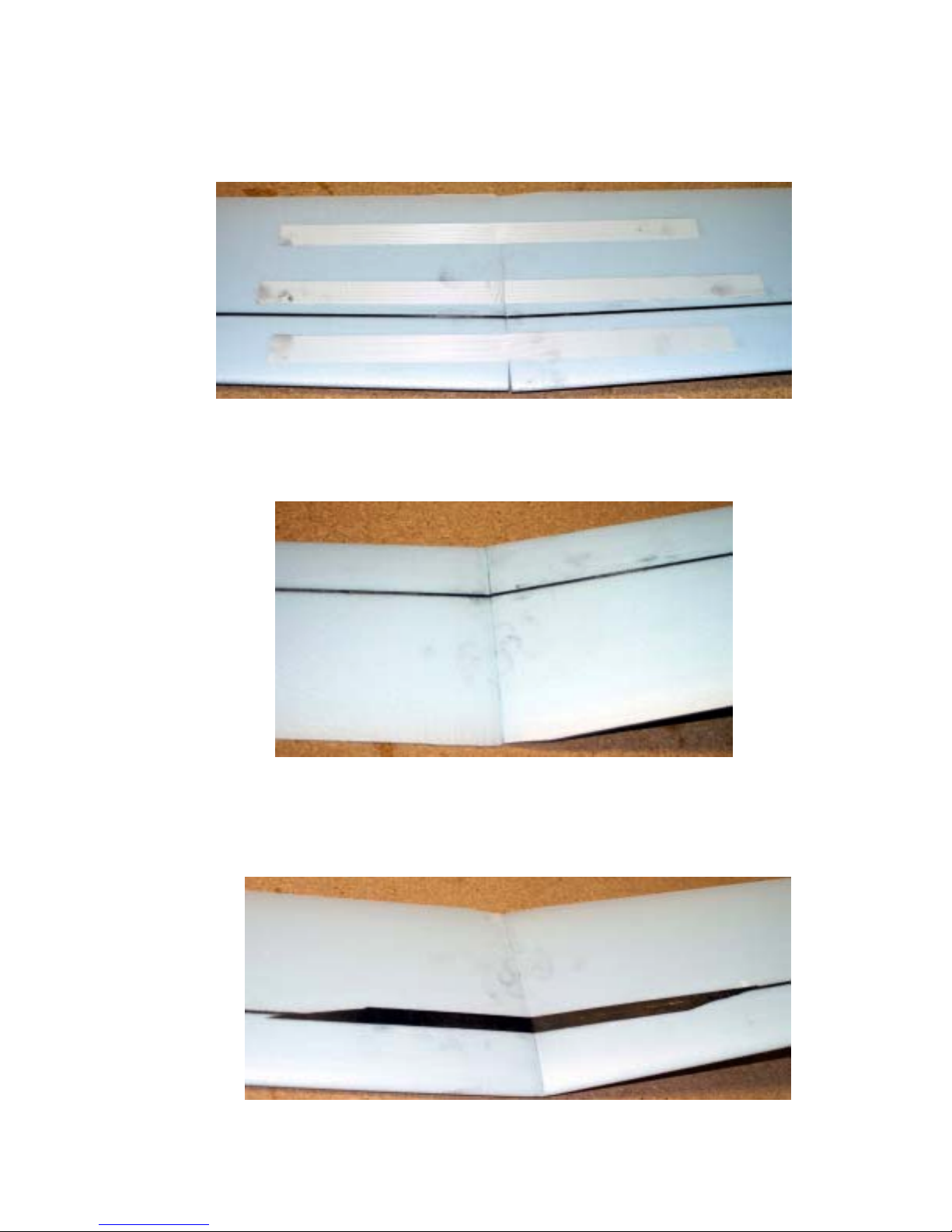
! Gluing the wing halves
4. Lay the two wing cores next to each other, bottom side up and centers touching. Run
three strips of tape across the center joint to hold the two halves together.
5. Flip the wing cores over, mix up a small amount of epoxy and flow the epoxy into the
center joint. Lift one wing to close the joint and force the epoxy out. The tip should be
approximately nine inches off the table. Wipe off the excess epoxy. Place something
under the raised wing to hold the wing up and let the glue dry. You may want to place a
weight on the wing against the table to keep it from lifting.
6. Cut two strips of ½” carbon fiber tape 12” long but cut at a sharp angle so that the ends
come to a point. This is to distribute the load over a larger area and not create a stress
riser. See the photo. Cut both ends this way.
7. Epoxy the strips to the top and bottom of the center joint. The easiest way to do this is to
lay the tape on a piece of wax paper and apply the epoxy to the tape. Lift off the tape and
place it on the wing joint. I like to line up the points with the spar rods.
Mountain Models DL50
5
 Loading...