


Expansion
Chassis
Operating Manual
Copyright
(C) 1982
Mountain Computer
Inc.
Manual Number
11-00166-03

_ab
e
of
Contents
Introduction
.••.••••.•••••••••••••••••••••••••.••••••
i
Chapter 1 --
Installation
What
You
~1eed
......••....
,.
.•......••..••••••.••.•.....
1-1
Unpa
cking
.•.
""
..••.•.•..•...•
"
.•.• " ...
G
••••••••
e
••••••
1-1
Packing
List
..........................................
1-2
Before
Plugging
In
••••••••••••••••••••••••••••••••••••
1-2
1-
2
1-
3
The
B 0 X
••• " •••••••••••••••••••••••••••••••••••
"
•••••••
The
Mother
Board
.....................................
.
The
Interface
Card
....................................
1-4
Interface
C
ard
Jumper
and
Switch
Posi
tioning .......... 1-6
pp 1
••••••••••••••••••••••••••••
...............
1-6
PP2
••
PP3
••
PP4
••
SW1
...
.
..................
1-6
.
.•.•..........
1-6
.
.....
........
" 1-7
.............................
1-7
The
50
Pin
Ribbon
Cable
...............................
1-7
The
Small
16
Installing
the
Plugging
Into
Pin
Ribbon
Interface
Cable
•••••••.•••••••••••••••••
1-8
Card
.........................
1-9
the
Apple
............................•..
1-9
Attaching
the
Power
Transformer
••••
Installing
Other
Peripheral
Cards
••
.
.....•..
1-
11
...•.••••
1-12
If
You
Are
Using
Pascal
• • • • • • • • • • • • • • • • • • • • • • • • • "
•••
1 - 1 2
The
Last
Steps
.•.•.•••.•.••.••.••..•.•....••••.••.•..
1-12
Multiple
Expansion
Chassis
...........................
1-12
The
P P 1
Jumper
.......................................
1-13
Multiple
Interface
Cards
.............................
1-13
Chapter 2 --
Operating
the
Expansion
Chassis
Select
or
Deselect
....................................
2-
Swi
tching
Modes
From
BASIC
or
the
Moni
tor
.............
2-2
Integer
BASIC
.........................................
2-2
Applesoft
BASIC
.................•......•..•....•......
2-3
The
Monitor
...........................................
2-3
Switching
Modes
From
Pascal
...........................
2-4
The
Software
Com
man
d s T a b 1 e
•••••••••••••••••••••••••••
2-
5
Some
Helpful
Tips
.....................................
2-6
Appendix A --
Installation
Considerations
Processors
Verses
Peripherals
.........................
A-1
Video
Cards
••••••••••••••••••••••••••••••••••.••••••••
A-1
Jumpers
to
the
Mother
Board
...........................
A-1
S e 1 e c t a b 1 e S 1 o t Ba n k s
•••••••••••••••••••••••••••••••••
A - 1
System
Configuration
Examples
•••••••••••••••••••••••••
A-2
Some
Ideal
Chassis
Peripherals
........................
A-
6
-
Table
of
Contents
(Continued)
Appendix B --
Trouble
Shooting
It
Doesn't
Work
At
All
•••••
·
~
••••••••••••••••••••••••••
B-1
The
Hardware
Select/Deselect
Button
Doesn't
Work •••
•••
B-1
Replacing
the
Fuse
....................................
B-1
Identifying
A
Blown
Fuse
••••••••••••••••••••••••••••••
B-2
The
Right
Fuse
For
the
Job
••••••••••••••••••••••••••••
B-2
Installing
the
New
Fuse
•••••••••••••••••••••••••••••••
B-3
If
the
Fuse
Repeatedly
Blows
••••••••••••••••••••
••••••
B-3
When
to
Send
It
Back
..................................
B-3
Appendix C --
Installation
Summary

CHAPrER
1
Chapter 1
INSTALATION
IN
STALLA'HO~
The
Expansion
Chassis
is
easy
to
install,
but
take
care
to
install
it
correctly.
The
directions
for
installing
your
Expansion
Chassis
appear
in
this
chapter
as
step
by
step
instructions.
If
you
follow
all
the
directions
in
this
chapter
carefully,
you
should
have
no
trouble
installing
the
Chassis
.
If
you
are
familiar
with
the
installation
procedure,
you
may
want
to
refer
to
the
brief
installation
summary
in
Appendix C
instead
of
rereading
this
entire
chapter.
However,
if
this
is
your
first
time
installing
an
Expansion
Chassis,
read
this
chapter
thoroughly
and
carefully,
following
all
the
instructions
as
you
read.
What
You
Need
To
use
your
Expansion
Chassis
you
need
only
an
Apple
II
or
II
Plus
.
All
Mountain
Computer
peripherals
and
many
other
well
designed
peripheral
cards
will
work
in
the
Expansion
Chassis.
For
information
on
installation
considerations
and
limitations
for
the
Expansion
Chassis,
see
Appendix A
in
this
manual.
An
optional
item
you
may
find
useful
is
an
IC
puller,
a
small
tweezer-like
device
used
to
remove
IC's.
You
can
probably
get
one
at
your
local
computer
or
electronics
store.
You'll
find
that
installing
the
Expansion
Chassis
is a little
easier
if
you
have
an
IC
puller,
but
you
don't
have
to
have
one.
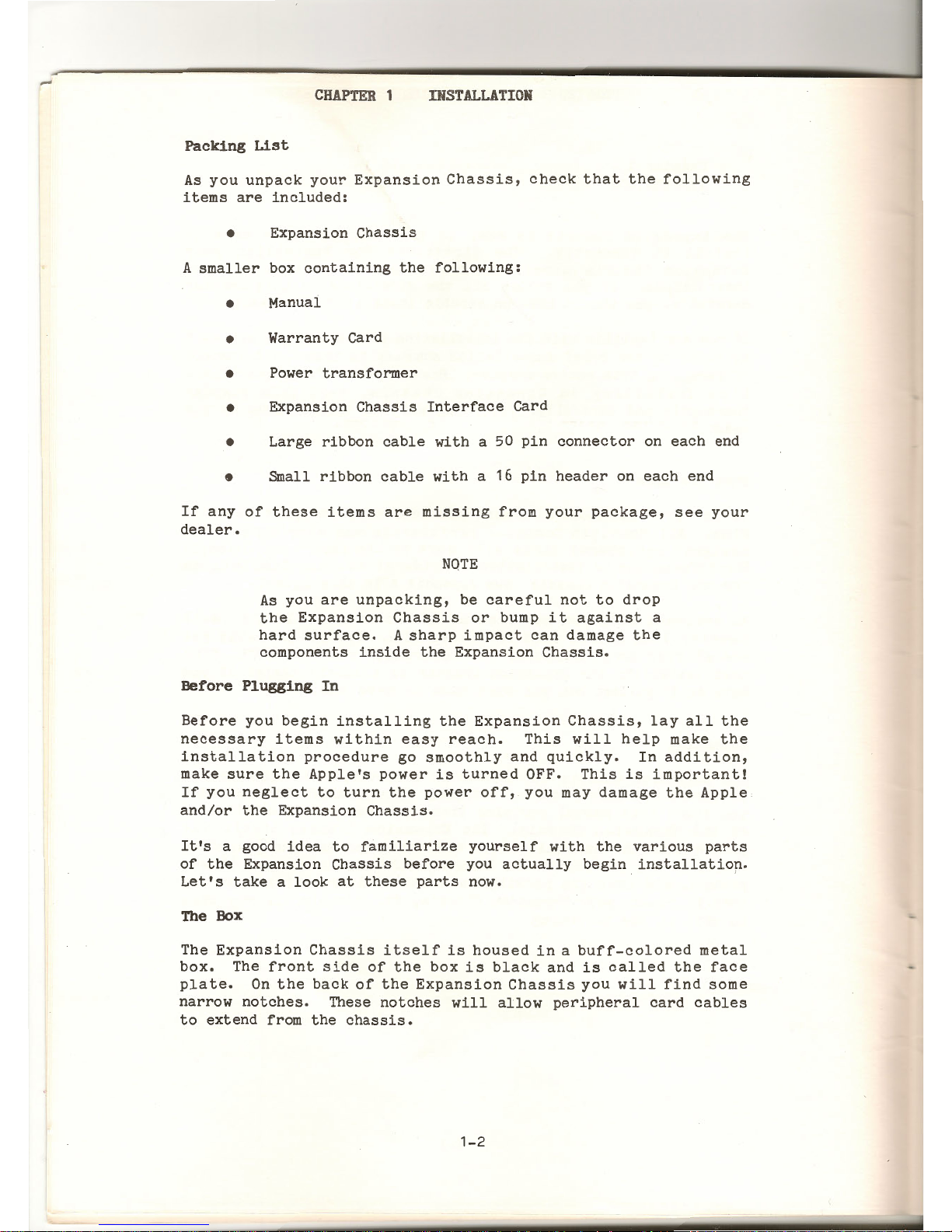
Unpacking
The
Expansion
Chassis
was packed
in a specially
designed
carton
to
insure
its
safety
during
shipping.
The
smaller
box
in
which
you found
this
manual
contains
items
necessary
for
installation
of
the
Expansion
Chassis.
The
Expansion
Chassis
itself
was
packed
beneath
the
smaller
box and
suspended
between
styrofoam
supports.
As
you
unpack
the
Expansion
Chassis
notice
how
it
was
packed,
and
save
the
packing
materials.
At
some
time
you
may
need
to
repack
your
Expansion
Chassis,
for
example,
if
you
wish
to
ship
it
for
servicing.
1-1
-
CHAPTER
1
INSTALLATION
Packing
List
As
you
unpack
your
Expansion
Chassis,
check
that
the
following
items
are
included:
•
Expansion
Chassis
A
smaller
box
containing
the
following:
•
Manual
•
Warranty
Card
•
Power
transformer
•
Expansion
Chassis
Interface
Card
•
Large
ribbon
cable
with
a 50
pin
connector
on
each
end
•
Small
ribbon
cable
with
a 16
pin
header
on
each
end
If
any
of
these
items
are
missing
from
your
package,
see
your
dealer.
NOTE
As
you
are
unpacking,
be
careful
not
to
drop
the
Expansion
Chassis
or
bump
it
against
a
hard
surface.
A
sharp
impact
can
damage
the
components
inside
the
Expansion
Chassis.
Before
Plugging
In
Before
you
begin
installing
the
Expansion
Chassis,
lay
all
the
necessary
items
within
easy
reach.
This
will
help
make
the
installation
procedure
go
smoothly
and
quickly.
In
addition,
make
sure
the
Apple's
power
is
turned
OFF.
This
is
important!
If
you
neglect
to
turn
the
power
off,
you
may
damage
the
Apple
and/or
the
Expansion
Chassis.
It's
a good
idea
to
familiarize
yourself
with
the
various
parts
of
the
Expansion
Chassis
before
you
actually
begin
installatiop.
Let's
take a look
at
these
parts
now.
The
Box
The
Expansion
Chassis
itself
is
housed
in a buff-colored
metal
box.
The
front
side
of
the
box
is
black
and
is
called
the
face
plate.
On
the
back
of
the
Expansion
Chassis
you
will
find
some
narrow
notches.
These
notches
will
allow
peripheral
card
cables
to
extend
from
the
chassis.
1-2
C
HAP'TEJi
~
JH3TAL
LATI
ON
As
you
face
the
front
of
the
Expansion
Chassis
you
will
see
on
the
right
edge
of
the
face
plate
two
LED
lights,
one
green
and
one
red,
and a square
shaped
black
button.
The
green
light
indicates
whether
the
Expansion
Chassis
is
powered
up,
and
the
red
light
indicates
whether
the
Expa
nsion
Chassis
is
selected.
The
button
is
used
to
select
and
deselect
the
Expansion
Chassis.
Remove
the
top
cover
of
the
Expansion
Chassis.
The
Expansion
Chassis'
cover
is
removed
in
much
the
same
way
as
the
Apple's.
Lift
the
back
edge
of
the
cover
at
the
middle
until
the
rear
fastener
pops
apart.
Then
slide
the
cover
backward
until
it
comes
free.
CAUTION
Make
sure
you
are
not
wearing
or
holding
any
metal,
such
as a ring
or a paper
clip,
on
your
hands
during
the
installation
procedure!
If
the
metal
touches
parts
of
the
power
supply
you
could
get a shock.
The
Mother Board
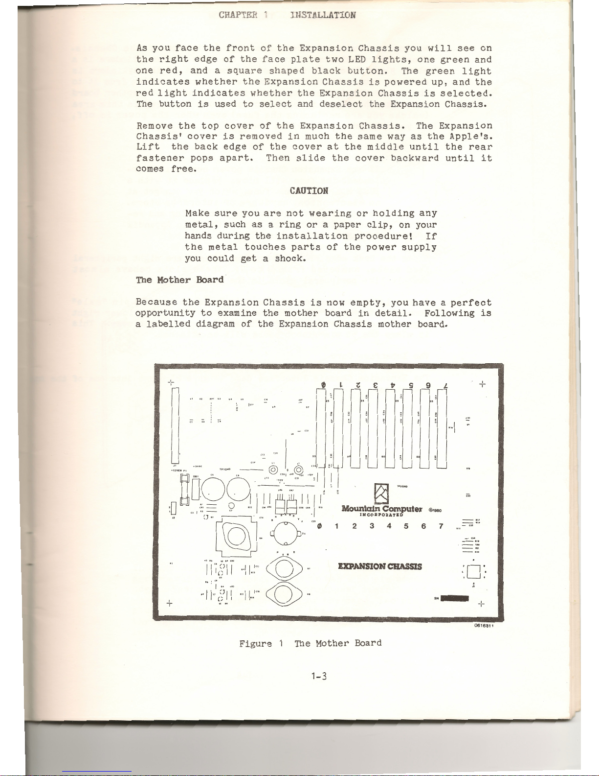
Because
the
Expansion
Chassis
is
now
empty,
you
have a perfect
opportunity
to
examine
the
mother
board
in
detail.
Following
is
a
labelled
diagram
of
the
Expansion
Chassis
mother
board.
+
I"
'
L_
'-----
'---
'-----
~
~
13]
TPOGIIO
c;,
Mountain Computer
©1
980
I
HCORPORATI
2 3
4
5
6
7
-
...
_.,,
EXPANSION
CHASSIS
·o·
. .
+
··-
-:-
0616811
Figu
r e 1 The
Mother Boa
rd
1-3
••
-
CHAPTER
1
INSTALLATION
Notice
the
twin
cylinders
near
the
left
edge
of
the
Chassis.
These
are
capacitors.
Directly
to
the
left
of
the
cylinders
is
a
clear
glass
fuse.
In
front
and
to
the
right
of
the
cylinders
is
a
short,
round,
black
transformer
with
wires
extending
from
it
to
the
mother
board.
The
components
in
this
area
of
the
mother
board
comprise
the
power
supply.
Do
not
touch
anything
in
this
area
(unless
you
are
replacing
the
fuse)
even
when
the
power
is
off,
or
you
may
get
an
electrical
shock.
NOTE
If
the
Expansion
Chassis
power
supply
is
over-
loaded,
the
fuse
will
blow.
Replace
it
with
a
BUSS
MDX
1-1/2
amp.
fuse,
which
you
can
get
at
an
electronics,
hardware
or
autoparts
store.
Detailed
instructions
on
identifying
and
re-
placing
a blown
fuse
can be found
in
Appendix
B
--
Trouble
Shooting.
Along
the
back edge
of
the
Expansion
Chassis
are
eight
peripheral
card
slots,
numbered
from 0 to
7.
These
slots
behave
almost
exactly
like
peripheral
slots
in
the
Apple.
In
the
left
rear
corner
of
the
mother
board
is a 50
pin
"male"
connector
labelled
"J1".
Notice
the
white
"1"
at
the
lower
right
edge
of
the
connector
and
the
"25"
at
its
upper
right
edge.
This
is
where
the
50
pin
ribbon
cable
will
be
attached.
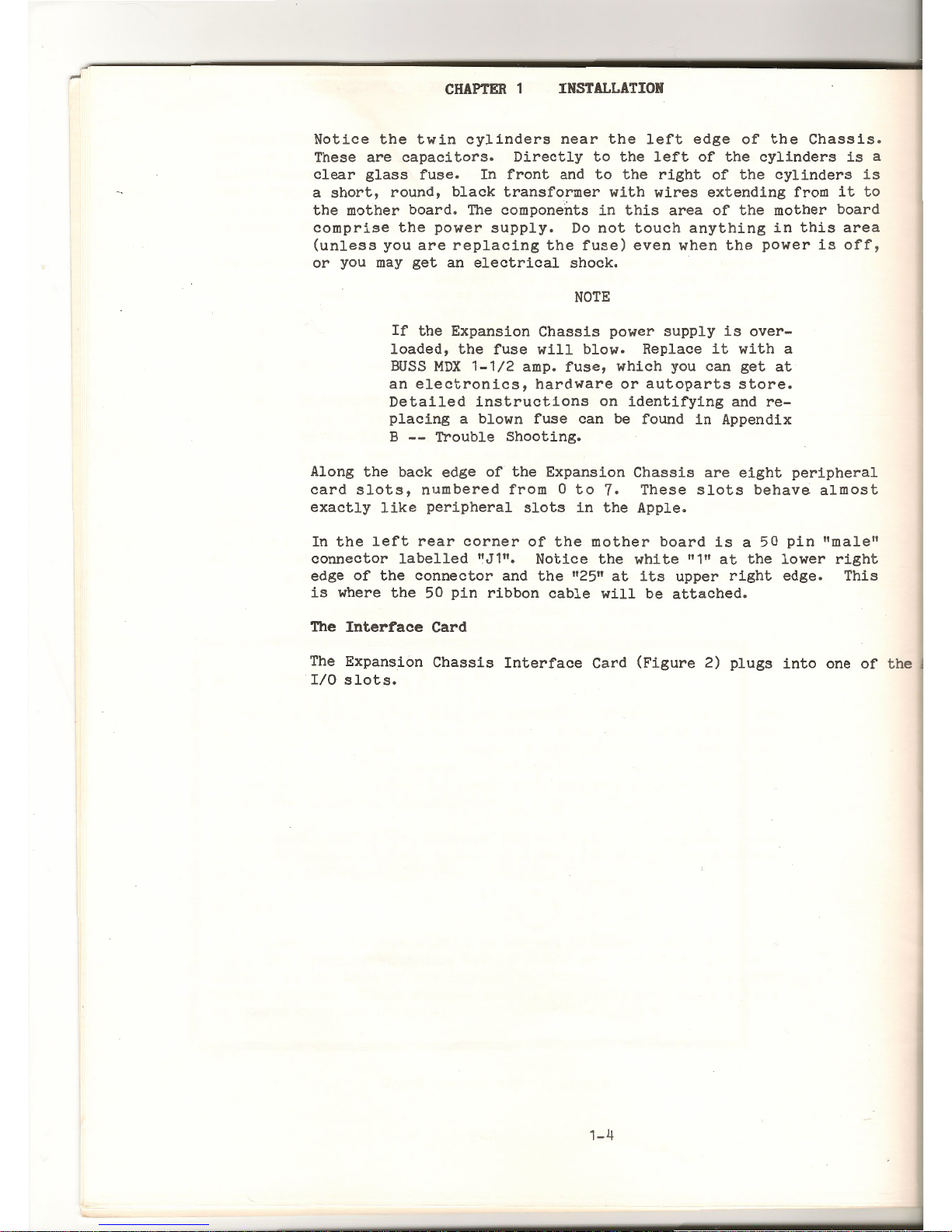
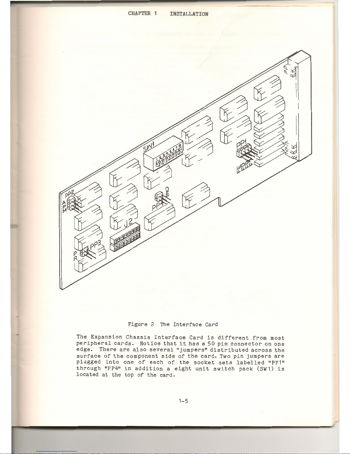
The
Interrace
Card
The
Expansion
Chassis
Interface
Card
(Figure
2)
plugs
into
one
of
the
I/0
slots.
1-4
CHAPTER
1
INSTALLATION
Figure
2
The
E
The
Int
xpans·
erface
c
periphe
1on
Chassi
ard
edge
ral
cards
s
Interfac
su
•
There
are • Not
ice
that
. e
Card
is
d.
rface
of
the
also
severa
"~
t
has a 50 7 ffe
rent
fr
~~
ugged
in
to
component
s . dl
Jumpers"
d .
p>n
co
nne c to
om
most
1
rough
"PP4"
~ne
of
each
1 :
of
the
card1stributed
ac r on
one
ocated
at
th
1n
additio
o
the
sock
• Two
pin
ju
ross
the
e
top
of
th
n a
eight
.
et
sets
lab
mpers
are
e
card.
un1t
switch
elled
"PP1"
pack
(SW1)
.
1S
1-5
CHAPTER
1
INSTALLATION
Interface
Card Jumper and
Switch
Positioning
The
following
paragraphs
describe
the
Expansion
Chassis
features
that
are
controlled
by
Jumper/Socket
sets
PP1
through
PP4
and
switch
pack
SW1.
PP1
Jumper/Socket
Set
PP1
(Figure
2)
allows
the
user
to
select
(or
deselect)
any
of
up
to
four
Expansion
Chassis,
via
soft-
ware.
It
selects
the
software
data
pattern
that
will
enable
the
Expansion
Chassis
associated
with
this
interface
card.
For
example,
if
the
jumper
is
placed
in
socket
FE
then
a
write
of
"FE"
to
location
C020-C02F
will
activate
the
Expan-
sion
Chassis
(writing
an
unused
pattern,
or a pattern
for
another
chassis
will
turn
this
chassis
off).
NOTE
Jumper/Socket
set
PP4
can
disable
this
software
select
feature.
The
setting
of
the
PP1
jumper
is
important
if
you
will
be
using
more
than
one
Expansion
Chassis
in a single
system.
PP2
CAUTION
Only
one
chassis
may
be
accessed
(via
software)
at a time.
If
two
Expansion
Chassis
have
the
PP1
jumper
in
the
same
socket
then
the
system
will
try
to
access
two
sets
of
peripherals
in
the
same
I/0
slots.
The PP2
Jumper/Socket
set
selects
whether
the
Apple
or
the
Expansion
Chassis
has
access
to
the
C800
through
CFFF
Apple
memory
locations.
The "A"
position
locks
the
C800
space
to
the
Apple.
The
"M"
position
dedicates
it
to
the
Expansion
Chassis.
The
"P"
position
allows
the
c8oo
space
to
be
used
by
the
software
selected
user.
PP3
The
PP3
Jumper/Socket
set
determines
whether
the
Apple
or
the
Expansion
Chassis
will
be
selected
after
the
Apple
RESET
key
has
been
pressed.
The "P"
position
allows
the
Apple
to
be
selected
during
power-up
only,
the
Expansion
Chassis
will
be
selected
if
the
RESET
key
is
pressed.
The "R"
jumper
position
selects
the
Apple
for
power-up and
RESET.
1-
6

CHAPTER
1
INSTALLATION
PP4
The PP4
Jumper/Socket
set
enables
or
disabes
the
PP1
fun-
ction.
The "E"
position
allows
the
user
to
write
to
the
C020
through
C02F
space
(cassette
memory
locations)
to
enable
or
disable
the
Expansion
Chassis.
The
"D"
position
will
disable
all
writes
to
the
C020
through
C02F
locations.
Only
the
Expansion
Chassis
switch
will
change
the
state
of
the
chassis.
SW1
Switch
pack
SW1
contains
eight
switches,
one
for
each
I/0
slot
in
the
Expansion
Chassis.
The
slots
associated
with
each
switch
are
as
follows:
1 =
Slot
0
3 =
Slot
2
5
=
Slot
4
1 =
Slot
6
2
=
Slot
1
4
=
Slot
3
6 =
Slot
5
8 =
Slot
1
If a switch
is
ON
it
locks
the
selected
Device
Select-I/O
Select
slot
address
ranges
to
the
Apple.
For
example,
if
SW1-2
is
placed
in
the
ON
position,
then
I/0
slot 1 in
the
Apple
is
always
enabled
and
the
Expansion
Chassis
slot 1 is
disabled.
Regardless
of
which
unit
is
selected.
The
50
Pin
Ribbon Cable
The
large
50
pin
ribbon
cable
that
came
with
your
Expansion
Chassis
is
for
attaching
the
Chassis
to
the
Expansion
Chassis
Interface
Card.
This
cable
has
two
50
pin
"female"
connectors,
one
on
each
end,
which
will
plug
into
the
50
pin
connectors
in
the
Expansion
Chassis
and
on
the
Expansion
Chassis
Interface
Card.
It
doesn't
matter
which
end
of
the
50
pin
ribbon
cable
is
plugged
into
the
Expansion
Chassis
and
which
into
the
Expansion
Chassis
Interface
Card.
However,
the
connectors
- on
the
cable
must
be
oriented
in a particular
way.
Each
pin
and
socket
in
each
connector
is
assigned
a number from 1
to
50.
It
is
important
to
plug
the
connectors
in
so
that
pin
number 1 is
plugged
into
socket
number 1.
If
the
connectors
are
plugged
in
the
wrong way,
neither
your
Apple
or
the
Expansion
Chassis
will
be damaged,
but
the
Expansion
Chas~is
will
not
work.
The
connectors
on
the
ribbon
cable
each
have a
white
triangle
in
one
corner,
which
points
to
socket
1.
The
colored
stripe
along
one
edge
of
the
cable
is
on
the
same
edge
as
socket
number
1.
These
markings
will
help
you
orient
the
cable
correctly.
As
indicated
earlier,
labels
indicating
pins
1 and 25
are
located
next
to
the
50
pin
connector
inside
the
Expansion
Chassis.
The
50
pin
connector
on
the
back
edge
of
the
Expansion
Chassis
Interface
Card
has
no
such
labels,
but
pin 1 is
in
the
bottom
corner
(next
to
the
gold
plated
peripheral
slot
connectors.)
1-7

.-
CHAPTER
1
INSTALLATION
'
First
plug
the
ribbon
cable
into
the
Expansion
Chassis
Interface
Card
(refer
to
Figure
3)
so
that
socket 1 on
the
cable
corres-
ponds
to
pin
1 on
the
Expansion
Chassis
Interface
Card.
The
red
stripe
and
the
white
triangle
should
be
at
the
bottom
edge
of
the
card.
Now
plug
the
other
end
of
the
ribbon
cable
to
the
connec-
tor
inside
the
Expansion
Chassis
so
that
pin 1 in
the
Chassis
is
plugged
into
socket
1 on
the
cable.
The
white
triangle
should
be
lined
up
with
the
pin 1 label
next
to
the
connector.
Check
that
the
red
stripe
is
toward
you
as
you
face
the
front
of
the
Chassis.
Check
the
connections
on
both
the
Expansion
Chassis
Interface
Card
and
the
Expansion
Chassis
to
make
sure
the
connectors
are
firmly
attached.
The
following
illustration
shows
the
correct
arrangement
of
the
Expansion
Chassis,
50
pin
ribbon
cable,
and
Expansion
Chassis
Interface
Card.
39731
Figure
3
50
Pin
Ribbon
Cable
Installed
The
Small
16
Pin
Ribbon Cable
One
end
of
the
16
pin
ribbon
cable
will
plug
into
the
IC
socket
labelled
"J2"
on
the
Expansion
Chassis
Interface
Card,
and
the
other
end
of
the
cable
will
plug
into
an
IC
socket
in
the
Apple's
mother
board.
As
with
the
50
pin
ribbon
cable,
it
is
important
that
pin
1 on
the
cable
correspond
to
pin
1 on
the
IC
socket.
1-8

CHAPTER
1
INSTALLATION
The
connectors
on
each
end
of
the
16
pin
ribbon
cable
are
marked
at
pin 1 to
make
installation
easier.
The
particular
mark on
the
c
onnectors
will
vary,
depending
on
the
cable
you
have.
Connectors
will
be
marked
with
either a dot,
arrow,
or a small
notch.
To
locate
pin 1 on
the
J2
socket,
lay
the
Interface
Card
so
that
the
component
side
is
facing
up and
the
Mountain
Computer
label
is
right
side
up.
When
the
Interface
Card
is
oriented
this
way,
pin
1 on
the
J2
socket
is
in
the
lower
left
corner.
Now
plug
the
16
pin
connector
into
the
J2
socket
so
that
the
mark
indicating
pin 1 corresponds
to
pin 1 on
the
J2
socket.
Check
that
the
connector
is
firmly
seated
in
the
socket
and
that
none
of
the
pins
are
bent.
The
next
section
will
tell
you
how
to
plug
the
16
pin
connector
into
the
Apple.
Installing
the
Inter~ace
Card
The
Expansion
Chassis
Interface
Card
can
be
plugged
into
any
Apple
slot
including
slot
#0
if
you
are
not
using
the
Apple
Language
System.
If
you
are
using
the
Apple Language
System,
the
Language
Card
must
be
plugged
into
the
Apple's
slot
#0,
and
the
Expansion
Chassis
Interface
Card
plugged
into
another
Apple
slot.
Because
Pascal
is a slot-dependant
language
there
are
limitations
on
its
use
in
conjunction
with
the
Expansion
Chassis.
For
now,
use
slot
#7
for
your
Expansion
Chassis
Interface
Card
if
you
are
using
Pascal.
(The
Pascal
slot
issue
will
be
discussed
in
detail
in
the
section
called
"If
You
Are
Using
Pascal
••• " later
in
this
chapter.)
If
you
are
not
using
Pascal,
any
Apple
peripheral
slot,
including
slot
#0,
will
work
equally
well.
Plugging
Into
the
Apple
It
is
easier
to
install
the
Expansion
Chassis
Interface
Card
if
you
temporarily
remove
all
other
peripheral
cards
from
the
Apple.
CAUTION
Make
sure
your
Apple
is
turned
OFF
before
you
remove
or
insert
anything!
Or
you
may
damage
the
the
Apple
and/or
the
Interface
card.
1-
9

-
CHAPTER
1
INSTALLATION
Plug
the
Expansion
Chassis
Interface
Card
into
the
slot
you
have
chosen.
Arrange
the
large
50-pin
ribbon
cable
so
that
it
passes
through
the
opening
with
the
built-in
strain
relief
on
the
rear
of
the
Apple's
case.
Make
sure
the
card
is
seated
firmly
and
is
plugged
all
the
way
in
the
slot.
If
the
card
is
not
properly
plugged
in,
your Apple
may
be damaged when you
turn
the
power on.
To
complete
installation
of
the
Expansion
Chassis
Interface
Card
you
must
remove an IC from
the
Apple's
mother
board
and
plug
the
Expansion
Chassis
Interface
Card's
small
ribbon
cable
into
the
empty
socket.
The IC
you
must
remove
is
the
third
one
from
the
right
in
row F,
immediately
to
the
right
of
the
large
IC
labelled
"ROM
D0
11
• (Look
along
the
left
edge
of
the
Apple's
mother
board
for
the
letter
labels
for
each
row.)
This
IC
is
number F12. The
following
photographs
(Figure
4)
show
the
IC's
position
in
the
Apple.
Figure
5 IC Removal
Notice
the
small
notch
on
the
edge
of
the
IC
that
is
closest
to
the
keyboard.
If
you
ever
wish
to
replace
this
IC, you
must
plug
it
in
so
that
the
notch
is
toward
the
keyboard.
Gently
remove
the
IC
by
sliding
the
edges
of
the
IC
puller
(or
your
fingernails)
under
it,
as
shown
in
the
photograph
above,
and
slowly
pulling
straight
up.
Be
careful
not
to
bend
the
pins
on
the
IC.
When
the
IC
has
been
removed,
label
it,
and
store
it
away
in a safe
place.
If
you
ever
wish
reconfigure
your
system
without
the
Expansion
Chassis,
you
will
need
to
replace
this
IC.
One
edge
of
the
16
pin
connector
on
the
free
end
of
the
small
ribbon
cable
is
marked
with a notch
or a dot.
Carefully
plug
the
connector
into
the
vacant
socket
so
that,
as
you
face
the
Apple
keyboard,
the
marked
edge
is
toward
the
front.
If
there
are
other
peripheral
cards
plugged
into
your
Apple,
thread
the
ribbon
cable
under
them.
1-10

CHAPTER
1
INSTALLATION
When
the
cable
has
been
plugged
in,
inspect
the
socket
to
make
sure
no
pins are
sticking
out.
(That's
what
happens
if
you
try
to
force
bent
pins!)
If
pins
are
sticking
out,
remove
the
connector,
carefully
straighten
the
pins,
and
repeat
the
plugging
in
procedure.
Following
is
an
illustration
of a correctly
installed
Expansion
Chassis
Interface
Card.
Figure
5
Correctly
Installed
Interface
Card
Attaching
the
Power Transformer
The
black
box
with
two
cords
extending
from
its
opposite
ends
is
a
power
transformer.
One
of
the
cords
has a socket
that
will
plug
into
the
Expansion
Chassis.
The
other
cord
plugs
into
an
ordinary
wall
outlet.
NOTE
DO
NOT
plug
the
power
transformer
into
the
wall
yet!
Plugging
the
power
transformer
into
the
wall
is
one
of
the
very
last
steps,
and
for
good
reason.
On
the
back
edge
of
the
Expansion
Chassis
is a plug
that
the
power
transformer
socket
will
attach
to.
Plug
the
power
transformer
connector
cord
into
the
E-xpansion
Chassis.
If
you
have
trouble
plugging
it
in,
it
may
be
backwards.
If
so,
turn
it
around
and
try
again.
1- 11

CHAPTER
1
INSTALLATION
Installing
Other
Peripheral
Cards
Now
you
are
ready
to
install
your
other
peripheral
cards.
With
15
slots
available,
you can
configure
your
system
in a variety
of
ways.
You
will
find
that
you
have
the
same
slot
freedom
in
the
Expansion
Chassis
that
you have
with
the
Apple.
That
is,
you
can
plug
peripheral
cards
into
any
slot
you
wish
except
slot
#0,
which
has
limitations.
Slot
#0
in
the
Expansion
Chassis
has
the
same
limitations
as
Apple's
slot
#0.
If
You
Are
Using
Pascal
••••
Pascal,
as
implemented
on
the
Apple
II,
is a slot-dependant
language.
This
means
that
Pascal
expects
certain
peripheral
slots
to
contain
only
certain
types
of
peripherals.
For
example,
with
the
Pascal
System
slot
#1
can
only
contain
a
printer
or
other
similar
output
device.
The
Last
Steps
If
you
have
followed
all
the
directions
in
this
chapter
so
far,
you
are
now
ready
to
complete
the
last
installation
steps.
These
steps
are
the
same
no
matter
what
system
configuration
you
are
using.
Replace
the
Expansion
Chassis
top
cover
•.
Slide
the
cover
into
place
and
press
on
the
rear
corners
until
the
fasteners
snap
together.
The
remaining
step
is
to
plug
the
Expansion
Chassis
power
transformer
into a grounded
electrical
outlet.
If
you
are
using
more
than
one
Expansion
Chassis
make
sure
each
power
transformer
is
plugged
in.
Multiple
Expansion
Chassis
Each
Expansion
Chassis
must
be
connected
to
an
Expansion
Chassis
Interface
Card,
which
must
be
plugged
into
an
Apple.
You
can't
use
one
Expansion
Chassis
Interface
Card
for
more
than
one
Expansion
Chassis.
You
cannot
plug
an
Expansion
Chassis
Inter-
face
Card
into
an
Expansion
Chassis,
the
Chassis
will
not
work.
If
you
are
using
more
than
one
Expansion
Chassis
with
one
Apple,
you
will
need
to
reset
the
PP1
jumpers
on
the
Expansion
Chassis
Interface
Cards
for
every
additional
Chassis
you
install.
By
setting
the
PP1
jumpers
you can
determine
exactly
which
data
bit
will
select
which
Chassis.
1-1 2

CHAPTER
1
INSTALLATION
The
PP1
Jumper
If
you
examine
the
PP1
jumper
socket
closely
(Figure
2),
you
will
see
that
it
is
divided
into
four
possible
jumper
positions.
Each
position
represents
a
different
setting,
and
each
setting
is
labelled
with a silk
screened
hexadecimal
number
at
the
bottom
of
the
socket.
You
must
change
the
PP1
jumper
settings
so
that
each
Expansion
Chassis
uses a different
one.
We
recommend
that
you
use
the
following
settings
for
your
Chassis.
o
first
Chassis
FE
o
second
Chassis
FD
o
third
Chassis
FB
o
fourth
Chassis
F7
The
PP1
jumpers
are
all
set
at
position
F7
at
the
factory.
One
Expansion
Chassis
can
be
left
at
this
setting,
but
the
others
must
be changed.
To
change
the
PP1
jumper
setting,
you
must
move
the 2 pin
jumper
to a different
position.
Carefully
remove
the
jumper
by
pul
ling
it
straight
out
of
the
connector
(DON'T
BEND
THE
PINS).
Plug
it
into
the
position
you
have
chosen.
Change
the
PP 1
jumper
set-
tings
for
each
additional
Expansion
Chassis,
using a different
setting
each
time.
Multiple
Interface
Cards
Now
you
are
ready
to
plug
the
Expansion
Chassis
Interface
Cards
into
the
Apple.
One
Expansion
Chassis
Interface
Card
should
be
installed
exactly
as
described
in
the
section
that
appears
earlier
in
this
chapter,
called
"Plugging
In".
The
other
Expansion
Chassis
Interface
Cards
are
a
little
simpler
to
install.
Additional
Expansion
Chassis
Interface
Cards
don't
require
the
16
pin
ribbon
cable.
(When
installing
them,
omit
the
steps
in
which
you
attach
the
ribbon
cable
to
the
Expansion
Chassis
Interface
Card
and
plug
the
ribbon
cable
into
the
Apple's
mother
board.)
Simply
plug
these
Interface
Cards
into
the
peripheral
slot
you
have
chosen.
1-
13


,
J
CHAPTER 2 OPERATING
THE
EXPANSION CHASSIS
Chapter 2
OPERATING
THE
EXPANSION
CHASSIS
Your
Expansion
Chassis
should
now
be
fully
installed
and
ready
to
use.
To
turn
on
your
Expansion
Chassis,
turn
on
the
Apple.
The
Expansion
Chassis
power
supply
turns
on
or
off
when
it
senses
that
the
Apple
has
been
turned
on
or
off.
The
Expansion
Chassis
will
not
receive
any power
unless
the
Apple
is
turned
on.
Software
that
works
with
the
Apple
II,
including
Pascal
programs,
should
work
with
the
Expansion
Chassis.
However, you
may
wish
to
enhance
the
Expansion
Chassis'
usefulness
by
customizing
your
software
to
make
the
most
of
the
additional
peripheral
slots.
Select
and
Deselect
The
Expansion
Chassis
can
be
in
either
select
mode
or
deselect
mode.
Switching
back
and
forth
between
these
conditions
allows
you
to
alternate
between
the
peripheral
slots
in
the
Apple
and
those
in
the
Chassis.
When
the
Expansion
Chassis
is
deselected,
the
Apple's
peripheral
slots
are
selected.
That
is,
if
you
refer
to
slot
#4,
the
peripheral
card
in
the
Apple's
slot
#4
will
respond.
When
the
Expansion
Chassis
is
selected
and
you
refer
to
slot
#4,
the
peripheral
card
in
the
Chassis'
slot
#4
will
respond.
NOTE
This
is
generally
true,
however
SW 1 switch
5
(refer
to
Chapter
1)
can
override
this
feature.
PP4
can
also
disable
this
feature.
Many
peripherals
require
access
to
the
Apple
C800
space,
the
PP2
jumper
may
be
set
to
the
P
position
and
access
can
be
selected
via
software.
The
current
mode
of
the
Expansion
Chas-
sis
is
indicated
by
the
two
lights
on
the
Chassis
faceplate.
The
green
light
indicates
that
the
power
is
on
(i.e.
the
Chassis
is
properly
installed
and
the
Apple
is
turned
on).
The
red
light
indicates
that
the
Expansion
Chassis
is
selected.
When
the
Expansion
Chassis
is
first
turned
on,
only
the
green
light
should
go
on,
indicating
that
the
power
is
on
but
the
Chassis
is
deselected.
NOTE
If
the
front
panel
lamps
(green
and
red)
are
on,
and
the
Apple
will
not
operate
properly
then
the
50-pin
ribbon
cabl e
may
be
improperly
installed.
Refer
to
Chapter 1 for
install-
ation
information.
2
-1

CHAPTER 2 OPERATING
THE
EXPANSION
CHASSIS
There
are
two
ways
to
change
the
Expansion
Chassis'
mode.
The
simplest
method
is
to
press
the
black
button
on
the
face
plate
below
the
green
and
red
lights.
When
you
do
this,
the
red
light
comes
on,
indicating
that
the
Expansion
Chassis
is
selected.
Pressing
the
button
again
causes
the· red
light
to
go
off,
indicating
that
the
Chassis
is
deselected.
You
can
switch
modes
with
this
button
at
any
time.
NOTE
Pressing
the
button
while
software
is
being
executed
may
cause
your
software
to
behave
unpredictably.
It
is
often
more
convenient
to
switch
the
Expansion
Chassis'
modes
through
software.
The
exact
method
for
switching
modes
through
software
depends on
the
computer
language
you
are
using.
The
following
sections
present
the
software
commands
for
selecting
and
deselecting
the
Expansion
Chassis.
CAUTION
Use
of
the
cassette
port
when
the
Expansion
Chassis
is
connected
to
the
system
i s
not
recommended. The
Expansion
Chassis
select/de
-
select
software
uses
the
cassette
port
ad-
dress.
Use
of
this
software
address
does
not
interfere
with
the
normal
operation
of
the
Apple
system
(cassette
pl~yer
disconnected.)
Connection
of a cassette
recorder
(or
any
device)
to
this
port,
will
cause a device
conflict
during
cassette
record
or
playback
operations.
If
the
cassette
port
must
be
used,
set
the
PP4
jumper
to
the D position.
Switching
Modes
From
BASIC
or
the
Monitor
If
you
are
using
Integer
BASIC,
Applesoft
BASIC,
or
the
Monitor,
switching
the
Expansion
Chassis
from
mode
to
mode
is
simply
a
matter
of
inserting
a
value
into a memory
location.
This
can
easily
be
done
either
in
immediate
execution
mode
or
from
a
program.
Integer
BASIC
To
select
the
Expansion
Chassis
from
Integer
BASIC,
simply
type
the
command
POKE
-16352,254
The
red
light
on
the
Expansion
Chassis'
face
plate
will
then
come
on
to
indicate
that
the
Chassis
is
selected.
2-2

CHAPTER 2 OPERATING
THE
EXPANSION
CHASSIS
This
command
only
selects
an
Expansion
Chassis
with a PP1
jumper
setting
of
FE.
If
you
are
using
more
than
one
Expansion
Chassis,
you
can
select
the
Chassis
with
other
PP1
settings
by
replacing
the
254
in
this
command
with
one
of
four
other
values.
See
the
Software
Commands
Table
later
in
this
chapter
for a list
of
the
values
you
must
use
.
To
deselect
the
Expansion
Chassis
from
Integer
BASIC,
type
POKE
-16352,255
and
the
red
light
will
go
off,
indicating
that
the
Chassis
is
deselected.
If
you
are
using
more
than
one
Expansion
Chassis,
this
command
will
deselect
all
of
them.
To
deselect
just
one
Chassis
of
several,
use
the
above
command
to
deselect
all
of
them. Then
reselect
only
the
Chassis
you want.
Applesoft
BASIC
Controlling
the
Expansion
Chassis
from
Applesoft
is
almost
exactly
like
the
Integer
BASIC
procedures.
To
select
the
Expansion
Chassis
from
Applesoft,
type
POKE
49184,254
As
with
Integer
BASIC,
you
can
select
Chassis
with
other
PP1
settings
by
replacing
the
254
with
another
value.
See
the
Software
Commands
Table
for a list
of
these
values.
To
deselect
the
Expansion
Chassis
from
Applesoft,
type
POKE
49184,255
This
command
will
deselect
all
the
Chassis
plugged
into
your
Apple.
To
deselect
one
of
several
Expansion
Chassis,
first
use
this
command
to
deselect
them
all,
and
then
reselect
the
one you
want.
The
Monitor
To
select
the
Expansion
Chassis
from
the
Monitor,
type
C020:FE
As
with
both
versions
of
BASIC,
the
hexadecimal
value
FE
in
this
statement
will
have
to
be
replaced
if
you
are
using
Expansion
Chassis
with
different
PP1
settings.
You
will
find
the
appropriate
values
with
which
to
replace
the
FE
in
the
Software
Commands
Table.
To
deselect
the
Expansion
Chassis
from
the
Monitor,
type
C020:FF
2-3

CHAPTER 2 OPERATING
THE
EXPANSIOH
CHASSIS
If
there
are
more
than
one
Expansion
Chassis
installed
in
your
Apple,
this
command
will
deselect
them
all.
To
deselect
one
of
several
Expansion
Chassis,
first
deselect
them
all
with
the
command
above, and
then
reselect
the
one you want.
Switching
Hodes
From
Pascal
Selecting
or
deselecting
the
Expansion
Chassis
from
Pascal
is
a
little
different
from
doing
the
same
thing
from
BASIC
or
the
Monitor.
There
is
no
single
command
to
access a particular
memory
location.
However, embedding two
short
Pascal
procedures
in
your
program
will
allow
you
to
select
or
deselect
your
Chassis
from
Pascal.
The
two
Pascal
procedures
are
given
below.
The
first
procedure,
when
called
in
a program,
selects
the
Expansion
Chassis.
The
second
procedure
deselects
it.
Neither
of
these
procedures
require
parameters.
Here's
the
Select
procedure:
PROCEDURE
EXCHON;
CONST
EXPANCH:-16352;
SELECT:254;
TYPE
MEMORY=PACKED
ARRAY 0 •• 0 OF 0 ••
255;
VAR
ADDR:INTEGER;
P:
MEMORY;
BEGIN
ADDR:
=EX
PANCH;
MOVELEFT(ADDR,P,2);
P 0 ::SELECT
END;
This
procedure
will
only
select
an Expansion
Chassis
with a PP1
jumper
setting
of
FE.
If
you
are
using
more
than
one
Expansion
Chassis,
you
can
modify
this
procedure
slightly
to
select
your
other
Chassis
by
replacing
the
value
in
the
third
line
of
the
procedure,
SELECT=254;,
with a different
value.
The
values
you
must use
are
given
in
the
Software
Commands
Table.
2- 4

CHAPTER 2 OPERATING
THE
EXPANSION
CHASSIS
Here's
the
Deselect
procedure:
PROCEDURE
EXCHOFF;
CONST
EXPANCH:-16352;
DESELECT=255;
TYPE
MEMORY=PACKED
ARRAY 0 •• 0 OF
0 •• 255;
VAR
ADDR:INTEGER;
P:
MEMORY;
BEGIN
ADDR::EXPANCH;
MOVELEFT(ADDR,P,2);
P 0
:=DESELECT
END;
If
you
are
using
more
than
one
Expansion
Chassis,
this
procedure
will
deselect
all
of
them.
To
deselect
one
of
several
Expansion
Chassis,
first
deselect
all
of
them
with
the
above
procedure,
and
then
reselect
the
one you want
with
the
Select
procedure.
NOTE
These
procedures
will
not
work
by
themselves.
As
with
all
Pascal
procedures,
they
must
be
incorporated
in
a program and
compiled.
The
Software
Commands
Table
The
following
table
shows
all
the
commands
discussed
in
this
chapter.
This
table
assumes
that,
if
you
are
using
more
than
one
Chassis,
you
arranged
their
PP1
jumpers
as
suggested
in
this
manual.
2-5

CHAPTER 2 OPERATING
THE
EXPANSION
CHASSIS
Table
1
Software
Commands
SELECT
DESELECT
-------------------------------------------------------------
Integer
BASIC
Chassis
1
Chassis
2
Chassis
3
Chassis
4
All
Chassis
Applesoft
BASIC
Chassis
1
Chassis
2
Chassis
3
Chassis
4
All
Chassis
The
Monitor
Chassis
1
Chassis
2
Chassis
3
Chassis
4
All
Chassis
Pascal
Chassis
1
Chassis
2
Chassis
3
Chassis
4
All
Chassis
POKE
-16352,254
POKE
-16352,253
POKE
-16352,251
POKE
-16352,247
POKE
49184,254
POKE
49184,253
POKE
49184,251
POKE
49184,247
C020:FE
C020:FD
C020:FB
C020:F7
SELECT:254
SELECT=253
SELECT=251
SELECT:247
Some
HelpfUl
Tips
POKE
-16352,255
POKE
49184,255
C020:FF
DESELECT=255
As
you
use
your Expansion
Chassis,
you
will
find
that
it
is
good
for
more
than
just
adding
peripheral
slots.
There
are
some
things
you
can
do
with
an
Expansion
Chassis
that
you
just
couldn't
do
with
an Apple,
no
matter
how
many
peripheral
slots
it
had.
For example,
if
you have a
hard-copy
print
routine
that
insists
your
printer
be
in
slot
#1, you can
switch
between two
different
printers
without
modifying
your
software.
If
you have,
say
both
a
dot
matrix
and a
letter
quality
printer,
you
can
plug
one
into
slot
#1
in
the
Apple and
the
other
into
slot
#1
in
the
Expansion
Chassis
and
switch
between
the
two
by
deselecting
or
selecting
the
Expansion
Chassis
at
strategic
points
in
the
program's
operation.
2
-6

CHAPTER 2 OPERATING
THE
EXPANSION
CHASSIS
Here's
another
idea.
If
you
have
an
Auto
Start
ROM
you
can
autoboot
disk
drives
plugged
into
the
Expansion
Chassis
by
simply
holding
in
the
Select/Deselect
button
on
the
Chassis
face
plate
while
you
turn
the
Apple on.
Another
way
to
autoboot
disk
drives
in
the
Expansion
Chassis
is
to
press
the
RESET
key.
If
you
discover
some
clever
ways
to
use
the
Expansion
Chassis,
we
at
Mountain
Computer
would
love
to
hear
about
them
in
writing.
2- 7


APPENDIX A INSTALLATION
CONSIDERATIONS
Appendix A
Installation
Considerations
Your
Expansion
Chassis
is a useful
and
versatile
enhancement
to
your
Apple
II
computer
system.
Every
computer
product
designed
to
be
used
with
the
Apple
has
limitations
simply
because
there
are
so
many
products
available
for
the
Apple,
and
thus
many
possible
system
configurations.
This
section
on
limitations
of
the
Expansion
Chassis'
use
has
been
included
in
the
manual
so
that
you
can
get
the
most
from
your
Chassis.
Processors
verses
Peripherals
Some
peripheral
cards
are
also
microprocessor
cards.
For
this
reason,
a
few
may
not
work
in
the
Expansion
Chassis.
However,
you
can
use
processor
cards
in
conjunction
with
your
Expansion
Chassis
by
always
plugging
them
into
the
Apple.
Video Cards
If
a
video
card
is
active
in
your
Apple
and
you
select
the
Expansion
Chassis
your
system
may
"hang",
and
you
may
have
to
power
down
the
Apple
to
recover.
To
avoid
this
problem,
set
the
appropriate
SW1
switch
to
lock
out
the
Expansion
Chassis
for
the
Apple
slot
that
has
the
video
card.
NOTE
You
may
have
to
dedicate
the
Apple C800
space
to
Apple
use
only
(most
video
cards
use
the
C800
space).
This
is
done
by
placing
the
PP2
jumper
in
the A position.
Jumpers
to
the
Mother Board
Any
peripheral
card
with a jumper
that
plugs
into
the
Apple's
mother
board
should
be
plugged
into
the
Apple,
not
the
Expansion
Chassis.
In
most
cases
the
cable
connecting
the
peripheral
card
to
the
Apple's
mother
board
is
not
long
enough
to
reach
from
the
Expansion
Chassis
to
the
Apple.
Even
if
the
cable
is
long
enough,
it
is
inconvenient
to
have
unnecessary
cables
and
wires
stretched
between
the
Apple and
the
Chassis.
Selectable
Slot
Banks
The
Expansion
Chassis
doesn't
just
augument
your
Apple's
periph-
eral
capacity
with
eight
additional
peripheral
slots.
Instead
you
get
another
bank
of
slots.
For
example,
with a single
Chas-
sis
system
you
will
have
two
banks
of
peripheral
slots.
The
SW1
switches
allow
the
user
to
use
both
the
Apple
and
the
Expansion
Chassis
slots
at
the
same
time
(as
long
as
there
are
no
conflicts
(i.e.
two
cards
in
the
same
slot
and
the
SW1
switch·is
off).
A-1

APPENDIX A IN
STA
LLATI
ON
CONSIDERATIONS
One
advantage
to
this
scheme
is
that
slot
designations
in
your
software
apply
to
either
the
Apple
or
the
Expansion
Chassis,
depending
on
whether
the
Expansion
Chassis
is
selected
or
deselected
This
lets
you
switch
back
and
forth
between
two
similar
peripherals
(such
as
two di
sk
drives)
by
simply
selecting
and
deselecting
the
Expansion
Chassis.
System
Configuration
Examples
The
following
examples
demonstrate
a few
of
the
possible
system
configurations
that
can
be
setup
when
the
Expansion
Chassis
is
connected
to
the
Apple.
Example 1
CP/Mtm
CONFIGURATION
APPLE
I/0
SLOTS
0 - Language Card*
(MCI
RAMPLUS+
etc.)
-
Optional
2 -
Optional
3 - 80 Column
Card:*
4 - Z80
Softcard*
5 -
Optional
6 -
Disk
Controller*
7 -
Expansion
Chassis
Interface
EXPANSION
CHASSIS
I/0
SLOTS
0 -
None
-
Printer Interface
2 -
Modem
Interface
3 -
None
4 -
None
5 -
Optional
6 -
None
7 -
Optional
*
Set
SW 1 switches
1,
4,
5,
and 7 to
ON
(disables
Expansion
Chassis
slots
0,
3,
4,
and
6).
**
Set
the
PP2
jumper
to A (lock
C800
to
Apple).
A-2

APPENDIX A INSTALLATION
CONSIDERATIONS
Example
2
allocates
the
CP/M
environment
to
the
Expansion
Chassis
(the
Z80
Softcard
must
reside
in
the
apple).
This
allows
the
Apple
to
be
used
for
the
non-CP/M
environment.
Example 2
CP/Mtm
(EXTERNAL
CONSOLE)
CONFIGURATION
------------------------------------------------------------------
APPLE
I/0
EXPANSION
CHASSIS
SLOTS
I/0
SLOTS
0 -
Optional
0 -
Language Card
(MCI
RAMPLUS+
etc.)
1 -
Expansion
Chassis
1 -
Parallel
Printer
Interface
Interface
(viaMCICPS
Card
Phantom
slot)
2 -
Optional
2 -
Remote
Interface
3 -
Optional
3
-
MCI
CPS
Card
(Serial
Console
Interface)
4 -
Optional
4 -
Optional
5 -
Optional
5 -
Optional
6 -
Disk
Controller*
6 -
None
7 -
Z80
Softcardtm*
7 -
None
Interface
*
Set
SW1
switches
7 and 8
to
ON
(disables
Expansion
Chassis
slots
6 and
7).
A-3

APPENDIX A INSTALLATION
CONSIDERATIO
NS
Example
3
PASCAL
CONFIGURATION
------------------------------------------------------------------
APPLE
I/0
SLOTS
0 - Language Card*
(MCI
RAMPLUS+
etc.)
-
Optional
2 -
Optional
3 -
80
Column
Card:*
4-
Optional
5 -
Optional
6 -
Disk
Controller*
7 - Expansion
Chassis
Interface
EXPANSION
CHASSIS
I/0
SLOTS
0 -
None
-
Printer
Interface
2 -
Modem
Interface
3 -
None
4 - Optional(MCI Music
System
PWA I etc.)
5 -
Optional
(MCI
Music
System
PWA
II
etc.)
6 -
None
7 -
Optional
*Set
SW1
switches
1 ,and 7
to
ON
(disables
Expansion
Chassis
slots
0,
and
6).
**
Set
the
PP2
jumper
to A (lock
C800
to
Apple).
A-4

APPENDIX A INSTALLATION
CONSIDERATIONS
Example 4
CP/Mtm -PASCAL
COMBINATION
CONFIGURATION
APPLE
I/0
EXPANSION
CHASSIS
SLOTS
I/0
SLOTS
0 -
Language Card*
0 -
None
(MCI
RAMPLUS+
etc.)
1 -
Expansion
Chassis
1 -
Optional
Interface
2 -
Optional
2 -
Optional
3 -
80
Column
Card**
3 -
Optional
4 -
Optional
4 -
Optional
5 -
Optional
5 -
Optional
6 -
Disk
Controller*
6 -
None
7 -
Z80
Softcardtm
7 -
Optional
*
Set
SW1
switch
7
to
ON
(disables
Expansion
Chassis
slot
6).
**
Set
the
PP2
jumper
toP
(software
select
C800
space).
A-5

APPENDIX
A
INSTALLATION
CONSIDERATIONS
Some
Ideal
Chassis
Peripherals
Following
is a list
of
peripherals
that
are
especially
convenient
to
use
from
the
Expansion
Chassis.
This
list
is
just
a
small
sample
to
give
you a
general
idea
of
the
types
of
peripherals
that
work
well
in
the
Expansion
Chassis.
As
you
use
your
Expansion
Chassis
you
will
find
that
many
other
peripherals
work
equally
as
well
as
those
mentioned.
Mountain
Computer
Products
tm
The
Clock
SuperTalkertm
MusicSystemtm
ROMPLUS+tm
A/D
+ D/Atm
Introl
X-1otm
ROMWRITE~tm
RAMPLUS+
m
CPS
Multifunctiontm
Other
Products
Corvustm Hard
Disk
Systems *
Micromode'
IItm
*
Speechlink
m *
alphaSyntauri
Keyboardtm *
Passport
Designs
Keyboardtm *
In
General
Serial
or
parallel
cards
Disk
drives
NOTE
Because
of
their
design
some
types
of
perip
h-
eral
cards
don't
work
as
well
when
installed
in
the
Expansion
Chassis.
If
you
find
that
one
of
your
peripherals
doesn't
seem
to
work
well
when
plugged
into
the
Expansion
Chassis,
try
installing
it
in
the
Apple.
* These
are
trademarks
for
the
following:
Micromedemtm
for
Hayes
Microcomputer
Products,
Speechlinktm
for
Hueristics
Inc.,
Corvustm
for
Covrus
Systems
Inc.,
alphaSyntauritm
for
alphaSyntauri
Inc.,
Passport
Designstm
for
Passport
Designs
Inc.
A-6
-
--------------------

APPENDIX
B
Appendix B
Trouble
Shooting
TROUBLE
SHOOTING
Even
though
your
Expansion
Chassis
was
carefully
designed
and
built
with
quality
materials,
you
may
have a
problem
with
it
at
some
point.
You
can
solve
some
of
these
problems
yourself.
Other
problems
need
the
attention
of
experts
. The
purpose
of
this
section
of
the
manual
is
help
you
determine
which
kind
of
problem
you
have
, and
if
possible,
help
you
solve
it
yourself
.
It
Doesn't
Work
At
All
If
the
lights
on
Expansion
Chassis'
faceplate
do
not
come on and
the
Chassis
doesn't
respond
to
commands,
one
or
more
critical
cables
may
have
come
loose.
Turn
the
Apple
OFF
and
unplug
the
Chassis.
Then
check
that
•
the
power
transformer
is
properly
attached
to
the
Chassis
.
•
the
50
pin ribbon
cable
is
firmly
attached
to
the
Chassis.
•
the
50
pin
ribbon
cable
is
firmly
attached
to
the
Interface
Card.
If
all
the
cables
seem
firmly
attached,
but
the
Chassis
still
doesn't
work,
see
the
section
in
this
Appendix
called
"Replacing
the
Fuse".
The
Select/Deselect
Button
Doesn't
Work
If
software
will
control
the
Expansion
Chassis,
but
the
lights
on
the
faceplate
don't
go on and
the
button
doesn't
work,
the
block
that
holds
the
lights
and
Select/Deselect
button
may
have
come
loose. First
turn
the
Apple
OFF,
and
unplug
the
Chassis
from
the
wall
. Then remove
the
Expansion
Chassis'
top
cover.
Inside
the
Chassis
in
the
right
front
corner
is a small
block
that
holds
the
lights
and
button
on
the
Chassis
faceplate.
Check
that
the
wires
connecting
this
block
to
the
Chassis'
mother
board
are
secure.
Replacing
the
Fuse
Perhaps
the
most
likely
problem
to
occur
is
a blown
fuse.
If
you
are
careful,
you
should
never
have
to
replace
the
fuse
. However,
replacing
the
fuse
is
not
difficult
or
complicated.
The
fuse
in
the
Expansion
Chassis
acts
as a safety
device
.
If
something
goes
wrong and
the
electrical
current
in
the
Chassis
is
greatly
disturbed,
the
fuse
will
blow
out,
breaking
the
electrical
circuit
and
thus
saving
the
Expansion
Chassis'
power
supply
from
severe
damage.
B-1

APPENDIX
B
TROUBLE
SHOOTING
Here
are
some
reasons
that
the
fuse
might
blow
out:
e A
peripheral
card
is
not
properly
plugged
into
the
Chassis.
e A
defective
peripheral
card
is
plugged
into
the
Chassis.
•
Metal,
such
as a paper
clip
or
ring,
comes
in
contact
with
the
power
supply.
•
Liquid
is
spilled
inside
the
Chassis.
You
can
reduce
the
likelyhood
of a blown
fuse
by
avoiding
the
situations
listed
above.
Identifying
a Blown Fuse
The
most
obvious
indication
that
you
may
have a blown
fuse
is
if
the
Expansion
Chassis
will
not
work.
If
the
fuse
is
blown,
the
green
a~d
red
lights
on
the
Chassis
faceplate
will
not
work and
the
Chassis
will
not
respond
to
any commands.
NOTE
Before
you
run
out
to
buy
a new
fuse,
make
sure
that
the
Apple
in
which
the
Expansion
Chassis
is
plugged
is
on
and
the
Expan
sion
Chassis
itself
is
plugged
in
to
the
wall.
This
may
sound
silly,
but
check
anyway. It
might
save
you
time
and money.
If
the
Expansion
Chassis
seems
to
be
hooked
up
correctly
and
it
still
doesn't
work, you
should
check
the
fuse.
Before
you remove
the
Chassis'
top,
unplug
it
from
the
~all.
This
is
important!
If
you
touch
parts
of
the
power
supply
while
the
Chassis
is
plugged
in,
you
may
get a shock,
and
the
fuse
will
probably
blow
out
if
it
hasn't
already.
Remove
the
Chassis'
top
cover
and
examine
the
fuse.
(If
you
don't
remember where
it
is,
see
the
drawing
of the
mother
board
in
Chapter
1
of
this
manual.)
A
healthy
fuse
of
this
type
is
completely
clear.
If
the
fuse
is
blown
it
may be
slightly
discolored.
If
the
fuse
is
not
discolored
that
doesn't
necessarily
mean
it
is
not
blown,
however.
To
check
for
certain,
hold
the
fuse
gently
between
your
thumb and
forefinger,
and
pull
it
out.
Then
look
for
the
thin
wire
that
runs
through
its
length.
If
this
wire
is
broken,
the
fuse
is
definitely
blown.
The
Right
Fuse
For
the
Job
If
you
have
determined
that
your
Expansion
Chassis
does
need
a
new
fuse,
go
to
your
local
electronics,
hardware,
or
autoparts
store
and buy a
BUSS
MDX
1-1/2
amp.
fuse.
B-2

APPENDIX B TROUBLE
SHOOTING
Installing
the
Hew
Fuse
The new
fuse
is
easy
to
install.
Just
push
it
gently
into
the
metal
holders
the
old
fuse
was
in,
making
sure
the
metal
ends
of
the
fuse
come
into
contact
with
the
metal
holders.
Don't
worry
about
installing
it
backwards.
This
fuse
doesn't
have
a
backwards.
If
the
Fuse
Repeatedly
Blows
If
the
Expansion
Chassis'
fuse
blows
repeatedly,
one
of
the
peripheral
cards
plugged
into
the
Chassis
may
be
faulty
or
installed
improperly.
Try
removing
all
the
peripheral
cards
and
then
selecting
the
Expansion
Chassis.
If
the
fuse
no
longer
blows,
the
problem
was
probably
caused
by a
faulty
or
poorly
installed
peripheral
card.
If
the
fuse
continues
to
blow when
all
the
peripheral
cards
are
removed,
your
Expansion
Chassis
is
probably
not
working
properly.
In
this
case,
you
will
have
to
return
it
to
us
for
service.
See
the
section
in
this
appendix
called
"When
to
Send
It
Back"
for
details
on
returning
your
Expansion
Chassis
for
service.
When
to
Send
It
Back
Your
Expansion
Chassis
is
under
warranty
for 1 year,
and
we
at
Mountain
Computer
Inc.
are
happy
to
service
it
for
you
free
of
charge
during
this
time.
However,
if
you
want
your
Expansion
Chassis
to
be
serviced,
it
must
be
shipped
PREPAID
to
us.
Shipping
your
Expansion
Chassis
takes
time
and
money,
not
to
mention
the
possibility
that
it
may
be damaged
if
it
is
not
very
carefully
packed.
To
avoid
these
inconveniences
when
possible,
as
well
as
to
speed
up
the
time
it
takes
to
service
your
Chassis,
we
recommend
that
you
try
to
isolate
any
problems
you
are
having
before
you
send
your
Expansion
Chassis
to
us.
If
your
Expansion
Chassis
is
not
working
properly,
first
check
that
the
problem
isn't
one
that
you
can
take
care
of
with
the
information
in
this
appendix.
If
it
isn't
mentioned
here,
you
will
probably
have
to
send
your
Expansion
Chassis
to
us
for
service.
NOTE
Before
returning
your
Expansion
Chassis
to
us
for
repair,
contact
our
Customer
Service
department
for
an
authorization
number. Your
Expansion
Chassis
must
be
sent
prepaid.
See
the
warranty
in
the
back
of
this
manual
for
more
information.
B-3


APPENDIX
C
INSTALLATION
SUMMARY
Appendix C
INSTALLATION
SUMMARY
If
you
have
never
installed
an
Expansion
Chassis
before,
carefully
read
Chapter
1,
Installation,
following
the
instructions
as
you
read.
If
you
already
know
how
to
install
an
Expansion
Chassis,
you
can
skip
Chapter
1,
as
this
short
summary
probably
has
all
the
information
you need.
Following
is a list
of
installation
steps.
For
more
details,
refer
to
Chapter
1.
1)
Unpack
the
Expansion
Chassis
and
lay
all
parts
out
within
easy
reach.
2)
Attach
the
50
pin
ribbon
cable
to
the
Chassis
and
to
the
Interface
Card.
Make
sure
that
socket 1 corresponds
to
pin 1 at
each
end.
Plug
the
cable
in
so
that
the
colored
stripe
is
toward
the
front
of
the
Chassis
and
toward
the
bottom
edge
of
the
Interface
Card.
3)
If
you
want
to
change
the
PP1
- PP4
jumpers,
and
the
SW1
switch
positions,
do
so
now
(For
multiple
Chassis
systems,
change
the
PP1
jumper).
4)
Attach
the
smaller
16
pin
ribbon
cable
to
the
Interface
Card.
Make
sure
pin 1 on
the
cable
corresponds
to
pin 1 on
the
IC
socket.
Pin
1 on
the
ribbon
cable
connector
is
ma~ked.
5)
Remove
the
IC
at
location
F12
on
the
Apple
mother
board
(row
F,
third
IC from
the
right).
6)
Plug
the
Interface
Card
into
the
Apple.
Then
plug
the
free
end
of
the
smaller
16
pin
ribbon
cable
into
the
socket
on
the
Apple
mother
board
that
is
now
empty.
7)
Plug
the
tran
sfo
rmer
into
the
connector
on
the
rear
of
the
Expansion
Chassis.
8)
Replace
the
Expansion
Chassis'
top
cover,
and
plug
the
power
transformer
into
an
electrical
outlet.
C-1


 Loading...