

Page 1
[1]
User Guidelines – TCU-90L 12-06-2019 Vers. 003
_________________________________________________________________
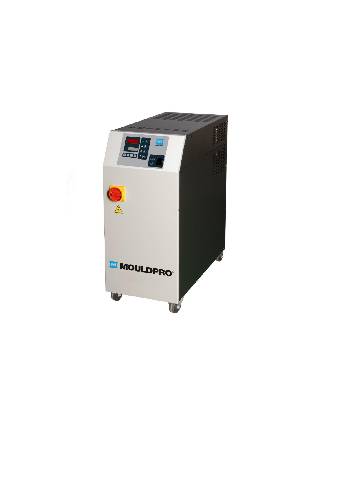
User Guideline
Temperature control unit TCU-90L
_________________________________________________________________
Page 2

[2]
User Guidelines – TCU-90L 12-06-2019 Vers. 003
General information
This documentation is copyrighted. Unauthorized duplication is prohibited by law. To
the best of our knowledge and belief, the information contained in this documentation
is true and correct as of the date of publication. The contents, however, do not
constitute a binding obligation on the part of MOULDPRO APS and are subject to
change without notice.
© Copyright 2019 MOULDPRO APS
Page 3

[3]
User Guidelines – TCU-90L 12-06-2019 Vers. 003
Contents
1 Indhold
2 GENERAL SAFETY INFORMATION ............................................................................................................................... 5
2.1 SAFETY SYMBOLS ................................................................................................................................................................ 5
2.2 RANGE OF APPLICATION ...................................................................................................................................................... 5
2.3 INTENDED USE ..................................................................................................................................................................... 5
2.4 SAFETY INFORMATION .......................................................................................................................................................... 6
2.4.1 General Information ...................................................................................................................................................... 6
2.4.2 Process Monitoring ....................................................................................................................................................... 6
2.4.3 Information for Operators and Personnel................................................................................................................... 6
2.4.4 Changing the Parameters ............................................................................................................................................ 7
2.4.5 Residual risks ................................................................................................................................................................. 7
2.5 USING THIS DOCUMENTATION.............................................................................................................................................. 8
2.5.1 Additional Documentation ............................................................................................................................................ 8
3 OVERVIEW TEMPERATURE CONTROL UNIT ............................................................................................................. 9
3.1 FRONT VIEW .......................................................................................................................................................................... 9
3.2 REAR VIEW.......................................................................................................................................................................... 10
3.3 IDENTIFICATION OF RESIDUAL RISK ON THE UNIT ............................................................................................................... 11
4 TECHNICAL SPECIFICATIONS ..................................................................................................................................... 12
5 INSTALLATION ................................................................................................................................................................ 13
5.1 INSTALLING AND DIMENSIONS OF THE TEMPERATURE CONTROL UNIT .............................................................................. 13
5.2 CONNECTIONS .................................................................................................................................................................... 14
5.3 POWER SUPPLY .................................................................................................................................................................. 15
5.4 INITIAL OPERATION - FILLING .............................................................................................................................................. 16
5.5 PUMP ROTATION CHECK ..................................................................................................................................................... 16
5.6 DISPLAY OF PUMP PRESSURE ............................................................................................................................................ 16
6 OPERATIONS................................................................................................................................................................... 16
6.1 OVERVIEW .......................................................................................................................................................................... 17
LEDS PROCESS INFORMATION AND START PUMP. ...................................................................................................... 18
7 DISPLAY AND PARAMETER SETTINGS ..................................................................................................................... 19
8 ALARM DISPLAY ............................................................................................................................................................ 21
9 STANDARD PCB SETTINGS. ........................................................................................................................................ 22
9.1 ADVANCED PARAMETER SETTINGS .................................................................................................................................... 24
10 LEAK MONITORING ........................................................................................................................................................ 30
10.1 DEACTIVATE LEAK MONITORING ........................................................................................................................................ 31
11 CONFIGURABLE RELAYS ............................................................................................................................................. 32
12 DESCRIPTION PCB CARD CONNECTORS ................................................................................................................. 34
13 MAINTENANCE ................................................................................................................................................................ 34
13.1 INSPECTION ........................................................................................................................................................................ 35
13.2 CLEANING ........................................................................................................................................................................... 35
Page 4

[4]
User Guidelines – TCU-90L 12-06-2019 Vers. 003
13.3 REPAIR ............................................................................................................................................................................... 35
14 OUT-OF-SERVICE / TRANSPORT ................................................................................................................................ 36
15 DISPOSAL ........................................................................................................................................................................ 36
16 WATER QUALITY ............................................................................................................................................................ 37
17 ELECTRICAL DIAGRAM ................................................................................................................................................ 38
18 WATER CIRCUIT DIAGRAM ........................................................................................................................................ 39
19 CONTROL CIRCUIT DIAGRAM .............................................................................................................................................. 40
19 COMPONENTS AND SPARE PART LIST ...................................................................................................................... 41
Page 5
[5]
User Guidelines – TCU-90L 12-06-2019 Vers. 003
2 General Safety Information
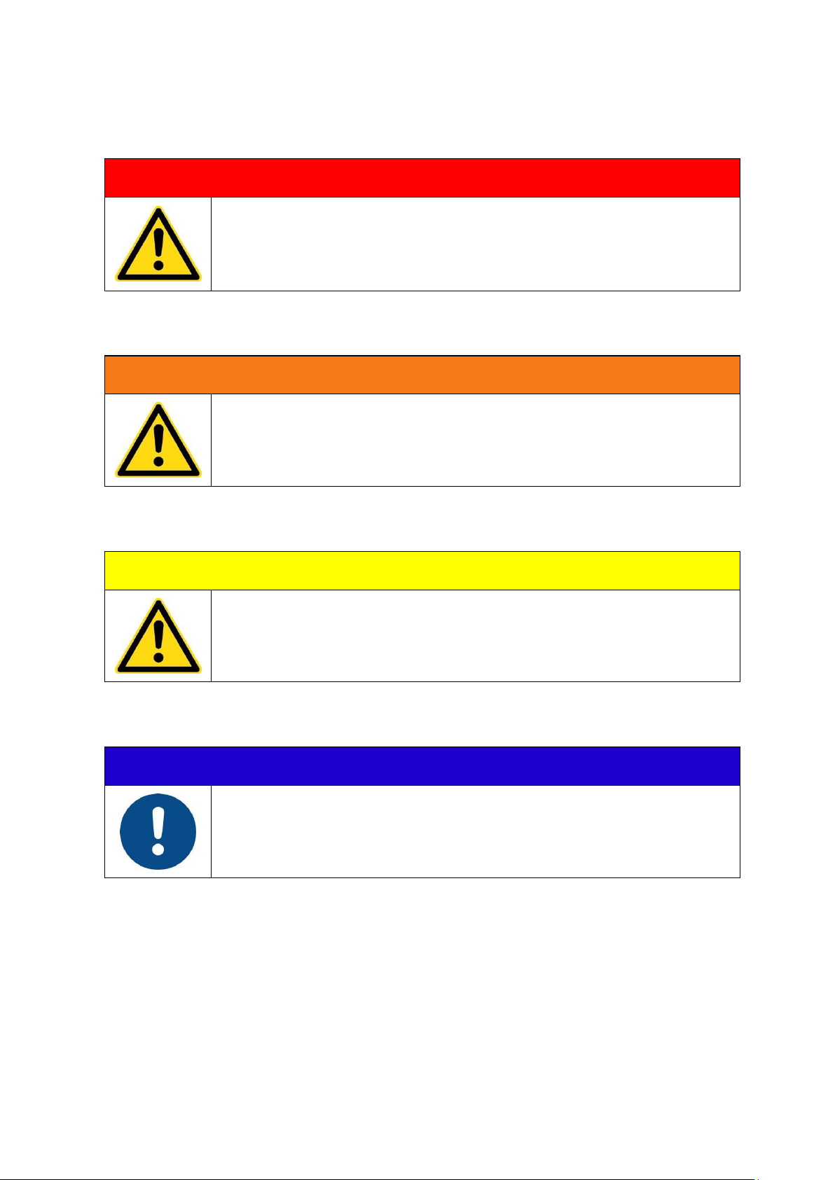
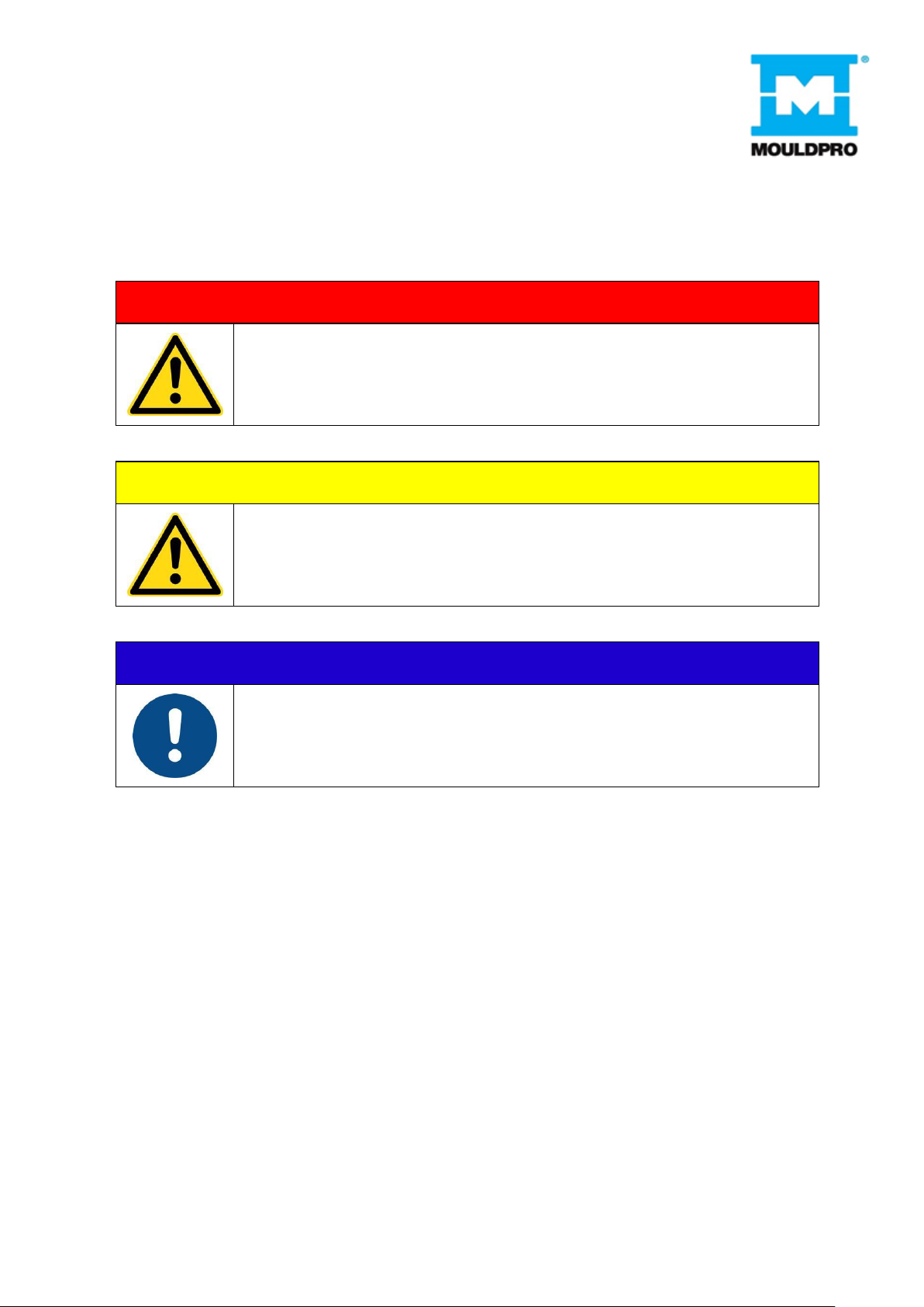
2.1 Safety Symbols
DANGER
Denotes imminent danger.
Failure to heed the information can result in death or grave personal injury
(disability)!
WARNING
Denotes a dangerous situation.
Failure to heed the information can result in death or grave personal injury
(disability)!
CAUTION
Denotes a potentially dangerous situation.
Failure to heed the information can result in property damage as well as minor
or moderate personal injury!
NOTE
Denotes general information, useful advice to users and work
recommendations, which, however, do not have any influence on the safety
and health of personnel.
2.2 Range of Application
This general safety information is generally valid for all temperature control units from MOULDPRO.
2.3 Intended Use
The MOULDPRO temperature control unit is build according to the current state of the art and the generally
accepted principles of safety engineering. The temperature control unit is intended solely for the normal use
for heating and/or cooling of injection and die casting moulds, extruders, and mixers in areas in which there is
no risk of explosion.
Page 6

[6]
User Guidelines – TCU-90L 12-06-2019 Vers. 003
Any use beyond this shall be deemed to constitute improper use. The manufacturer is not responsible for
damage resulting from improper use; the user is solely responsible for such risks. The temperature control
unit may not be used under other operating conditions and/or with other media, in deviation from our
specifications, without the prior consent of MOULDPRO.
Use as intended also entails compliance with the operating, servicing and maintenance conditions stipulated
by the manufacturer. The temperature control unit may only be operated, serviced and maintained by
personnel who are familiar with these tasks and have been instructed as to the risks.
2.4 Safety Information
2.4.1 General Information
The MOULDPRO temperature control unit is safe to operate, but this device can pose danger to life and limb
if it is used incorrectly or for a purpose other than that intended. It should be noted that this poses risks to the
life and limb of the user or third parties, adverse effects on the equipment and other material assets
belonging to the user, and risks to the efficient operation of the equipment.
Start-up (i.e., commencement of intended use) is prohibited until it has been determined that the temperature
control unit has been set up and wired in accordance with the Machinery Directive (2006/42/EC). EN 60204-1
(Safety of Machinery) must also be observed.
These operating instructions must be read carefully before turning on and operating the temperature control
unit. The information regarding the intended use and foreseeable misuse must be observed. Local safety
regulations must also be obeyed.
If the temperature control unit is used in combination with products by other manufacturers, their notices and
safety regulations must also be obeyed.
2.4.2 Process Monitoring
In plants in which a temperature control system malfunction leads to endangerment of the operating
personnel or destruction of the plant, an independent process monitor that shuts down the plant reliably must
be used.
2.4.3 Information for Operators and Personnel
The operator and all persons who are tasked with working on the temperature control unit must obey the
fundamental regulations regarding work safety and accident prevention. The operator must ensure that only
persons who have read and understood these operating instructions, particularly the chapter on safety, work
on the temperature control unit.
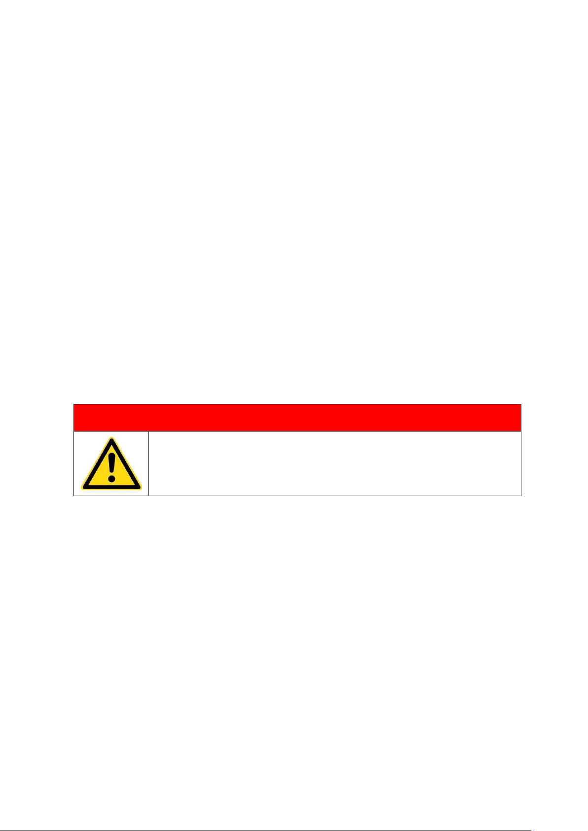
WARNING
People with pacemaker should not be allowed to demount or maintain the
magnetically coupled pump!
Any working methods that have a negative effect on the technical safety of the temperature control unit must
not be used. The operator must ensure that the temperature control unit is operated only in flawless condition.
Page 7
[7]
User Guidelines – TCU-90L 12-06-2019 Vers. 003
If necessary, the company using the equipment must obligate the operating personnel to wear protective
clothing.
For all tasks having to do with set-up, start-up, operating, modification of operating conditions and operational
modes, maintenance, inspection and repair, any shutdown procedures stated to be necessary in the
operating instructions must be followed.
2.4.4 Changing the Parameters
The parameters of the control system may only be changed by personnel trained by MOULDPRO.
No parameters in the device configuration may be changed without consulting MOULDPRO.
The relevant accident prevention regulations and the generally accepted principles of safety engineering,
occupational medicine and structural engineering must be observed. The national safety regulations must
also be obeyed.
2.4.5 Residual risks
Any unauthorized modifications and changes to the temperature control unit as well as unauthorized changes
to the parameters of the control system are prohibited for reasons of safety.
If the temperature control unit is damaged, it must not remain in use; the defective part must be replaced or
repaired immediately. Only original MOULDPRO replacement parts may be used. Damage due to use of third
party parts voids any and all warranty claims.
DANGER
The temperature control unit must be rendered currentless before it is opened!
Press the main switch on the temperature control unit and unplug mains plug!
Danger due to electrical shock!
Repair leaks in the temperature control circuit (device, connecting lines, etc.) immediately.
In temperature control units that use oil as a heat transfer medium, it should be noted that oil is flammable
under certain conditions. For this reason, the temperature control unit must not be located in the vicinity of
heat sources. The thermal insulation in the device must always be kept clean. Insulation that is soaked with
thermal oil poses an increased risk of fire.
Burning thermal oil can be extinguished using a spray foam fire extinguisher, a powder fire extinguisher
(avoid with dust-sensitive plants, control systems, EDP, etc.) or a CO2 fire extinguisher. The appropriate fire
extinguisher must be provided by the operator, taking into account the equipment located in the room and the
mandatory safety regulations.
The temperature control unit may only be operated when all safety systems are completely installed and
intact. The temperature control unit must be protected against sprays and cleaning agents.
Page 8
[8]
User Guidelines – TCU-90L 12-06-2019 Vers. 003
Before detaching connecting lines in the temperature control circuit and depending on the outlet temperature,
allow the temperature control unit to cool down first and then turn it off. Check that the pump is no longer
running.
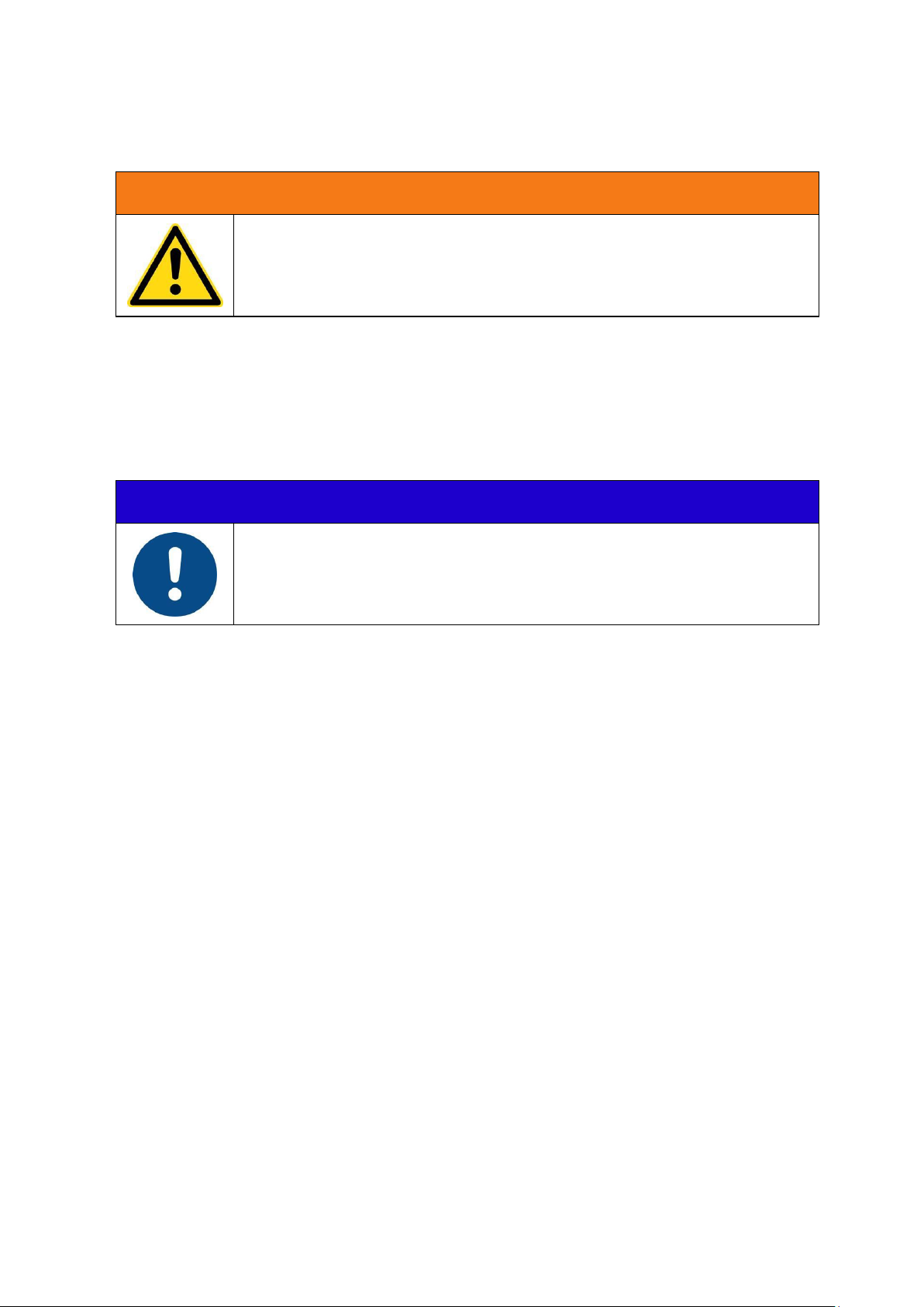
WARNING
Important - danger of injury in the event of escaping water or oil!
2.5 Using this Documentation
This documentation contains important information for safe, economical operation and for proper
maintenance of the device.
Compliance with this documentation helps to avoid danger, minimize repair costs and downtime, and
increase the dependability and service life of the unit/system.
NOTE
The operating instructions should be kept near the corresponding unit and
always be accessible to operating and maintenance personnel.
2.5.1 Additional Documentation
The included documentation is completely correct for the basic versions of units. Components that do not
belong to the basic hardware are noted as extra equipment. The corresponding additional documents are
included with special versions of devices. Any additional documents supplement and/or replace the
descriptions contained in this documentation, which are then either invalid or only conditionally valid.
Page 9
[9]
User Guidelines – TCU-90L 12-06-2019 Vers. 003
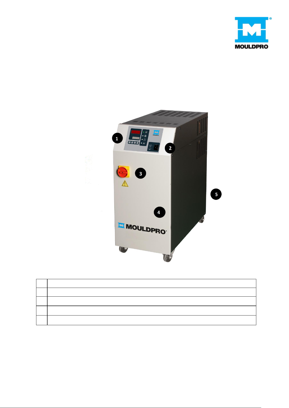
3 Overview temperature control unit
3.1 Front view
1
Temperature Controller
2
Pump ON/OFF (TCU-90 and TCU-90L pump direction)
3
Main switch
4
Cover- Electric section
5
Cover– Hydraulic section
Page 10

[10]
User Guidelines – TCU-90L 12-06-2019 Vers. 003
3.2 Rear view
Page 11
[11]
User Guidelines – TCU-90L 12-06-2019 Vers. 003
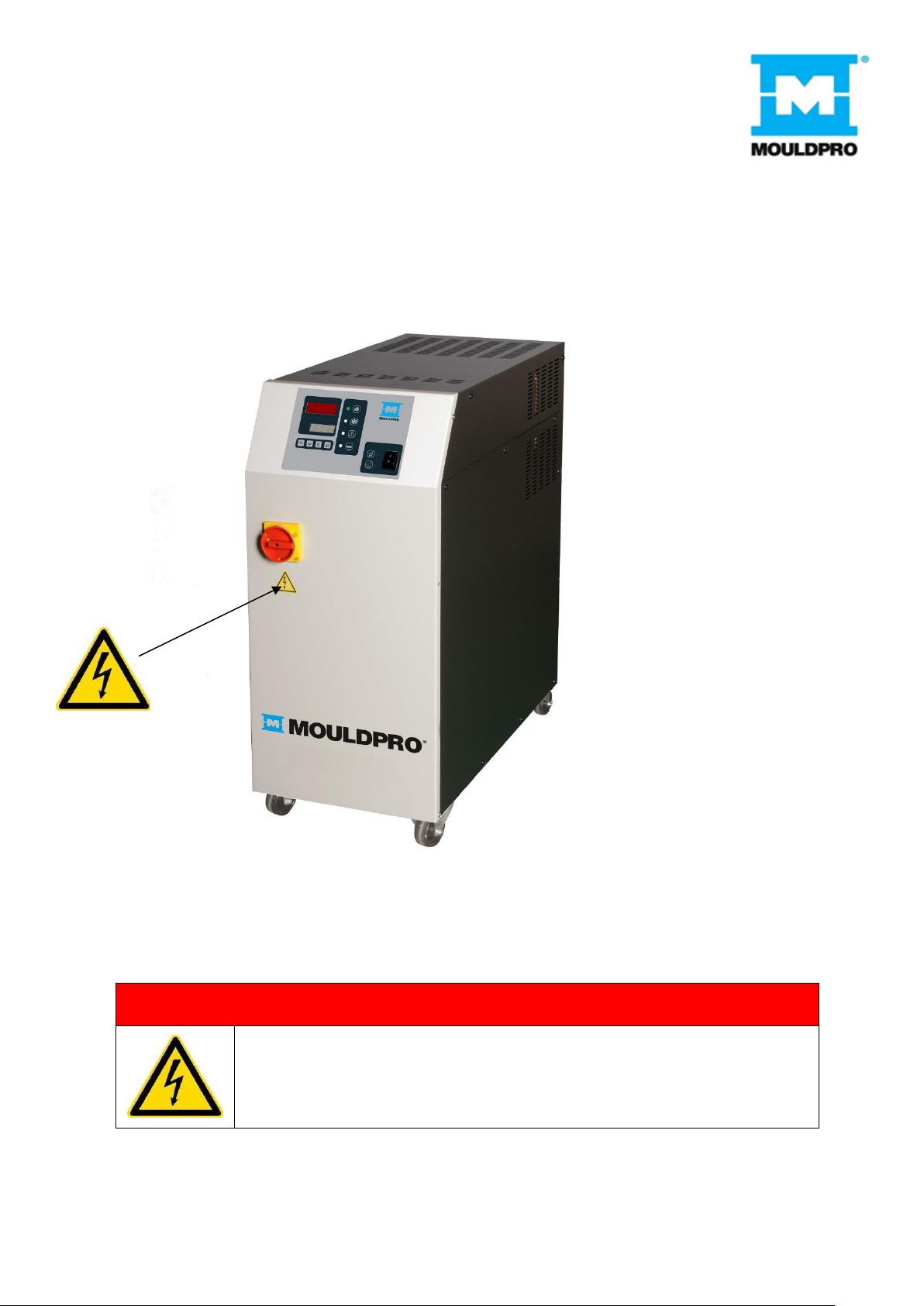
3.3 Identification of residual risk on the unit
On the temperature control unit following pictograms are mounted to identify the residual risk.
DANGER
The temperature control unit must be rendered current less before it is opened!
Turn off the main switch on the temperature control unit and disconnect the
power cord from the wall socket!
Danger due to electrical shock!
Page 12
[12]
User Guidelines – TCU-90L 12-06-2019 Vers. 003
4 Technical Specifications
Temperature range
up to 90°C with water
Temperature control
self-optimizing, electronic microprocessor controller
Heating capacity
Water operation: 18 kW,
Pump capacity
motor 0,50 kW
Pressure mode: max. 3,5 bar / max. 60 l/min
Vacuum mode:
vacuum max. 8mH2O
Cooling capacity
approx. 40 kW at 90°C
Filling amount
approx. 35 liters
Connections
to mould
3/4“ BSP female thread
from mould
3/4“ BSP female thread
cooling water inlet with water filter
3/4“ BSP female thread
cooling water outlet
1/2“ BSP male thread
Dimensions (L×W×H)
750 × 365 × 78 5 mm
Weight
approx. 60 kg empty
Category of protection
IP-44
Electric
In separate switch cabinet, easily accessible from the front
Page 13
[13]
User Guidelines – TCU-90L 12-06-2019 Vers. 003
5 Installation
Before starting the unit, the electrical and hydraulic connections have to be installed. The installation of the
unit has to be done in the order of the following chapters. After the proper installation, the unit is ready to use.
DANGER
The temperature control unit must only be operated with water. Do not use
solvents or other explosive substances such as petrol, toluene, etc. in the
water.
CAUTION
When starting the unit without the prescribed connections the unit can be
damaged.
Water quality – do not use water with chlorine addition.
NOTE
Observe the General Safety Information!
Before installing corresponding chapter of the manual should be read!
5.1 Installing and dimensions of the temperature control unit
The temperature control unit is designed for an ambient temperature of +10 up to 40°C. Sufficient ventilation
must be ensured during set-up. The distance between the temperature control unit and other facilities must
be at least 10cm. The ventilation opening must be free.
Check the unit of completeness and possible damages.
The unit has to be installed in a suitable location on even ground. It must be stand up right on the
wheels (castors).
The unit is not protected against splash water and is not suitable for use in hazardous location. The
unit must not be used in the open air.
The unit must not be transported lying down, transport in any other position than up right, will damage
the unit.
Page 14

[14]
User Guidelines – TCU-90L 12-06-2019 Vers. 003
WARNING
The temperature control unit can release excess pressure. Danger of injury in
the event of escaping steam!
Never start up the unit without the protection cover! Never use the unit in
hazardous location!
Repair leaks immediately! Observe local laws during set-up!
CAUTION
The temperature control unit may be pressurized!
Only when the pressure gauge shows 0 bar, disconnect hoses!
5.2 Connections
Before installing, the connecting lines between temperature control unit and consumer must be subjected
following inspections:
Verify that channels on the consumers are unobstructed
Remove fouling, e.g. remove shaving in the lines
Rust and lime deposits must be removed because the greatly interfere with the heat exchange between
consumer and heat transfer medium and increase the pressure drop in the consumer.
For the connecting lines (to and from mould, cooling water inlet and outlet, etc.) the following internal
diameters of hoses are recommended:
Thread on the unit
Internal hose-Ø
3/8“
10 mm
1/2“
15 mm
3/4“
20 mm
1“
25 mm
DN32
32 mm
Page 15

[15]
User Guidelines – TCU-90L 12-06-2019 Vers. 003
Quick release couplings will give reduced flow. If the recommended tube size cannot be connected to the
mould, the connection at the mould should be reduced and not the connection on the temperature control
unit. In that way pressure, drops can be avoided.
For the cooling water connections it’s enough to use pressure- and temperature-resistant rubber hoses. The
tap water pressure has to be between 2,0 and 5,0 bar. We recommend to conduct the water from the unit
(cooling water outlet) to an unpressurized outlet.
WARNING
To ensure the operational safety is essential to use pressure- and temperatureresistant hoses. Pressure-resistant up to 20 bar / temperature-resistant up to
+200°C.
For reason of safety, the cooling must always be connected!
NOTE
Process water filter on the return line reduces contamination in the unit, which
can cause a unit failure (pollution of the solenoid valve).
Mark and take down the maximum temperature for which the connections are
suitable!
5.3 Power supply
Compare supply voltage and frequency with the information on the serial plate. Verify the rating of the
preliminary fuse according to the information in the electrical diagram. Observe local laws during set-up!
Power cable:
Phases
black / brown
L1 / L2 / L3
Earth
yellow/green
PE
Page 16

[16]
User Guidelines – TCU-90L 12-06-2019 Vers. 003
WARNING
The unit may only be connected by a competent electrician.
Ensure easy access to means for cutting the power supply (mains adapter or
mains connection), the access must be positioned in a distance of 0.6 and 1.9m
above the access level.
Do not connect the power supply until the heating medium hoses are
connected!
5.4 Initial operation - Filling
The temperature control unit has to be connected hydraulically and electrically. Possible block valve must be
open.
Switch on the unit electrically: Turn on the main switch and press the unit ON/OFF-switch
After switching on the unit the pump starts and fills the system with water, as well as automatically ventilating
the machine. In the meantime the yellow lamp lights and the horn sound. The unit can stop and start until the
system is completely filled. If only the yellow lamp is lit, the unit is running and no horn sounds, the automatic
refilling is running.
5.5 Pump rotation check
At the rear side of the unit the direction of rotation can be checked. The unit has been connected to the main
supply, hoses must be mounted and heat transfer medium has been filled. Identify the sense of rotation of
the motor by switching it on shortly. The sense of rotation must be clockwise as shown by the arrow.
If the sense of rotation is anti-clockwise invert two phases on the electrical connection. This has to be done
by a qualified electrician.
5.6 Display of pump pressure
The pump pressure is shown on the manometer.
WARNING
The temperature control unit may be pressurised!
Only when the pressure gauge shows 0 bar, disconnect hoses!
6 Operations
The temperature controller controls the unit
The temperature controller is a universal controller for all MOULDPRO units.
Page 17

[17]
User Guidelines – TCU-90L 12-06-2019 Vers. 003
6.1 Overview
1
Display of set value
2
Display of actual value
3
Function keys
4
Led Keys
5
Pump –On/Off / Pump direction (on TCU- 90 and TCU- 90L)
Page 18

[18]
User Guidelines – TCU-90L 12-06-2019 Vers. 003
LEDs process information and start pump.
1
2
3
4
5
6
1. Heating led
2. Cooling led.
3. Overload TCU pump led.
4. Low fluid level led.
5. Pump pressure function.
6. Pump depression function.
7. (5 + 6 Only model TCU-90 and TCU-90L)
Page 19

[19]
User Guidelines – TCU-90L 12-06-2019 Vers. 003
7 Display and Parameter settings
Zone A
Zone B
Page 20

[20]
User Guidelines – TCU-90L 12-06-2019 Vers. 003
To change set point press . Digit on the right side will flash, to change the value press or .
In order to change the digit press .
Press to save changes.
To enter the programming SETS, hold the key and then hold simultaneously the key .
Then in A zone of the display will show ST-0 : To go to the desired ST press
Once in the desired ST, press We visualize the first parameter in the ST.
To change the parameter press , to change the parameter value press the keys
or
to
change the digit press .
To save changes press .
Page 21

[21]
User Guidelines – TCU-90L 12-06-2019 Vers. 003
8 Alarm display
Alarm display
Description
Alarm display
Description
Maximum process start time.
User adjustable. Restart TCU
unit
Thermocouple error.
Disable the heating and pump.
Restarts activation leak monitoring
Minimum return flow alarm. User
adjustable. Disables heating.
Overload pump protection.
Disable heating and pump. Restarts
activation leak monitoring
Connection between flow meter
and PCB card is broken.
Disables heating.
Maximum drive pump. User
adjustable.
Disable heating and pump. Restarts
activation leak monitoring
Connection between process
pressure transducer and PCB
card is broken.
Maximum temperature difference
between process and setpoint
User adjustable
Connection between return
process pressure transducer
and PCB card is broken.
Maximum and minimum temperature
difference between process and
setpoint. User adjustable.
Page 22

[22]
User Guidelines – TCU-90L 12-06-2019 Vers. 003
Connection between Remote
set point signal 4...20mA o
0..10Vdc is broken. Holds last
Set point value
Possible water leaking problem in the
process.
Disable heating and pump. Restarts
TCU unit.
No connection between PCB
card and RS485 o 0..20mA.
Holds last Setpoint value
Low water level for more than 10
seconds continuously in the TCU unit
tank. Disable heating and pump.
Restarts TCU unit.
9 Standard PCB settings.
Depending on TCU model and activated options, pressing the
key will be shown on the display in B area.
Leak monitoring
Pressure pump outlet
Return pressure process
Process flow in return
Return temperature
Return process thermocouple broken
Other messages can be seen in A-B area pressing
if TCU unit has activated configurable relays
(R2 or R3).
Page 23

[23]
User Guidelines – TCU-90L 12-06-2019 Vers. 003
Configured relays
Activated relays
If REMOTE SET POINT function is activated by a signal 4..20mA or
external 0..10Vdc, in B area will show in cycles of 3 seconds
If TCU unit is working through RS485 or 0..20mA
communications in B area will show in cycles of 3 seconds
If we had more machines linked, second TCU unit will show in cycles of 3
seconds
Page 24

[24]
User Guidelines – TCU-90L 12-06-2019 Vers. 003
9.1 Advanced Parameter settings
Each unit requires a different program setting. For each model is a program defined that not every parameter
must be set manually. In this program, the model specific settings are saved.
Depending on the type of PCB card, and incorporated options into the TCU unit, there are parameters that are not
activated
ST-0
Proportional band of the PID control. Self-adjusting.
Integral time of PID control. Self-adjusting.
Derivative time process. Self-adjusting.
Relay type heating. Not modifiable by the user.
SSR- Enables heating through solid state relays.
Cont- Activates the heating through the contactor KM3.
Heating ramp. Do not change without consulting the manufacturer.
This parameter is activated when entering the PID control.
In cycles 10 seconds, if the temperature has not exceeded this value in degrees,
will activate again heating. If on the contrary it has exceeded, heating is not
activated until the next cycle, which will return him to look.
Heating Brake. Do not change without consulting the manufacturer.
Heating gives 100% less the value of "br". When it comes down to this value,
start the PID control.
In pressurized water machines when set point is more than 105 °, PID control
began at 95 °.
Page 25

[25]
User Guidelines – TCU-90L 12-06-2019 Vers. 003
ST-1
Cooling proportional value. Self-adjusting.
Do not change without consulting the manufacturer.
It is no unit of measure (proportional value that multiplies the time the cooling
solenoid valve is connected. This time is given by the PID).
Cooling Brake. Do not change without consulting the manufacturer.
Cooling gives 100% to the working temperature plus "CL.br" value. When it
comes down to this value, start the PID control.
Cooling ramp. Do not change without consulting the manufacturer.
This parameter is activated when entering the PID control.
In cycles of 8 seconds, if the temperature has not exceeded this value, it will
activate again cooling. If on the contrary it has exceeded, cooling is not activated
until the next cycle, which will return him to look.
ST-2
Type of thermocouple. Do not change without consulting the manufacturer.
We choose if the thermocouple is J type (TC 1) or Pt1000 (Pt1).
Flow meter activation.
Activate or not the flowmeter. On-OFF.
Flowmeter signal. Do not change without consulting the manufacturer.
Flow meter signal is done by 4...20mA (SrC.A) or 0..10Vdc (SrC.u).
Activation return sensor.
Activate or not in the display the return / external thermocouple
On-OFF.
Type of return / external thermocouple
We choose if the thermocouple is J type (TC 1) or Pt1000 (Pt1).
Page 26

[26]
User Guidelines – TCU-90L 12-06-2019 Vers. 003
ST-3
Temperature type alarm.
rEL: relative on the set point. Just above value as "SP.AL" parameter.
GAP: on the set point above and below value as "SP.AL" parameter. Activatable
when TCU unit reached the set point.
Overtemperature alarm.
It is the alarm value in degrees will act respect to the set point.
Alarm relay action.
dir: Connector CNM1 activates the signal alarm by NO contact .
rEu: Connector CNM1 activates the signal alarm by NC contact.
Enabling remote set point.
Activate or not the remote set point On-OFF.
Remote set point.
Remote set point signal "SrC.A" 4..20mA or "SrC.u" 0..10Vdc
Full-scale remote set point.
It is the value in degrees of the maximum temperature of the remote set point.
Minimum scale remote set point.
It is the value in degrees of the mínimum temperature of the remote set point.
IMPORTANT: If TCU unit has selected the entry "Sr.SC" as "SrC.u" (input
0..10Vdc) the minimum range may not be the value in degrees 0Vdc.
Maximum value of remote set point.
Maximum value in degrees TCU unit can be set by remote set point.
Outlet process temperature.
Type of Input /Output temperature, is done through mA "out.Â" (4-20 mA) or
volts "Out.u" (0-10 Vdc). These values will always be proportional between the
values in degrees that have been made to the parameters of St-4 "SP.LL" (4
mA-0 Vdc) and "SP.HL" (20 mA-10 Vdc).
Page 27

[27]
User Guidelines – TCU-90L 12-06-2019 Vers. 003
ST-4
Offset temperature correction.
It used to correct the reading of temperature for above and below respect to an
external measurement probe.
Unit temperature.
We choose if we want the temperature in degrees Celsius "° C" or degrees
Fahrenheit "F".
Minimum set point setting.
It is the minimum temperature machine can be set.
Maximum set point setting.
It is the maximum temperature machine can be set.
Relay 1 configuration.
Not configurable by the user.
Value in degrees, bars, liters/minute, depending on the configuration of the
previous parameter "r1".
Not configurable by the user.
Relay 2 configuration
Configurable as:
OFF: Disabled
tP1: Output temperature to the process.
tP2: Return temperature process.
P1: Pump pressure.
P2: Return process pressure.
FM1: Return process flow.
AL: General alarm.
Value in degrees, bars, liters/minute, depending on the configuration of the
previous parameter "r2".
Relay 3 configuration
Configurable as:
OFF: Disabled
tP1: Output temperature to the process.
tP2: Return temperature process.
P1: Pump pressure.
P2: Return process pressure.
FM1: Return process flow.
AL: General alarm.
Value in degrees, bars, liters/minute, depending on the configuration of the
previous parameter "r3".
Page 28

[28]
User Guidelines – TCU-90L 12-06-2019 Vers. 003
ST-5
By entering the value 1562, let us enter the St-0 and St-1.
Software version.
ST-6
Value to 0, the time to enter the programming SETS is 5 seconds.
With value 1, the time to enter the programming SETS is 15 seconds.
ST-7
Enabling communications.
Activate or communications On-OFF.
Address assigned to the TCU unit.
The first TCU unit will be address 1, if more linked machines the following would
be address 2 and so on.
Transmission speed.
"0" (2400bauds), "1" (4800 baud) and "2" (9600 baud).
Parity bit.
"0" (no parity), "1" (non parity) i "2" (even parity).
Page 29

[29]
User Guidelines – TCU-90L 12-06-2019 Vers. 003
Interface type. "420" (4-20mA) or "485" (RS485).
When you select "485", the following parameter dEn not appear.
Data enable.
When the interface type is 420 and only have one TCU linked to the MASTER
machine, dEn parameter value is "1" (close circuit); if more than one TCU linked
all will have dEn value "0" less the last one it will have dEn value “1”.
ST-8
Fluid level setting.
Not modifiable by the user.
Select if the level control is done by electrode "ELEC" or buoy "BuOY".
Extra time level detection.
Water filling valve retard disconnection time. Value in seconds.
NO CHANGE WITHOUT CONSULT THE MANUFACTURER
Extra time no level detection.
Water filling valve retard connection time. Value in seconds.
NO CHANGE WITHOUT CONSULT THE MANUFACTURER
Display activation drive pump.
Activate or not the on-off display.
Alarm output drive pump.
Value in bars.
Initial scale transducer drive pump.
Value in bars.
NO CHANGE WITHOUT CONSULT THE MANUFACTURER
Full-scale transducer drive pump.
Value in bars.
NO CHANGE WITHOUT CONSULT THE MANUFACTURER
Display Activation return pressure.
Activate or not the display. On-off
Initial scale return transducer drive pump.
Value in bars.
NO CHANGE WITHOUT CONSULT THE MANUFACTURER
Page 30

[30]
User Guidelines – TCU-90L 12-06-2019 Vers. 003
Full scale return transducer drive pump.
Value in bars.
NO CHANGE WITHOUT CONSULT THE MANUFACTURER
Maximum process start time.
Value in minutes.
NO CHANGE WITHOUT CONSULT THE MANUFACTURER
Contact NO or NC input level.
Not modifiable by the user.
Leak monitoring.
Activate or not the monitoring control. On-OFF.
10 Leak monitoring
Default leak monitoring is enabled, and can be disabled by LM parameter in the St-8 menu.
The process works as follows: Water / oil TCU units:
When process start, letter L (zone B) will flash. When the TCU pump is more than 2 minutes running in continuous, (this
will mean that there is no demand for water/oil in the process), the letter L will stop flashing.
From this moment, leak monitoring is enabled. Leak detection:
Once monitoring is enabled (in water process) if we demand for water more than once in an hour, or repetitive demands
on for 4 consecutive hours, in zone A message is displayed
Will activate the audible alarm by turning off the pump and heating temperature control unit.
Once the user has disconnected the pump switch and confirmed the alarm by pressing
Page 31

[31]
User Guidelines – TCU-90L 12-06-2019 Vers. 003
Fix the leakage problem, fixed the leakage connect again the pump switch TCU unit will restart automatically.
Another leak detection (designed for oil TCU units) is:
If the process is more than 10 seconds in oil demand (this may be due to a loss level in the TCU unit)
because filling is manual and not incorporating automatic filling in area A the message displayed will be
Will activate the audible alarm by turning off the pump and heating temperature control unit.
Once the user has disconnected the pump switch and confirmed the alarm by pressing
Fix the leakage problem, fixed the leakage connect again the pump switch TCU unit will restart automatically.
10.1 Deactivate Leak monitoring
If the user disables leak monitoring, the letter L (zone B) will not appear.
The alarm will be
disabled.
Alarm can act, whether the process is water or oil but, pump must be running in continues for 2
minutes.
Page 32

[32]
User Guidelines – TCU-90L 12-06-2019 Vers. 003
11 Configurable relays
Depending on TCU model, can add up to 2 configurable relays for user process automation. Making the TCU
unit in a process control system.
These switched relays with potential free contacts (support up to 6A), listed as r2 and r3 in the St-4 menu,
can be configured to work with the control signals incorporating the TCU unit (which are activated by
exceeding the value programmed), are:
Pump pressure.
Return pressure.
Outlet process temperature.
Inlet process temperature.
Flow lit/min in return process.
General alarm.
Examples:
The user needs to know when the mold temperature has reached the value he wants to start the process.
Through external thermocouple located in the mold provided by the user to the TCU unit, will control the
temperature using the r3 relay.
When the temperature exceeds the set value, the relay r3 provide the user a signal it allow to start the
application.
If the mold have no thermocouple could be done as follows:
We will control the temperature of the return process by
the thermocouple at the temperature control unit with relay r3.
Check externally (contact thermocouple, laser gun) when the mold is at optimum operating temperature, and
display on the screen which is the return temperature at that time. In this way we could set the value in the
relay r3, which will provide the user for future occasions, the signal to start its application in this mold.
Page 33

[33]
User Guidelines – TCU-90L 12-06-2019 Vers. 003
Prevent overpressure in inlet mold.
This application could be interesting when our mold has parts that cannot withstand high pressures and need
early detection to prevent possible damage.
We will control the pump discharge pressure to the entrance of the user process by r2 with a value (example
3 bar). If this pressure is higher than the preset in r2, this will provide signal to the user, which could perform
a bypass between inlet and outlet of the mold and an alarm.
Page 34

[34]
User Guidelines – TCU-90L 12-06-2019 Vers. 003
12 Description PCB card connectors
13 Maintenance
Inspection and maintenance have to be done by instructed staff (competent).
Page 35

[35]
User Guidelines – TCU-90L 12-06-2019 Vers. 003
The following maintenance intervals may be required subject to use and environment:
Water filter
clean / replace
every month
Pump motor
blow out the fan
every 6 months
Hoses and pipes
check tightness
every 6 months
Pump
check tightness
every 6 months
Bolts and seals
check tightness
every 12 months
Heat transfer oil (only valid for oil units)
change
every 4‘000 working hours
For extreme service, the intervals must be shortened accordingly. For temperature control units running with
oil, the oil should be changed yearly, depending on the temperature. Comply with the directives and
recommendations of the oil manufacturer!
13.1 Inspection
Before starting the unit has to be checked the general condition of the temperature control unit, the electrical
connection and the tightness of the connections and hoses (including the consumer).
13.2 Cleaning
The temperature control unit has to be checked and cleaned periodically. Before maintenance the unit has to
be disconnected from the power supply.
13.3 Repair
Established defects must be repaired. To guarantee safety the unit must be repaired with original
MOULDPRO spare parts only.
Page 36

[36]
User Guidelines – TCU-90L 12-06-2019 Vers. 003
WARNING
The temperature control unit must be current less before opening!
Press the main switch on the temperature control unit and pull out the mains plug!
There is a danger of electric shock!
Caution – risk of injury from leaking hot water or oil!
CAUTION
Waste oil has to be disposed as prescribed by law. Never let waste oil come into the
sewage system or soil.
14 Out-of-service / transport
Cool the temperature control unit down, mould drainage, turn it off, press the main switch and disconnect the
power supply. Disconnect all hoses from the temperature control unit.
The temperature control unit is to be emptied before shipping. The danger of freezing (bursting of pipes or
other components) at low temperatures can be reduced. The unit must be transported and/or stored in the
operating position.
CAUTION
Drain the unit to avoid freezing damages!
Avoid compressed air, blowing out with compressed air can damage the unit!
Never transport the unit lying – Lying transport will destroy the unit!
15 Disposal
The temperature control unit must be drained completely and disposed of in accordance with local
regulations.
The temperature control unit can also be returned to MOULDPRO for disposal.
Page 37

[37]
User Guidelines – TCU-90L 12-06-2019 Vers. 003
16 Water quality
Depending on the unit to be cooled or heat-balanced, certain requirements have to be met by the cooling water regarding
its quality. In order to protect all parts of the unit against corrosion, Mouldpro recommends as a matter of principle to treat
the water with a suitable cleaning agent (anticorrosive as well as non-ferrous metal protector and hardness stabilizer). In
addition, depending on the materials installed, the temperatures and the type of process, the following water quality data
have to be met.
As a rule the following data apply:
HYDROLOGICAL DATA
MAX
UNIT
PH-value
7,5 – 8,5
-
Conductivity
< 150
mS/m
Total hardness
< 15
°dH
Carbonate hardness
< 4
°dH
Carbonate hardness in case of
stabilization of hardness
< 20
°dH
Chlorid Cl
<100
mg/l
Sulphate-So4
< 150
mg/l
Ammonium NH4
< 1
mg/l
Iron Fe
< 0,2
mg/l
Manganese
< 0,1
mg/l
free from solids
Furthermore the following applies:
Systems with stainless steel
Systems with aluminium
PH-value
min. 7,0 max. 8,0
Temperatures below 5°C
o When employing chillers at temperatures below + 5°C, an anti-freeze medium with corrosion inhibitor
must be added.
Temperatures over 120°C
o At water temperatures over 120°C glycol may not be used.
If the recommended water qualities are not met, the components of the unit will be damaged due to corrosion. Mouldpro
will not accept any liability for any such damages
Chlorid Cl
Temp. < 50 °C
max. 100
mg/l
Chlorid Cl
Temp. 50 up to 90 °C
max. 50
mg/l
Chlorid Cl
Temp. > 90 °C
max. 30
mg/l
Page 38

[38]
User Guidelines – TCU-90L 12-06-2019 Vers. 003
17 Electrical diagram
Page 39

[39]
User Guidelines – TCU-90L 12-06-2019 Vers. 003
18 Water Circuit Diagram
Page 40

[40]
User Guidelines – TCU-90L 12-06-2019 Vers. 003
19 Control Circuit diagram
Page 41

[41]
User Guidelines – TCU-90L 12-06-2019 Vers. 003
20 Components and spare part list
Page 42

[42]
User Guidelines – TCU-90L 12-06-2019 Vers. 003
Page 43

[43]
User Guidelines – TCU-90L 12-06-2019 Vers. 003
Change log
Date of change
Change
Version
26-04-2019
layout
002
12-06-2019
Spare partslist
003
 Loading...