

Motus M660BU, M660BUL, M660BR, M660BRL Service Manual

M660BU, M660BUL, M660BR, M660BRL
Exercise Bike
SERVICE MANUAL
This service manual is for use by Motus trained service providers only.
If you are not a Motus Trained Servicer, you must not attempt to service any Motus product.
Ver 0.1, Oct., 2007
ⓒ Motus Co., Ltd. All Rights reserved.
Unauthorized Reproduction and Distribution Prohibited By Law

1
Motus Exercise Bikes M660BU, M660BUL, M660BR and M660BRL
Table of Contents
SECTION I TROUBLESHOOTING GUIDE
SECTION II HOW TO REPLACE & REPAIR GUIDE
General
SECTION III HOW TO REPLACE & REPAIR GUIDE,
Electronic PCB
SECTION IV ELECTRONIC PCB, CONNECTOR AND
CABLE OVERVIEW
APPENDIX EXPLODED VIEW

2
Motus Exercise Bikes M660BU, M660BUL, M660BR and M660BRL
SECTION I
TROUBLESHOOTING GUIDE
1.1 System Block Diagram
1.2 Troubleshooting Guide
1.3 Troubleshooting Guide for LCD
3
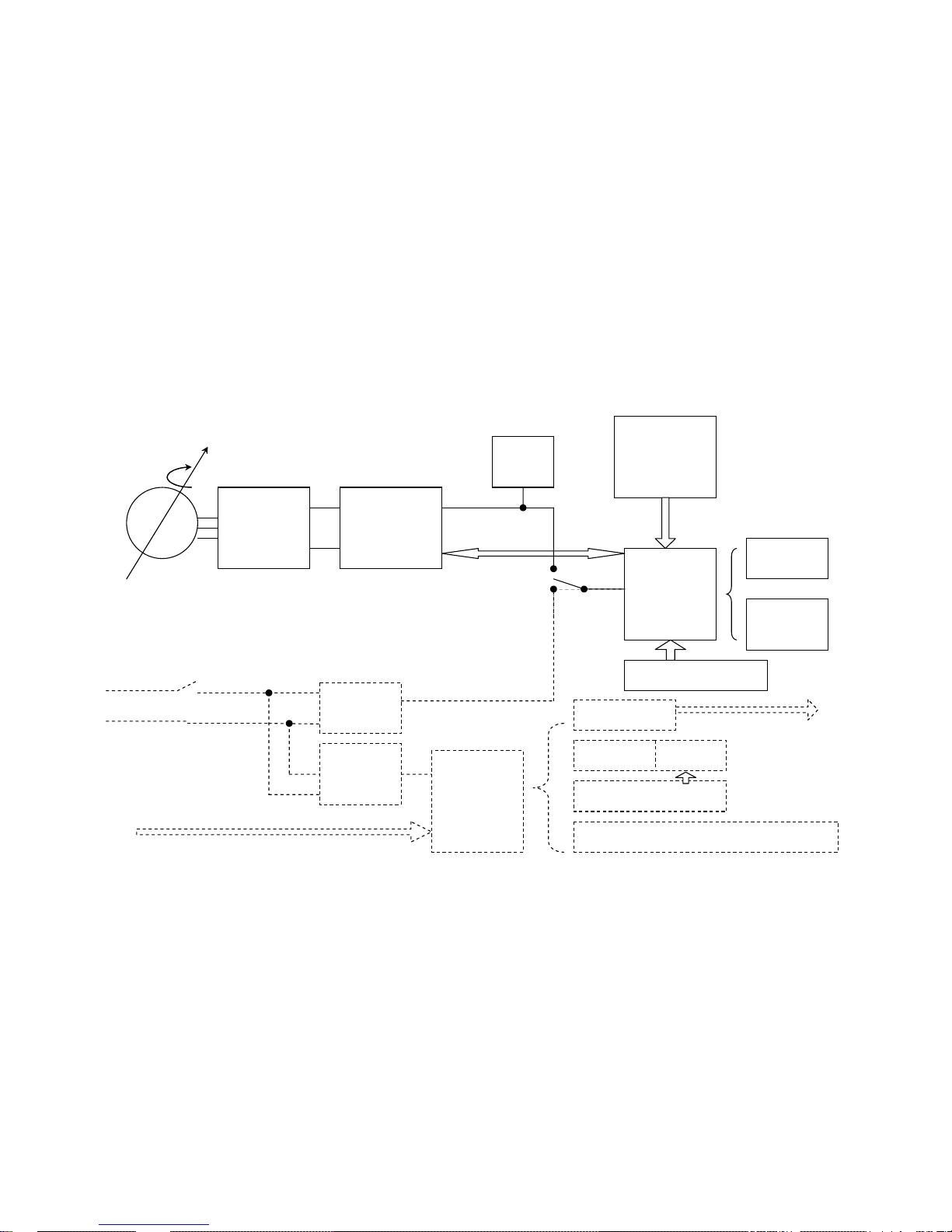
1.1 System Block Diagram
Note: Dotted line is applied to M660BUL/M660BRL
Membrane Overlay Key
Contact HR/
Wireless HR
PCB
MPU PCB
(Main
Processing
Unit)
Operation PCB
(Intensity Up/
Intensity Down/
Start/Enter)
Contact HR
PCB
A/D
PCB
LCD Screen
LCD Lamp Inverter PCB
OSD Button PCB for Channel/Volume/Power-on
Video & Audio Input
(Coaxial, RCA)
Back-Light
Audio Interface
Headphone Jack
SMPS-5V
LCD Power
Adapter
AC
100V/220V
Power ON/OFF
Switch
Switching Mode
Power Supply &
Brake Control
3-Phase
Rectifier with
DC Filter
Gener-
ator
Battery
4
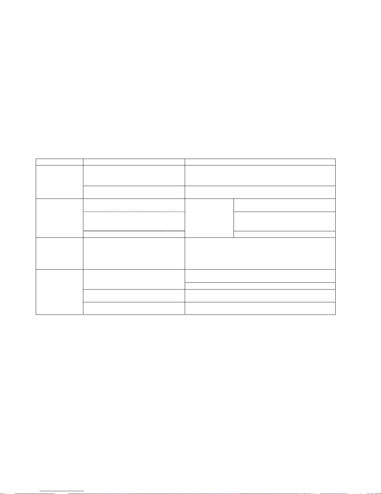
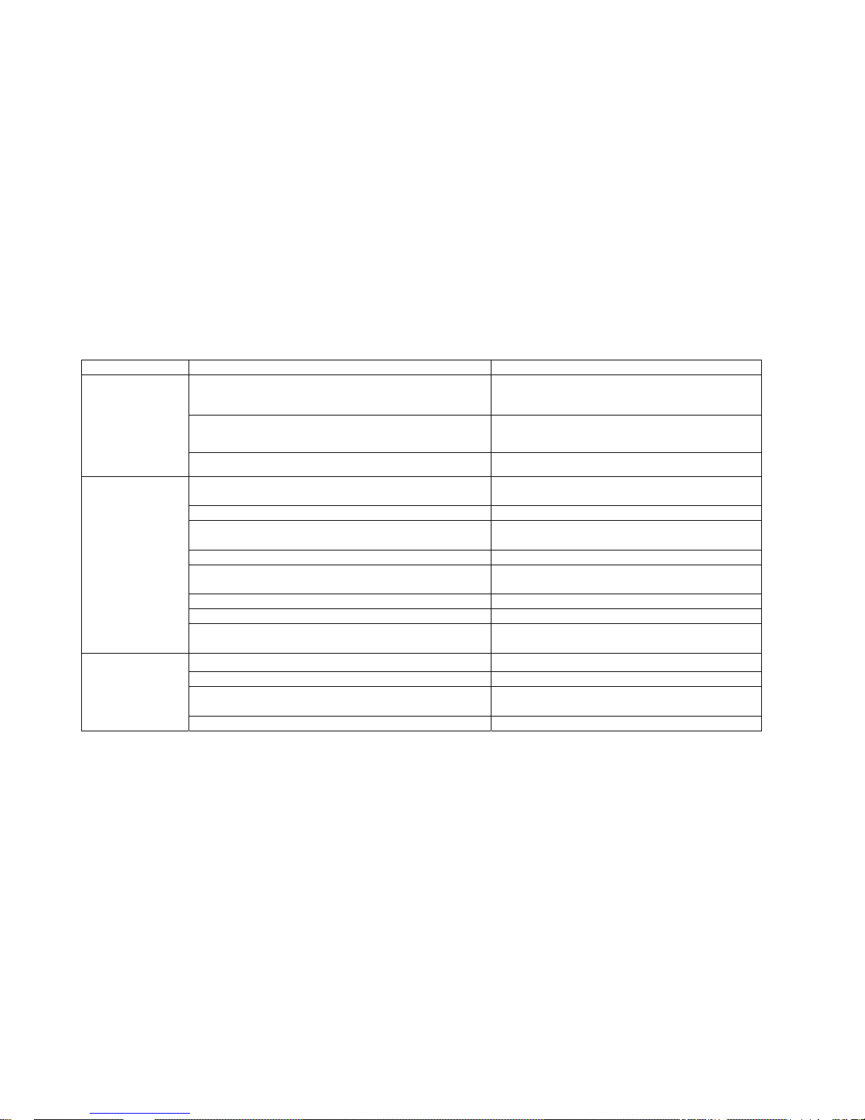
1.2 Troubleshooting Guide
SYMPTOM PROBABLE CAUSE CORRECTIVE ACTION
Line voltage is not present at equipment.
Check the main circuit breaker and wall outlet voltage at the Facility.
If wall outlet voltage is present, then replace line cord.
No power to
Console
(On M660BUL/BRL)
Power-on Switch is damaged.
Replace Power-on Switch if the output voltage of Power Switch is not
present.
Defective SMPS-5V (MPU Power Supply)
If no voltage, replace Defective SMPS-5V (MPU
Power Supply).
Defective Wire Harness
If no voltage, verify that CBB3 interconnected
with CBB4 cable is plugged into both MPU
Board and SMPS-5V. Replace if necessary.
LCD TV is normal,
but Dot-LED and
Numeric LED do not
light up
(On M660BUL/BRL)
Defective MPU Board
Measure the voltage
between pin 1 and
pin 4 on CN2.
If no voltage, replace MPU PCB.
Dot-LED and
Numeric LED are
normal, but LCD TV
does not light up or
is blank
Refer to 1.3 Troubleshooting Guide for LCD. Refer to 1.3 Troubleshooting Guide for LCD.
Using a Multi-meter, verify more than 6VDC at pin-7 and pin-8 on CN1.
If voltage is present, replace MPU board. If not, replace Drive board.
Faulty MPU board or Drive board
Test with substitute MPU board or Drive board. Replace if necessary.
Cable connection or loose wire connection
Verify that main cable CN1 is securely plugged into both MPU board and
Drive board. Replace if necessary.
Console LEDs are
not illuminating
(On M660BU/BR)
Worn or damaged wire harness Inspect wire harness. Replace worn or damaged harness.
5
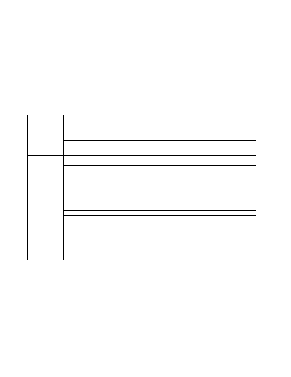
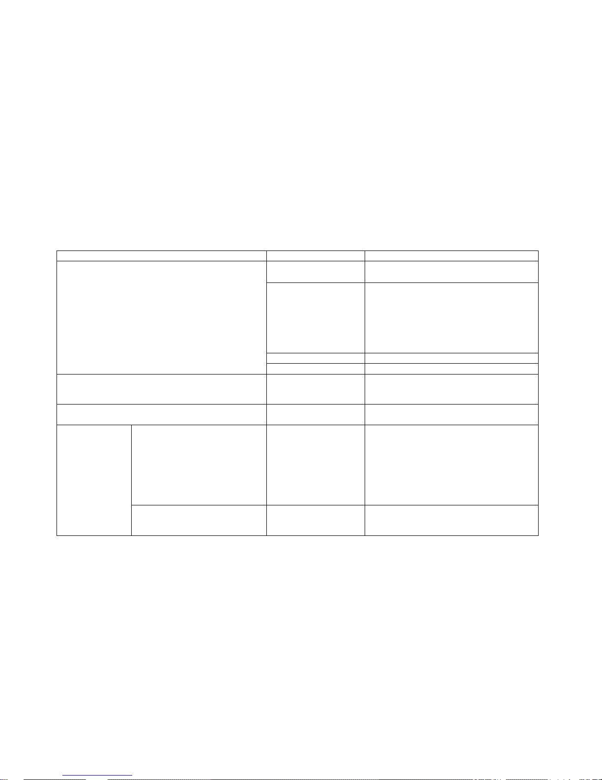
SYMPTOM PROBABLE CAUSE CORRECTIVE ACTION
Faulty Battery, Note: Battery is used only for
M660BU/BR, self-powered model.
Verify that Battery voltage is greater than 6 volts DC. Replace Battery if
the voltage is lower than 6 volts DC.
Test with substitute MPU board. Replace if necessary.
Faulty MPU board or Drive board
Test with substitute Drive board. Replace if necessary.
Cable connection or loose wire connection
Verify that main cable CN1 is plugged into both MPU board and Drive
board. Replace if necessary.
Dot-LED or Numeric
LED lights up and
then fails.
(On M660BU/BR)
Worn or damaged wire harness Inspect wire harness. Replace worn or damaged harness.
Faulty Battery
Verify that Battery voltage is greater than 6 volts DC. Replace Battery if
the voltage is lower than 6 volts DC.
Cable connection
Verify that the cable connection at MPU board and Drive board or the
connection between cables at midpoint is plugged in properly. Using a
Multi-meter, verify continuity on all cables. Replace any defective cables.
Unit does not Auto
Start
(On M660BU/BR)
Faulty Drive board If cable connection is verified as good, replace the Drive board.
Unit does not display
SPEED on Console
Cable connection
Verify that the cable connection at MPU board and Drive board or the
connection between cables at midpoint is plugged in properly. Using a
Multi-meter, verify continuity on all cables. Replace any defective cables.
Pedaling is too slow. Pedal faster.
Program intensity doesn’t challenge user ability. Select higher workout intensity.
Drive Belt is excessively loose Inspect Belt tension. Adjust if necessary.
Cable connection or loose wire connection
Verify that the cable connection at MPU board and Drive board or the
connection between cables at midpoint is securely plugged in properly.
Using a Multi-meter, verify continuity on all cables. Replace any
defective cables.
Worn or damaged wire harness Inspect wire harness. Replace worn or damaged harness.
Faulty Button Switch or Operation Button board
Verify that workout intensity on Console is increased or decreased by
pressing UP/DOWN button switch. Replace Button Switch or Operation
Button board if there is no change on intensity profile.
During exercise
program, pedaling is
insufficiently easy
without providing
adequate resistance.
Defective MPU board or Defective Drive board Test with substitute MPU board or Drive board. Replace if necessary.
6
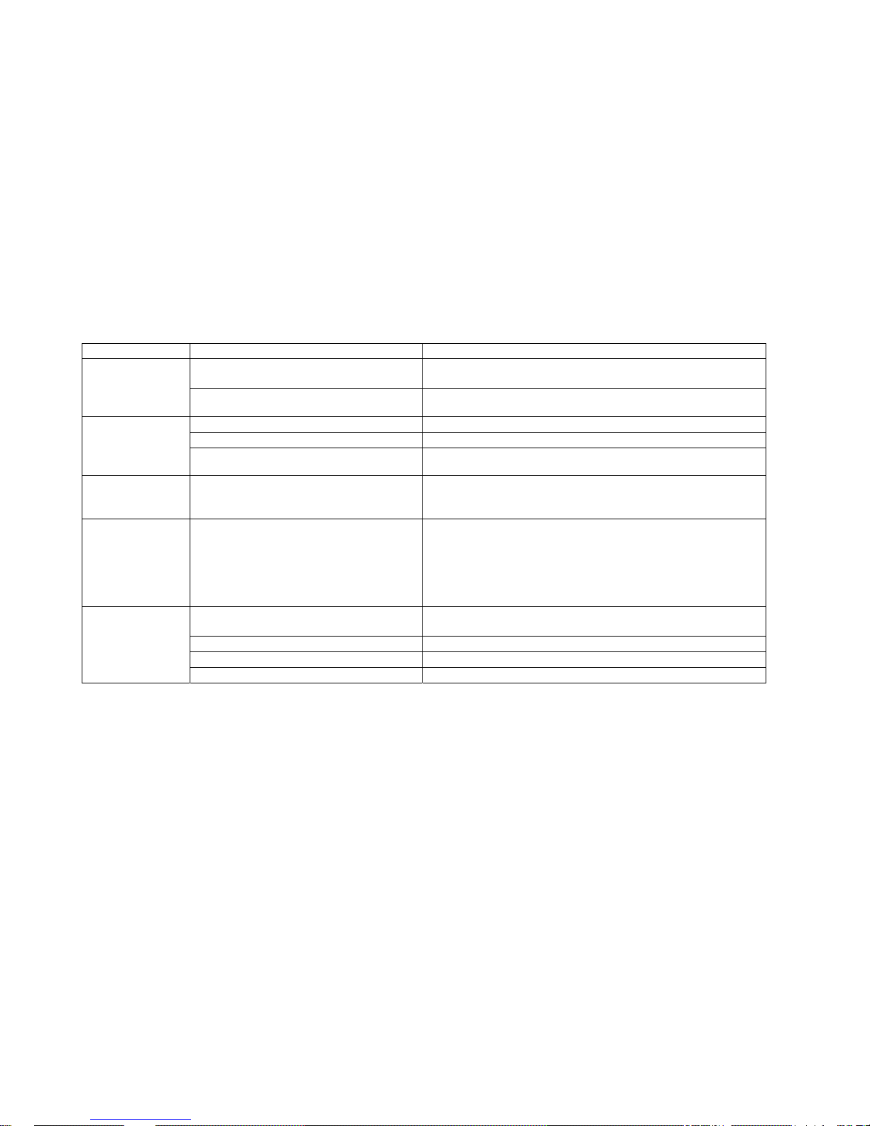
SYMPTOM PROBABLE CAUSE CORRECTIVE ACTION
Malfunction Overlay, Button Switch or Operation
Button board
Replace Overlay, Button Switch or Operation Button board. Display Console
Keys do not function
and Bike does not
respond.
Defective MPU board Test with substitute MPU board. Replace if necessary.
Defective MPU board Test with substitute MPU board. Replace if necessary.
Defective Drive board Test with substitute Drive board. Replace if necessary.
During MANUAL
program, excessive
resistance loading
occurs.
Worn or damaged wire harness Inspect wire harness. Replace worn or damaged harness.
During MANUAL
program, resistance
variance occurs
Pedaling is too slow Pedal faster.
Pedaling is difficult
with restricted
feeling or is not
possible when Bike
has not been started
(no STARY key)
Drive Belt is jammed. Inspect by opening the body covers. Replace if necessary.
Loose hardware
Verify that all hardware has been tightened. Apply Loctite where
necessary.
Drive Belt is worn Replace Belt.
Drive Belt is too loose Inspect Belt. Replace Belt if necessary.
During exercise
program, loud noise
issuing from Bike
Drive Belt is off track, touching other parts Inspect Belt. Relocate if necessary.
7
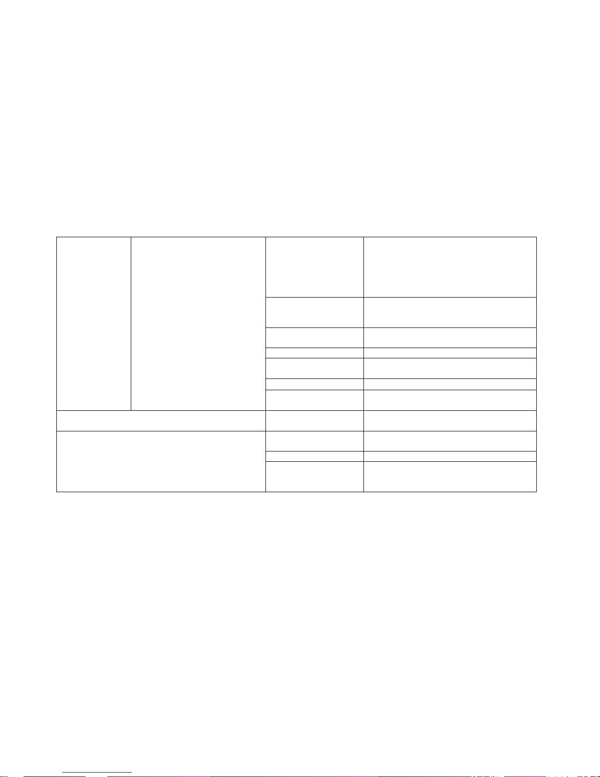
SYMPTOM PROBABLE CAUSE CORRECTIVE ACTION
Electromagnetic interference from television sets, cell phones,
refrigerator, or motor driven exercise equipment.
Keep the treadmill away from the probable cause until
the heart rate readings are accurate.
RF energy source from another chest straps.
Keep another chest strap away more than 1 meter until
the heart rate readings are accurate.
Heart rate reading is
abnormally high or is
displayed even when
Chest Strap or
Contact Heart Rate
sensors are not in
use.
Contact Heart Rate cables are pinched at handle bars. Replace damaged cables.
Chest strap electrodes are not wet enough to sense accurate
heart rate.
Dampen the Chest strap electrodes with tap waters.
The distance between cardio equipments are too close. Maintain the distance more than 30 cm.
Chest strap electrodes are out of monitoring range.
Make sure the chest strap is within 60cm from Wireless
HR PCB.
Chest strap battery is discharged. Replace chest strap or the battery.
Chest strap electrodes are not laid flat or horizontally across
your skin.
Make sure the chest strap electrodes lies flat and
horizontally across your skin.
Faulty chest strap. Replace chest strap.
Faulty Wireless HR PCB. Replace Wireless HR PCB.
Heart rate reading
using wireless chest
strap is erratic or not
displayed
Defective cable or bad connection between Wireless HR PCB
and MPU PCB.
Check the cable and connection is no problem.
Faulty CHR PCB. Replace CHR PCB
Dirty handlebar sensors. Wipe stainless steel sensors with a clean soft cloth.
Defective cable or bad connection between CHR PCB and MPU
PCB.
Check the cable and connection is no problem
Contact Heart Rate
reading is erratic or
not displayed.
User may have an unusual heart rate condition. Let different user grasp sensors to detect any variances.
8
1.3 Troubleshooting Guide for LCD
Symptom/Condition PROBABLE CAUSE CORRECTIVE ACTION
Air/cable setting is not
correct
Follow the set up procedures in LCD manual.
TV signal source is not
supplied.
- Check if the TV signal source is correctly supplied
to A/D PCB from external source.
- Make sure the cable is properly secure.
- If external TV signal is correct, try to connect the
coaxial cable directly to the internal connector in AD
PCB of Console to check whether the internal
cables are wrong or not.
75 ohm coaxial cable is bad. Replace 75 ohm coaxial cable.
Snow and noise are scattering on LCD screen. Any picture is
not found even though channel-up button or channel-down
button is pressed.
A/D Board is damaged. Replace A/D Board with new one.
LCD screen is uniformly white
Internal cable connection is
loose or disconnected.
Check if the connection between LCD screen and
A/D Board is tight. In other word, LVDS cable shown
in picture.
Vertical large white-stripe or Vertical stripe block on LCD
screen
Problem with LCD screen Replace LCD screen
When LCD power is turned on by
pressing TV on/off, “VIDEO”, “S-VIDEO”
or “ANALOG” appears temporarily and
then disappears on the left upper corner
of LCD screen.
TV mode is not set-up.
1) Whenever you press Volume down button, words
are displayed in following order on the left upper
corner of LCD screen.
“ANALOG”=>”VIDEO”=>”S-VIDEO”=>”TV”
2) Press the button until “TV” is displayed.
3) As soon as “TV” is displayed, snow and noise will
be scattering on LCD screen or any picture will be
captured.
LCD screen is dark
or black.
When LCD power is turned on by
pressing TV on/off, “VIDEO”, “S-VIDEO”
or “ANALOG” is NOT displayed on the
LCD Power Supply has a
problem. Power Supply is
used for supplying 12 VDC
Check if LCD Power supply is normally operated or
LED lamp on Power supply body is turned on.
If LED is off,
9
to LCD Overlay Bezel
Assembly.
z replace Power Adapter.
If LED is on,
z tighten midpoint (LCD Power Supply side)
& endpoint (A/D Board side) connection.
z or make sure the voltage of end point is
DC 12 volt.
The cable related to LCD
Lamp Inverter is loose in
either side.
Check if the connection is secure.
TV on/off button is wrong or
stuck.
Replace OSD Button Board.
A/D Board is damaged. Replace A/D Board.
LCD Lamp inverter is
damaged.
Replace LCD Lamp inverter.
LCD Back Light is damaged. Replace LCD screen.
left upper corner of LCD screen.
The connector or cable is
bad.
Replace the connector or cable
Channels or Volume does not change
Button to change channels
or volume does not work.
Replace the button, OSD Button Board or harness
related to it.
Air/cable setting is not
correct
Follow the set up procedures in LCD manual.
Faulty headphones Replace headphones
No sound
Faulty headphone jack
assembly or Audio Interface
Board.
Replace Audio Interface Board or headphone jack.

10
Motus Exercise Bikes M660BU, M660BUL, M660BR and M660BRL
SECTION II
HOW TO REPLACE & REPAIR GUIDE
General
2.1 How to Adjust the Drive Belt (or POLY V-BELT) Tension
2.2 How to Replace the Drive Belt (or POLY V-BELT)
2.3. How to Replace the PEDAL SHAFT
2.4. How to Replace the GENERATOR
2.5. How to Replace the SEAT
2.6. How to Replace the GAS CYLINDER
2.7. How to Replace the PEDAL
2.8. How to Replace the IDLER ASSEMBLY
11
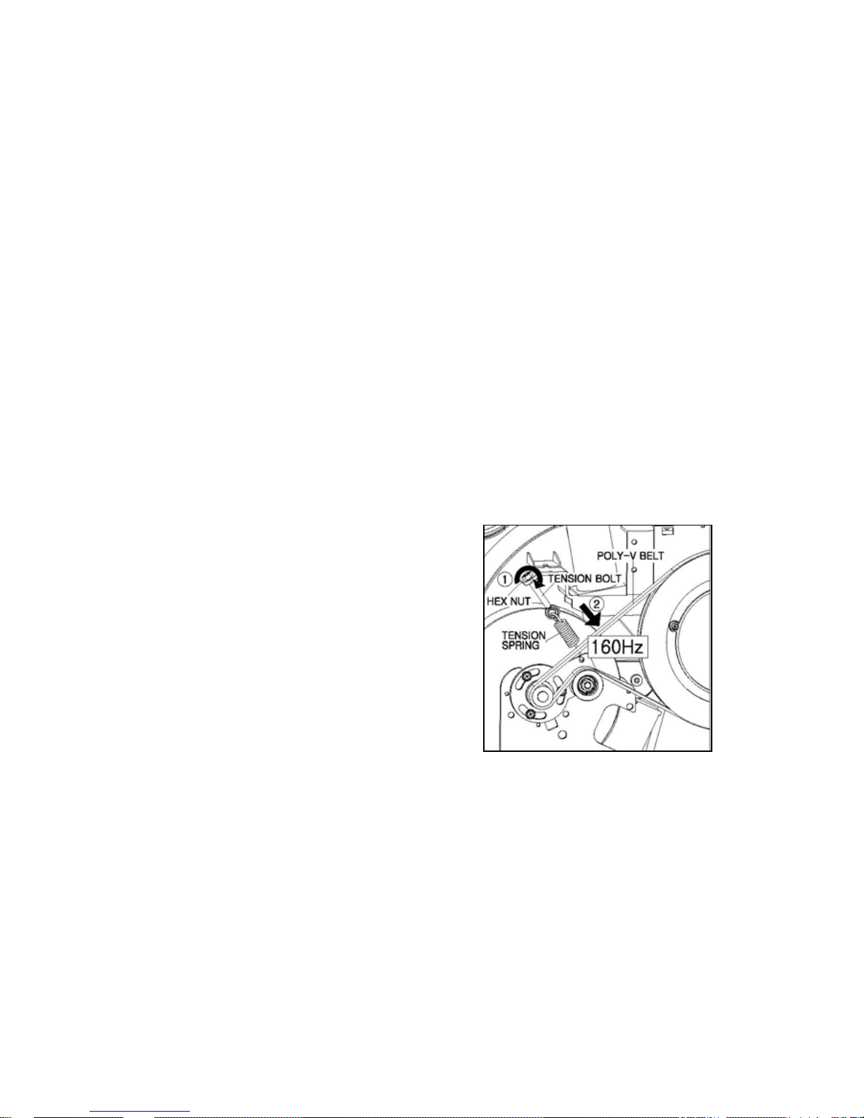
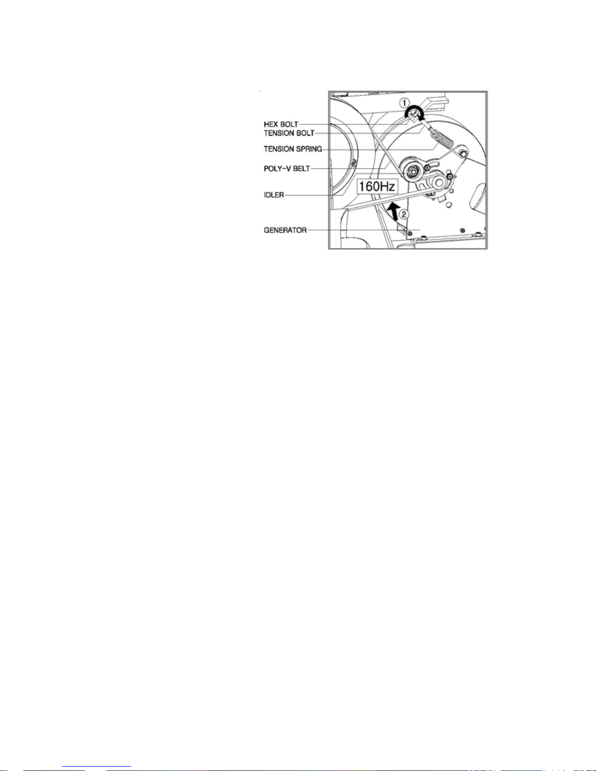
2.1 How to Adjust the Drive Belt (or POLY V-BELT) Tension
The tension of the Drive Belt can be slackened by a long time use and it can cause a slip
between the Drive Belt and Pulleys. The tension is corrected by rotating the TENSION BOLT
connected to the TENSION SPRING.
2.1.1 M660BU/BUL
Do the steps below while referring to the following Exploded Views in Appendix.
C.1 M660BU/BUL_MAIN BODY
1) Turn off the unit power at the switch and then unplug the line cord at wall outlet.
2) Remove the CENTER FOOT_UP (61) by removing two bolts (52) securing the CENTER
FOOT_UP (61) to the Main Body Frame.
3) Remove two bolts (55) securing MAIN BODY CAP (54) to the Main Body Frame.
4) Lift the MAIN BODY CAP (54) and SEAT POST CAP (56) and then fix these to the Gas
Cylinder temporarily by a tape to make it easy to remove the MAIN BODY_R (50).
5) Remove five bolts (51, 52) securing the MAIN
BODY_R (50) to the Main Body Frame and remove
the MAIN BODY_R (50).
6) To increase the belt tension, turn the HEX NUT
(17) clockwise in two or three turns. It makes the
TENSION SPRING (15) tauter.
7) Rotate Pedal in two or three turns and then
measure the tension of the Drive Belt using Tension
Gauge in the position marked in “2”.
8) Repeat 6) thru 8) until the tension reaches 160 Hz.
9) Re-install all of parts in reverse order.
2.1.2 M660BR/BRL
Do the steps below while referring to the following Exploded Views in Appendix.
I.1 M660BR/BRL_MAIN BODY
1) Turn off the unit power at the switch and unplug the line cord at wall outlet.
2) Remove two bolts (52) securing the CENTER FOOT_RE (59) to the Main Body Frame and
Remove the CENTER FOOT_RE (59).
3) Remove two bolts (50) securing the FRONT BODY CAP_FRONT/REAR(58,57) to the Main
12
Body Frame and remove the
FRONT BODY CAP_FRONT/REAR
(58,57).
4) Remove six bolts (46, 56)
fastening the FRONT BODY_R (54)
to the Body Frame and remove the
FRONT BODY_R (54) from the
Body Frame.
5) To increase the belt tension, turn
the HEX NUT (14) clockwise in two
or three turns. It makes the TENSION SPRING (12) tauter
.
Turning the HEX NUT (14) counter clockwise decreases the belt tension.
6) Rotate Pedal in two or three turns and then measure the tension of the Drive Belt using
Tension Gauge in the position marked in “2.”
7) Repeat 5) thru 7) until the tension reaches 160 Hz.
8) Re-install all of parts in reverse order.
2.2 How to Replace the Drive Belt (or POLY V-BELT)
The drive belts indicating cracks, fraying or excessive wear should be replaced.
2.2.1 M660BU/BUL
Do the steps below while referring to the following Exploded Views in Appendix.
C.1 M660BU/BUL_MAIN BODY
1) For M660BUL, turn off the unit power at the switch and then unplug the line cord at wall outlet.
2) Remove the CENTER FOOT_UP (61) by removing two bolts (52) securing the CENTER
FOOT_UP (61) to the Main Body Frame.
3) Remove two bolts (55) securing MAIN BODY CAP (54) to the Main Body Frame.
4) Lift the MAIN BODY CAP (54) and SEAT POST CAP (56) and then fix these to the Gas
Cylinder temporarily by a tape to make it easy to remove the MAIN BODY_R (50).
5) Remove five bolts (51, 52) securing the MAIN BODY_R (50) to the Main Body Frame and
remove the MAIN BODY_R (50).
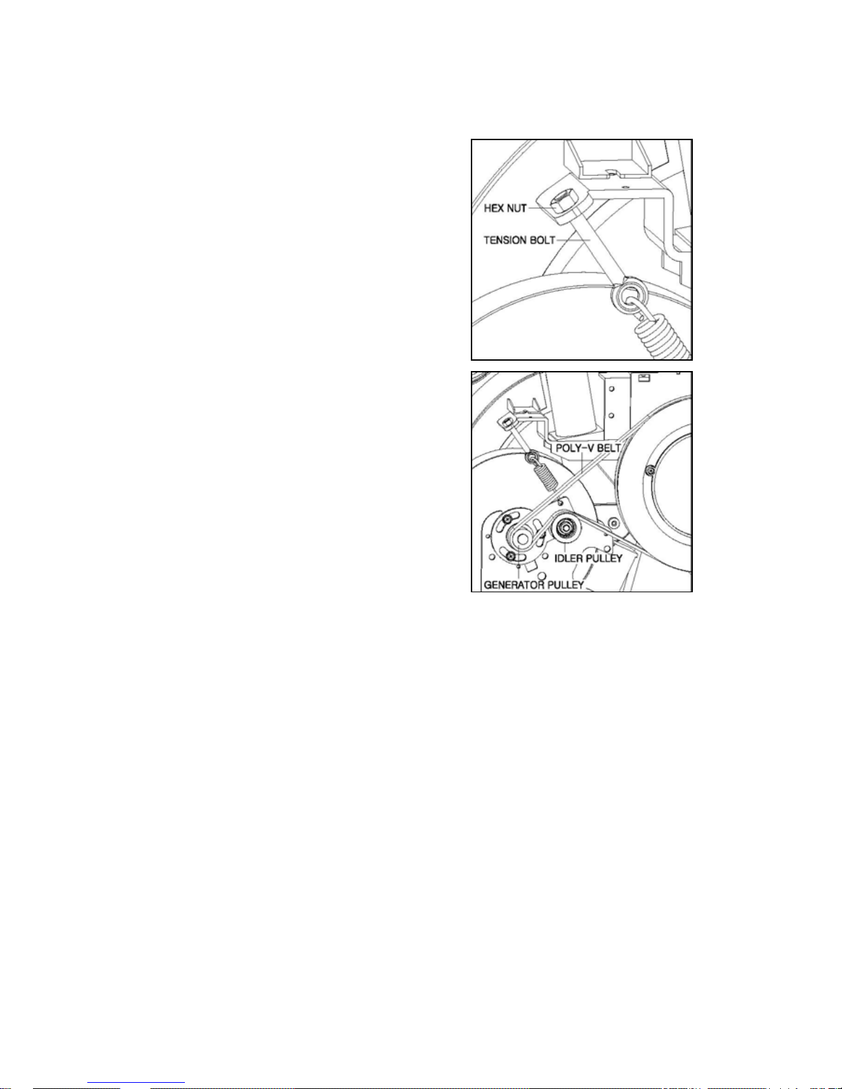
6) To decrease the belt tension, turn the HEX NUT (17) counterclockwise until the HEX NUT
(17) reaches the end side of the TENSION BOLT (16) as shown.

13
7) Remove the Drive Belt from the PEDAL PULLEY
(28) by pushing the upper surface of the Drive Belt
outward while rotating the Pedal little by little. Keep in
mind that removing the Belt under high tension may
make damages to the Belt and Bearings.
8) Install new Drive Belt in reverse order by installing
the Belt around the GENERATOR (5) PULEY first and
then walking it onto the IDLER PULLEY (8) and
PEDAL PULLEY (28).
You had better install the Belt while rotating the Pedal
little by little.
9) Adjust the tension of the Drive Belt. See 2.1 How to
Adjust the Drive Belt (or POLY V-BELT) Tension.
10) Re-install all of parts in reverse order.
Caution: To avoid risk of injury, it is recommended that
one person replaces the Belt rather than two persons.
2.2.2 M660BR/BRL
Do the steps below while referring to the following Exploded Views in Appendix.
I.1 M660BR/BRL_MAIN BODY
1) Turn off the unit power at the switch and unplug the line cord at wall outlet.
2) Remove two bolts (52) securing the CENTER FOOT_RE (59) to the Main Body Frame and
Remove the CENTER FOOT_RE (59).
3) Remove two bolts (50) securing the FRONT BODY CAP_FRONT/REAR (58, 57) to the Main
Body Frame and remove the FRONT BODY CAP_FRONT/REAR (58, 57).
4) Remove six bolts (46, 56) fastening the FRONT BODY_R (54) to the Body Frame and
remove the FRONT BODY_R (54) from the Body Frame.
5) To decrease the belt tension, turn the HEX NUT (14) counterclockwise until the HEX NUT
(14) reaches the end side of the TENSION BOLT (13) as shown.
14
6) Remove the Drive Belt from the PEDAL PULLEY
(27) by pushing the upper surface of the Drive Belt
outward while rotating the Pedal little by little. Keep in
mind that removing the Belt under high tension may
make damages to the Belt and Bearings.
7) Install new Drive Belt in reverse order by installing
the Belt around the GENERATOR (2) PULEY first and
then walking it onto the IDLER PULLEY (5) and
PEDAL PULLEY (27).
You had better install the Belt while rotating the Pedal
little by little.
8) Adjust the tension of the Drive Belt. See 2.1 How to
Adjust the Drive Belt (or POLY V-BELT) Tension.
9) Re-install all of parts in reverse order.
Caution: To avoid risk of injury, it is recommended that
one person replaces the Belt rather than two persons.
2.3. How to Replace the PEDAL SHAFT
2.3.1 M660BU/BUL
Do the steps below while referring to the following Exploded Views in Appendix.
C.1 M660BU/BUL_MAIN BODY
1) Turn off the unit power at the switch and then unplug the line cord at wall outlet.
2) Remove the CENTER FOOT_UP (61) by removing two bolts (52) securing the CENTER
FOOT_UP (61) to the Main Body Frame.
3) Remove two bolts (55) securing MAIN BODY CAP (54) to the Main Body Frame.
4) Lift the MAIN BODY CAP (54) and SEAT POST CAP (56) and then fix these to the Gas
Cylinder temporarily by a tape to make it easy to remove the MAIN BODY_R (50).
5) Remove five bolts (51, 52) securing the MAIN BODY_R (50) to the Main Body Frame and
remove the MAIN BODY_R (50).

15
6) Remove the CRANK CAP (45) from the CRANK
ARM_R (43) by using a tool with tip.
7) Remove the Bolt (44) securing the CRAMK ARM_R
(43) to the PEDAL SHAFT (27) by using 6 mm wrench.
8) The PEDAL TOOL for pulling the Crank Arm out is
shown. Maintain the PEDAL TOOL as shown in A by
placing the rear section of the PEDAL TOOL as
backward as possible.
9) Install the PEDAL TOOL into the hole of the CRANK
ARM_R (43) where the CRANK CAP (45) was extracted.
10) Insert the PEDAL TOOL into the hole of the CRANK
ARM_R (43) by turning the front hex-section of the
PEDAL TOOL clockwise with Adjustable Spanner as
shown.
11) Turn the rear hex-section of the PEDAL TOOL
clockwise as shown until the CRANK ARM_R (43) is
extracted from the PEDAL SHAFT.
12) Remove three Bolts (32) and remove the PEDAL IN
COVER (31).
13) Remove the Drive Belt (46). See 2.2 How to
Replace the Drive Belt
14) Remove the PEDAL PULLEY (28) from the unit by
removing four Bolts (29).
15) Remove the MAIN BODY_L (49), CRANK CAP (45),
CRANK ARM_L (41) and PEDAL IN COVER (31) in
opposite side while using same procedures as 5) thru
12).
16) Remove the SNAP RING (30) by using Snap Ring
Plier.
17) Pull the PEDAL SHAFT (27) out of the unit.
18) Install new PEDAL SHAFT (27) in reverse order.
19) Adjust the Drive Belt Tension before re-assembling the MAIN BODY_R (50). See “How to
Adjust the Drive Belt Tension”
20) Re-install all of parts in reverse order.

16
2.3.2 M660BR/BRL
Do the steps below while referring to the following Exploded Views in Appendix.
I.1 M660BR/BRL_MAIN BODY
1) Turn off the unit power at the switch and then unplug the line cord at wall outlet.
2) Remove the CENTER FOOT_RE (59) by removing two bolts (56) securing the CENTER
FOOT_RE (59) to the Main Body Frame.
3) Remove two bolts (50) securing the FRONT BODY CAP_FRONT/REAR (58, 57) to the Main
Body Frame and remove the FRONT BODY CAP_FRONT/REAR (58, 57).
4) Remove six bolts (46, 56) fastening the FRONT BODY_R (54) to the Body Frame and
remove the FRONT BODY_R (54) from the Body Frame.
5) Replace the Pedal Shaft while referring to 6) thru 19) in section 2.3.1 M660BU/BUL.
6) Re-install all of parts in reverse order.
2.4. How to Replace the GENERATOR
2.4.1 M660BU/BUL
Do the steps below while referring to the following Exploded Views in Appendix.
C.1 M660BU/BUL_MAIN BODY
1) Turn off the unit power at the switch and then unplug the line cord at wall outlet.
2) Remove the CENTER FOOT_UP (61) by removing two bolts (52) securing the CENTER
FOOT_UP (61) to the Main Body Frame.
3) Remove two bolts (55) securing MAIN BODY CAP (54) to the Main Body Frame.
4) Lift the MAIN BODY CAP (54) and SEAT POST CAP (56) and then fix these to the Gas
Cylinder temporarily by a tape to make it easy to remove the MAIN BODY_R (50).
5) Remove five bolts (51, 52) securing the MAIN BODY_R (50) to the Main Body Frame and
remove the MAIN BODY_R (50).
17
JACK
CABLE HOLDER
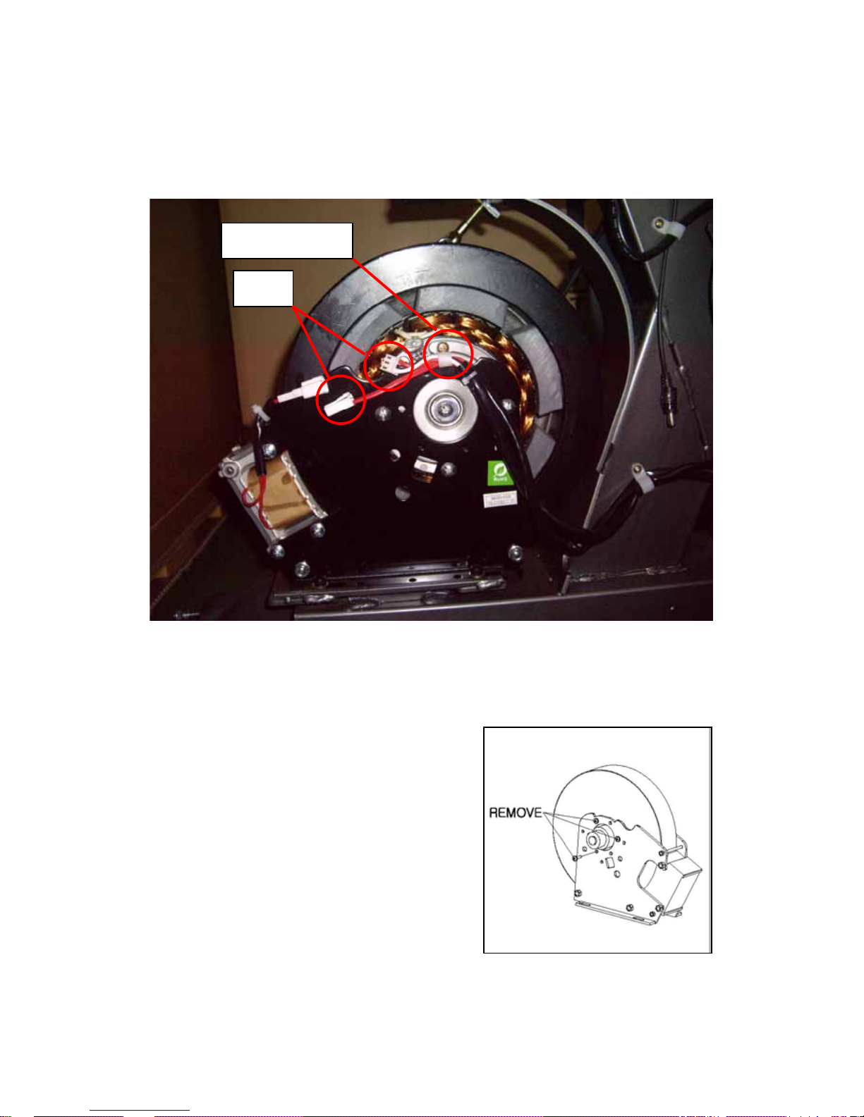
6) Remove the CABLE HOLDER and disconnect two JACKs (or connector).
7) Remove the Drive Belt while referring to section 2.2 How to Replace the Drive Belt.
8) Remove the TENSION BOLT (16) and TENSION SPRING (15) by unscrewing the HEX
BOLT (17).
9) Remove four ALLEN BOLTs (6) by using 5mm hex
wrench.
10) Lift off the GENERATOR (5) from the MAIN
FRAME (1).
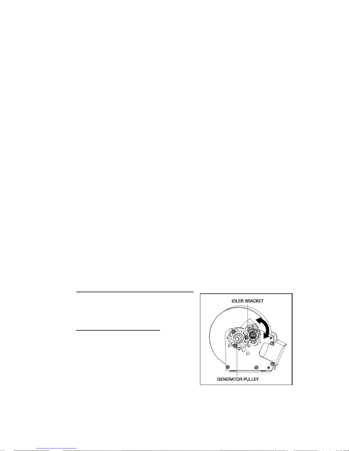
11) Remove the IDLER BRACKET (7) and IDLER
BRACKET BUSH (13) from the GENERATOR (5) by
unscrewing three bolts (14) securing the IDLER
BRACKET (7) to the GENERATOR.
12) Remove and discard three bolts on the pulley side
of new GENERATOR to be replaced as shown.
18
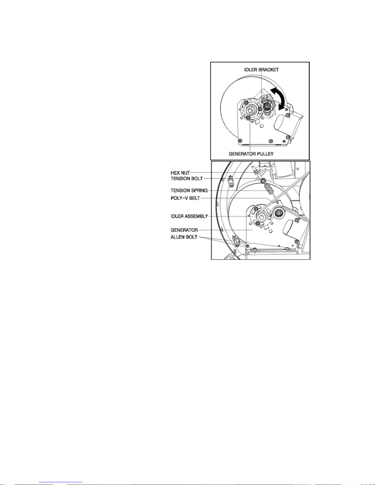
13) Install the IDLER BRACKET (7) and IDLER
BRACKET BUSH (13) onto the new GENERATOR by
screwing three bolts (14).
Note: Make sure the IDLER BRACKET (7) moves (or
rotates) a little on the pulley as shown.
14) Install new GENERATOR in reverse order.
15) re-assemble the TENSION SPRING(15),
TENSION BOLT(16) and HEX NUT(17).
16) Install the Drive Belt (46) while referring to section
2.2 How to Replace the Drive Belt.
17) Adjust the tension of the Drive Belt
while referring to section 2.1 How to
Adjust the Drive Belt (or POLY VBELT) Tension.
18) The re-assembled new
GENERATOR is shown.
19) Re-assemble all of parts in
reverse order.
2.4.2 M660BR/BRL
Do the steps below while referring to the following Exploded Views in Appendix.
I.1 M660BR/BRL_MAIN BODY
1) Turn off the unit power at the switch and then unplug the line cord at wall outlet.
2) Remove the CENTER FOOT_RE (59) by removing two bolts (56) securing the CENTER
FOOT_RE (59) to the Main Body Frame.
3) Remove two bolts (50) securing the FRONT BODY CAP_FRONT/REAR (58, 57) to the Main
Body Frame and remove the FRONT BODY CAP_FRONT/REAR (58, 57).
4) Remove six bolts (46, 56) fastening the FRONT BODY_R (54) to the Body Frame and
remove the FRONT BODY_R (54) from the Body Frame.
5) Replace the GENERATOR while referring to 6) thru 18) in section 2.4.1 M660BU/BUL.
6) Re-assemble all of parts in reverse order.
19
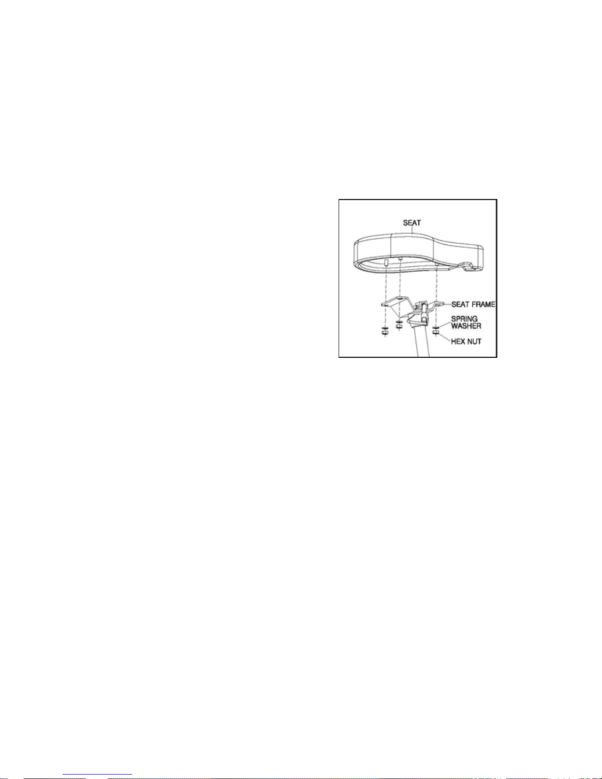
2.5. How to Replace the SEAT
2.5.1. M660BU/BUL
Do the steps below while referring to the following Exploded Views in Appendix.
F.1 M660BU/BUL_SEAT
1) Remove the SEAT (6) by unscrewing three HEX
NUTs (8) and three SPRING WASHERs (7) securing
the SEAT to the SEAT FRAME (1) by the use of 13
mm Spanner or Adjustable Spanner.
2) Discard the SEAT and install new SEAT in reverse
order.
2.5.2. M660BR/BRL
Do the steps below while referring to the following Exploded Views in Appendix.
K.1 M660BR/BRL_SEAT
2.5.2.1. SEAT
1) Remove the SEAT (21) by unscrewing four ALLEN BOLTs (22) and four SPRING WASHERs
(23) securing the SEAT to the SEAT FRAME (1)
2) Discard the SEAT (21) and install new SEAT in reverse order.
2.5.2.2. SEAT BACK
1) Remove the SEAT BACK COVER (25) by unscrewing eight TRUSS SCREWs (26) securing
the SEAT BACK COVER to SEAT BACK (24).
2) Remove four ALLEN BOLTs (22) and four SPRING WASHERs (23) securing the SEAT
BACK (24) to the SEAT FRAME (1).
3) Discard the SEAT BACK (24) and then install new SEAT BACK in reverse order.
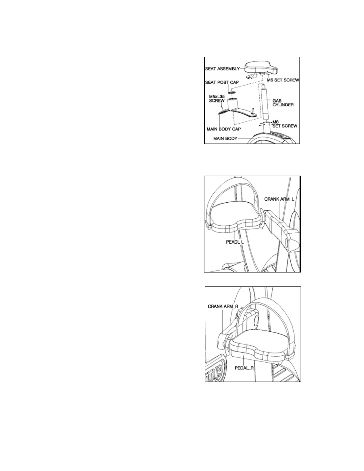
2.6. How to Replace the GAS CYLINDER
Do the steps below while referring to the following Exploded Views in Appendix.
A.1 M660BU
C.1 M660BU/BUL_MAIN BODY
20
1) Remove the SEAT ASSEMBLY (15) from the GAS
CYLINDER (38) by unscrewing four setscrews (16).
2) Remove the SEAT POST CAP (56).
3) Remove the MAIN BODY CAP (54) from the MAIN
BODY by unscrewing two screws (55).
4) Remove four setscrews (39) securing the GAS
CYLINDER (38) to the MAIN FRAME (39).
5) Install new GAS CYLINDER in reverse order.
2.7. How to Replace the PEDAL
2.7.1. Left PEDAL
The picture shown is the left Pedal as viewed from the
rear side of the bike.
1) Turn the connecting section in between the
PEDAL_L and CRANK ARM_L clockwise as shown in
picture by using Adjustable Spanner or Spanner while
holding the CRANK ARM_L.
2) Turn the PEDAL_L until it is distracted.
3) Discard the PEDAL_L and install new PEDAL_L in
reverse order.
2.7.2 Right Pedal
The picture shown is the Right Pedal as viewed from
the rear side of the bike.
1) Turn the connecting section in between the
PEDAL_R and CRANK ARM_R counterclockwise as
shown in picture by using Adjustable Spanner or
Spanner while holding the CRANK ARM_R.
2) Turn the PEDAL_R until it is distracted.
3) Discard the PEDAL_R and install new PEDAL_R in
reverse order.
21
2.8. How to Replace the IDLER ASSEMBLY
2.8.1 M660BU/BUL
Do the steps below while referring to the following Exploded Views in Appendix.
C.1 M660BU/BUL_MAIN BODY
1) For M660BUL, turn off the unit power at the switch and then unplug the line cord at wall outlet.
2) Remove the CENTER FOOT_UP (61) by removing two bolts (52) securing the CENTER
FOOT_UP (61) to the Main Body Frame.
3) Remove two bolts (55) securing MAIN BODY CAP (54) to the Main Body Frame.
4) Lift the MAIN BODY CAP (54) and SEAT POST CAP (56) and then fix these to the Gas
Cylinder temporarily by a tape to make it easy to remove the MAIN BODY_R (50).
5) Remove five bolts (51, 52) securing the MAIN BODY_R (50) to the Main Body Frame and
remove the MAIN BODY_R (50).
6) Mark the position of HEX LOCK NUT (17) on HANGER BOLT (16) for restoring BELT
tension when reassembling it.
7) Loosen HEX LOCK NUT (17) by using 13 mm spanner until it reaches the end of HANGER
BOLT (16) to slacken POLY V-BELT (46).
8) Remove POLY V-BELT (46) from PEDAL PULLEY (28), IDLER PULLEY (8) and
GENERATOR PULLEY. Be careful not to get your hands be caught between the BELT and
PULLEYS.
9) Remove IDLER BRACKET (7), IDLER BRACKET SPACER (12) and IDLER BRACKET
BUSH (13) by removing three bolts (14) securing these to the GENERATOR.
Note If you find IDLER BRACKET SPACER (12)
,
discard both IDLER BRACKET SPACER (12) and
IDLER BRACKET BUSH (13) and new IDLER
BRACKET BUSH (13) should be used for reassembling.
If no IDLER BRACKET SPACER (12),
the removed
IDLER BRACKET BUSH (13) should be used for
reassembling.
10) Install new IDLER ASEMBLY on the GENERATOR
by using three bolts (14) and IDLER BRACKET BUSH
(13). Do not tighten three bolts (14) too strongly
because it can spoil the threads of GENERATOR
plate. IDLER BRACKET SPACER (12) should not be installed.

22
11) Make sure IDLER BRACKET (7) is partially rotated smoothly on the axis of the
GENERATOR. If the rotation is not smooth, make sure it by replace IDLER BRACKET BUSH
(13) with another one.
12) Install POLY V-BELT (46) in reverse order and then adjust the position of POLY V-BELT
(46) to be located in the center of IDLER PULLEY (8) by rotating the pedal. The POLY V-BELT
(46) can be aligned by using the Groove of PEDAL PULLEY (28).
13) Adjust the tension of the POLY V-BELT (46) by moving HEX LOCK NUT (17) into the
position marked in 4).
14) Make sure POLY V-BELT (46) is located in the center of IDLER PULLEY (8) when you are
pedaling. If the POLY V-BELT (46) drifts off the center of IDLER PULLEY (8), realign the BELT
by using the Groove of PEDAL PULLEY (28).
15) Install all of other parts in reverse order.

23
Motus Exercise Bikes M660BU, M660BUL, M660BR and M660BRL
SECTION III
HOW TO REPLACE & REPAIR GUIDE
Electronic PCB
3.1 How to Replace the LCD Screen in Model M660BUL or M660BRL
3.2 How to Replace the A/D Board in Model M660BUL or M660BRL
3.3 How to Replace the MPU Board in Model M660BUL or M660BRL
3.4 How to Replace the MPU Board in Model M660BU or M660BR
3.5 How to Replace the OPERATION BUTTON Board
3.6 How to Replace the LAMP INVERTER Board in Model M660BUL or
M660BRL
3.7 How to Replace the Program BUTTON Board, OSD BUTTON Board &
AUDIO INTERFACE & DOWNLOAD Board in Model M660BUL and M660BRL
3.8 How to Replace the DRIVE Board.
3.9 How to Replace the SMPS-5V (or MPU POWER SUPPLY)
3.10 How to Replace the LCD POWER ADAPTER.

24
3.1 How to Replace the LCD Screen in Model M660BUL or M660BRL
Do the steps below while referring to the following Exploded Views in Appendix and Section 4
ELECTRONIC PCB, CONNECTOR AND CABLE OVERVIEW.
D.1 M660BU/BUL_CONSOLE POST
G.1 CONSOLE, M660BUL/BRL_CONSOLE
J.1 M660BR/BRL_CONSOLE POST
Note: The steps below are performed based on Upright Bike while referring to D. 1
M660BU/BUL_CONSOLE POST and .G.1 CONSOLE, M660BUL/BRL_CONSOLE.
1) Turn off the unit power at the switch and then unplug the line cord at wall outlet.
2) Remove the DISPLAY REAR COVER (13, D.1) from the DISPLAY PANEL BOTTM (10, D.1)
by unscrewing four screws (8, D.1).
3) Remove the DISPLAY PANEL TOP (12, D.1) from the DISPLAY PANEL BOTTOM (10, D.1)
by unscrewing four screws (11, D.1) securing the DISPLAY PANEL TOP (12, D.1).
4) Disconnect all the cables from the DISPLAY PANEL TOP (12, D.1) and then place the
DISPLAY PANEL TOP (12, D.1) on the flat and clean surface so that the LCD screen faces
downward.
5) Disconnect one end of the OSD BUTTON CABLE (CB21) from the side of A/D BOARD (8,
G.1). The OSD BUTTON CABLE (CB21) is connected in between the A/D BOARD (8, G.1) and
OSD BOARD (11, G.1).
6) Remove the LCD PANEL BRACKET (3, G.1) from the DISPLAY PANEL TOP (1, G.1) by
unscrewing six screws (7, G.1).
7) Disconnect one end of the LVDS CABLE (CB31) from the side of the LCD PANEL (2, G.1).
The other end of the LVDS CABLE (CB31) doesn’t need to be disconnected from the A/D
BOARD (8, G.1).
8) Disconnect the LAMP INVERTER CABLE (CB32) from the LAMP INVERTER (6, G1).
9) Place the LCD BRACKET (3, G.1) upside down so that the LCD PANEL (2, G.1) faces
upward.
10) Remove the LCD PANEL (2, G.1) by unscrewing four screws (4, G.1) securing the LCD
PANEL (2, G.1) to the LCD BRACKET.
11) Install new LCD PANEL (2, G.1) in reverse order.

25
3.2 How to Replace the A/D Board in Model M660BUL or M660BRL
Do the steps below while referring to the following Exploded Views in Appendix and Section 4
ELECTRONIC PCB, CONNECTOR AND CABLE OVERVIEW.
D.1 M660BU/BUL_CONSOLE POST
G.1 CONSOLE, M660BUL/BRL_CONSOLE
1) Turn off the unit power at the switch and then unplug the line cord at wall outlet.
2) Remove the DISPLAY REAR COVER (13, D.1) from the DISPLAY PANEL BOTTM (10, D.1)
by unscrewing four screws (8, D.1).
3) Remove four screws (11, D.1) securing the DISPLAY PANEL TOP (12, D.1) to the DISPLAY
PANEL BOTTOM (10, D.1).
4) Lift off the DISPLAY PANEL TOP (12, D.1) while disconnecting all the cables from the
DISPLAY PANEL TOP (12, D.1) and then place the DISPLAY PANEL TOP (12, D.1) on the flat
and clean surface so that the LCD screen faces downward.
5) Disconnect all the cables from the A/D BOARD (8, G.1).
6) Remove the A/D BOARD (8, G.1) from the LCD PANEL BRACKET (3, G.1) by unscrewing
four screws (7, G.1).
7) Install new A/D BOARD (8, G.1) in reverse order.

26
3.3 How to Replace the MPU Board in Model M660BUL or M660BRL
Do the steps below while referring to the following Exploded Views in Appendix and Section 4
ELECTRONIC PCB, CONNECTOR AND CABLE OVERVIEW.
D.1 M660BU/BUL_CONSOLE POST
G.1 CONSOLE, M660BUL/BRL_CONSOLE
1) Turn off the unit power at the switch and then unplug the line cord at wall outlet.
2) Remove the DISPLAY REAR COVER (13, D.1) from the DISPLAY PANEL BOTTM (10, D.1)
by unscrewing four screws(8, D.1).
3) Remove four screws (11, D.1) securing the DISPLAY PANEL TOP (12, D.1) to the DISPLAY
PANEL BOTTOM (10, D.1).
4) Lift off the DISPLAY PANEL TOP (12, D.1) while disconnecting all the cables from the
DISPLAY PANEL TOP (12, D.1) and then place the DISPLAY PANEL TOP (12, D.1) on the flat
and clean surface so that the LCD screen faces downward.
5) Disconnect all the cables from the MPU BOARD_FRONT (13, G1).
6) Remove three screws (7, G.1) securing the MPU BOARD_BACK (15, G.1) to the MPU
BOARD_FRONT (13, G.1).
7) Carefully lift the MPU BOARD_BACK (15, G.1) off the MPU BOARD_FRONT (13, G.1) so
that the pins on the both edges of the MPU BOARD_FRONT are not damaged or bended.
8) Remove four screws (12, G.1) and three HEXGON SPACER (14, G.1) securing the MPU
BOARD_FRONT (13, G.1) to the DISPLAY PANEL_TOP (1, G.1).
9) Lift off the MPU BOARD_FRONT (13, G.1)
10) Install new MPU BOARD_FRONT or MPU BOARD_BACK in reverse order.

27
3.4 How to Replace the MPU Board in Model M660BU or M660BR
Do the steps below while referring to the following Exploded Views in Appendix and Section 4
ELECTRONIC PCB, CONNECTOR AND CABLE OVERVIEW.
D.1 M660BU/BUL_CONSOLE POST
G.1 CONSOLE, M660BU/BR_CONSOLE
1) Remove the DISPLAY REAR COVER (13, D.1) from the DISPLAY PANEL BOTTM (10, D.1)
by unscrewing four screws (8, D.1).
2) Remove four screws (11, D.1) securing the DISPLAY PANEL TOP (12, D.1) to the DISPLAY
PANEL BOTTOM (10, D.1).
3) Lift off the DISPLAY PANEL TOP (12, D.1) while disconnecting all the cables from the
DISPLAY PANEL TOP (12, D.1) and then place the DISPLAY PANEL TOP (12, D.1) on the flat
and clean surface so that it faces downward.
4) Disconnect all the cables including Ribbon cable from the MPU BOARD (27, G1).
5) Remove eight screws (12, G.1) securing the MPU BOARD (27, G1) to the DI SPLAY PANEL
TOP (1, G.1).
6) Lift off the MPU BOARD (27, G1) out of the DISPLAY PANEL TOP (1, G.1).
7) Install new MPU BOARD (27, G1) in reverse order.

28
3.5 How to Replace the OPERATION BUTTON Board
Do the steps below while referring to the following Exploded Views in Appendix and Section
4
ELECTRONIC PCB, CONNECTOR AND CABLE OVERVIEW.
D.1 M660BU/BUL_CONSOLE POST
G.1 CONSOLE
1) If the machine is M660BUL or M660BRL with LCD monitor, turn off the unit power at the
switch and then unplug the line cord at wall outlet.
2) Remove the DISPLAY REAR COVER (13, D.1) from the DISPLAY PANEL BOTTM (10, D.1)
by unscrewing four screws (8, D.1).
2) Remove four screws (11, D.1) securing the DISPLAY PANEL TOP (12, D.1) to the DISPLAY
PANEL BOTTOM (10, D.1).
3) Lift off the DISPLAY PANEL TOP (12, D.1) while disconnecting all the cables from the
DISPLAY PANEL TOP (12, D.1) and then place the DISPLAY PANEL TOP (12, D.1) on the flat
and clean surface so that it faces downward.
4) Disconnect all of cables from the OPERATION BUTTON BOARD (21, G.1).
5) Remove the OPERATION BUTTON BOARD from the DISPLAY BUTTON CONTROL (20,
G.1) by unscrewing five screws (12, G.1).
6) Install new OPERATION BUTTON BOARD (21, G.1) in reverse order.
 Loading...