

Motura Xmode F1.0, Xmode M 2.0 Maintance Manual
POWERED ELECTRONIC LOCK
OPERATION AND MAINTENANCE INSTRUCTIONS
USER MANUAL
M 2.0/F1.0
RECHARGEABLE
SYSTEM CODE
GLUE THE LOCK SYSTEM CODE
LABEL HERE
TABLE OF CONTENTS
1 - GENERAL INSTRUCTIONS ............................................................................. pag. 3
1.1 - WARRANTY TERMS
1.2 - LIMITS OF LIABILITY
2 - ESCUTCHEONS ............................................................................................................ 4
2.1 - INTERNAL ESCUTCHEON WITH KEYPAD
2.2 - INTERNAL ESCUTCHEON WITH DISPLAY
2.3 - EXTERNAL ESCUTCHEON WITH KEYPAD-TRANSPONDER
2.4 - EXTERNAL ESCUTCHEON WITH TRANSPONDER
3 - TRANSPONDER KEYS (TAGS) ......................................................................... 6
3.1 - TRANSPONDER KEY
3.2 - TRANSPONDER KEY WITH INTEGRATED CHAMPIONS® KEY
3.3 - TRANSPONDER CARD
3.4 - GREEN TRANSPONDER CARD (ONLY FOR PROTECTED TAG SYSTEM)
3.5 - TAG KEYS: BASIC CONCEPTS
4 - PROCEDURE FOR ENTERING PROGRAMMING MODE ..................................... 8
5 - MANAGING TAG KEYS ............................................................................................... 8
5.1 - MEMORIZING MASTER TAG KEYS
5.2 - MEMORIZING SERVICE TAG KEYS
5.3 - DISABLING SERVICE TAG KEYS
5.4 - RESETTING SERVICE TAG KEYS
5.5 - DELETING INDIVIDUAL TAG KEYS
5.6 - DELETING ALL TAG KEYS
6 - LOCK OPERATION MODES ....................................................................................... 10
6.1 - PROGRAMMING LOCK OPERATION MODES
6.2 - ACTIVATING / DEACTIVATING THE SECURITY CODE FROM THE INSIDE
7 - LOCK OPERATION WITH TAG KEYS ......................................................................... 11
8 - LOCK OPERATION WITH KEYPAD AND TAG KEYS .............................................. 12
8.1 - MEMORIZING PERSONAL ACCESS CODES
8.2 - DELETING A PERSONAL ACCESS CODE
8.3 - DELETING ALL PERSONAL ACCESS CODES
9 - POWERING THE LOCK ................................................................................................. 13
9.1 - CHECKING POWER SUPPLY STATUS
10 - MAINS POWER SUPPLY .............................................................................................. 14
11 - BATTERY POWER SUPPLY .......................................................................................... 14
11.1 - DOUBLE TUBE VERSION
11.2 - CASSETTE VERSION
12 - PERIPHERAL .................................................................................................................. 15
13 - NOTES ON USING THE SERVICE CYLINDER ....................................................... 15
14 - NOTES ON USING THE MASTER CYLINDER ....................................................... 15
15 - DESCRIPTIONS OF LED SIGNALS .......................................................................... 15
16 - DESCRIPTION OF ACOUSTIC SIGNALS ............................................................... 15
17 - TROUBLESHOOTING ................................................................................................. 16
18 - SIGNAL SUMMARY TABLE ....................................................................................... 17
2
99286GB- XMODE – USER MANUAL - REV. 01
1 - GENERAL INSTRUCTIONS
Mottura Serrature di Sicurezza S.p.A. thanks you for choosing this product and reminds you:
- To read all of these instructions very carefully before installing the lock or doing any maintenance work on the product.
- That all assembly and connection procedures must be done in conformity to the rules of Good Practice and to current law. DO NOT install this
product in rooms or atmospheres at risk of explosion or in the presence of ammable fumes/gases.
- Do not install the lock on doors with risk of contact with water or atmospheric agents if not properly protected.
- To switch o the power supply and disconnect all live parts before doing any installation or maintenance work on the product. Take all possible precautions to eliminate the risk of electrical shock when doing the installation or maintenance procedures described in this manual.
- The installer must deliver these instructions and all of the maintenance instructions to the user.
- Keep these instructions for future reference and attach the sales receipt to validate the warranty.
- In case of problems contact authorized dealers only.
Mottura Serrature di Sicurezza S.p.A. may change the characteristics of the products described in these instructions at any time and without notice.
1.1 - WARRANTY TERMS
This product has been inspected by Mottura Serrature di Sicurezza S.p.A. and is guaranteed to be free of all manufacturing defects for the time
specied by current Italian law, starting on the date of purchase indicated on the sales receipt.
The warranty is in force if the sales receipt, showing details identifying the product, is exhibited to customer service personnel.
The warranty covers the replacement or repair of parts found defective at origin due to manufacturing defects. Costs of shipping to and from
service centers will be paid by the customer.
In case of repeated malfunctions of the same type or unrepairable defects, Mottura Serrature di Sicurezza S.p.A. may, at its own discretion, replace
the complete product. The warranty on the replaced product will continue until expiration of the original warranty.
If work is necessary at the customer’s home, the customer will be required to pay a charge for the costs of transfer of authorized technical personnel.
Transport will be at the customer’s risk if the product is sent by the customer and at the authorized technician’s risk if the product is picked up and
transported by the technician.
1.2 - LIMITS OF LIABILITY
The warranty does not cover damage due to:
- negligence, carelessness or use in any manner not described in these instructions
- lack of protection of the lock prior to carrying out any work operations on the door, such as drilling or welding (welds, panel holes, structure
holes, etc.), which may generate waste materials that will hinder the correct operation of the lock upon entering its mechanism
- maintenance performed in any manner not described in these instructions or by unauthorized personnel
- use of non-original accessories/components Mottura
- transport without the necessary precautions
and from any circumstances that cannot be attributed to manufacturing defects.
Work temperature: -10°C to +55°C. The batteries guarantee correct operation of the lock in the specied temperature range. If such temperature
extremes are approached or exceeded, battery performance may decrease rapidly, with possible malfunction of the electrical part. In case of extremely low temperatures, it is advisable to power the lock from the mains by using the 230/12 V transformer.
In addition, Mottura Serrature di Sicurezza S.p.A. declines all liability for any damage to persons or property deriving from failure to observe all of
the precautions described herein.
N.B. Mechanical lock operation is guaranteed even when the electronics of the lock has no anomaly. This excludes any electronic
safety level. Mechanical keys should therefore only be used by the owner and/or by extremely trustworthy persons.
3
2 - ESCUTCHEONS
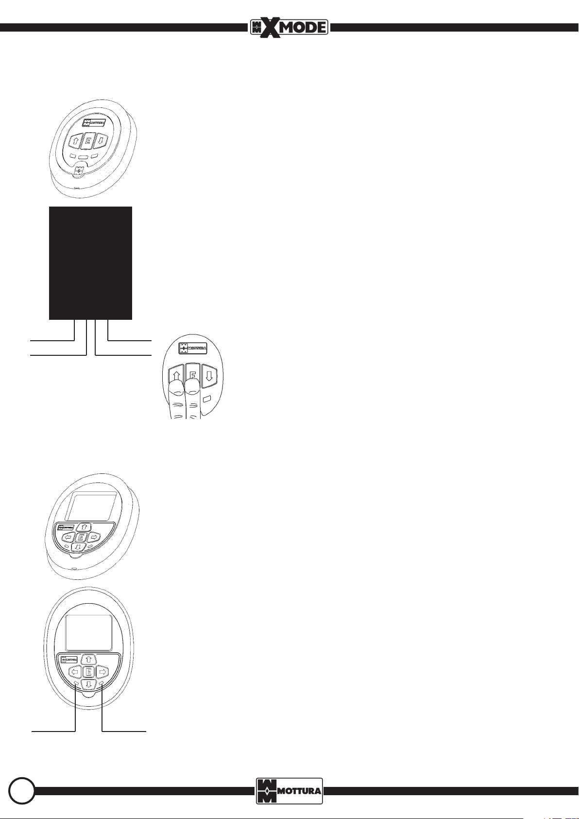
2.1 - INTERNAL ESCUTCHEON with KEYPAD
The internal escutcheon has a keypad with 3 function keys and 4 LEDs (red-yellow-blue-green).
The function keys are:
- up/down arrow: to select and conrm programming
- E (Enter): to open/close lock in normal use.
The LEDs show lock status or execution of an operation by means of light signals identical to those of the external escutcheon:
- RED LED ashing lock closed
- RED LED steady on lock closing
- GREEN LED ashing lock open
- GREEN LED steady on lock opening
- GREEN and RED LEDs steady on lock in programming phase
- YELLOW and BLUE LEDs programming signals
- All LEDs steady on for 2 seconds when “E” key is pressed internal security code active
Beeps signal to conrm when the lock has been opened or closed.
If the system is not used, it goes into stand-by after 5 seconds to save energy:
- lock active .......................... ash every second
- lock in stand-by .....…..…ash every 4 seconds
You can also use the keypad to check the type of power supply and, in case of battery
power, check the charge level (see paragraph 8.1).
RED LED GREEN LED
YELLOW LED BLUE LED
2.2 - INTERNAL ESCUTCHEON with DISPLAY
The escutcheon includes the following components:
- a color display OLED, a matrix of 160 x 128 pixels, the size of 1.69 "
- a keyboard with ve keys, four of which (arrow keys) are used to move menu entry and one (the "E" key) is used
to conrm the choices you made earlier.
E (Enter): to open/close lock in normal use
- the LEDs show lock status or execution of an operation by means of light signals identical to those of the
external escutcheon:
- RED LED ashing lock closed
- RED LED steady on lock closing
- GREEN LED ashing lock open
- GREEN LED steady on lock opening
Beeps signal to conrm when the lock has been opened or closed.
If the system is not used, it goes into stand-by after 5 seconds to save energy:
- lock active .......................... ash every second
- lock in stand-by .....…..…ash every 4 seconds
To use the display escutcheon refer to the appropriate instruction manual supplied with the product.
Only with the door closed, press the up arrow + E keys simultaneously for 3 seconds.
The LEDs will signal as follows:
- BLUE LED steady on ...............................................………….............………………… grid power
- GREEN LED steady on ...........................................…….…………….power (batteries ecient)
- BLUE LED steady on + GREEN steady on ............................……............... grid + battery power
- YELLOW LED steady on + 3 beeps ................................................... reminder to replace batteries
- YELLOW LED steady on + double high-low sound............................................ batteries drained
The reminder to replace the batteries is given before any operation is done (opening/
closing, etc.). You should replace the batteries as soon as possible to ensure correct functioning of the lock.
RED LED GREEN LED
4
99286GB- XMODE – USER MANUAL - REV. 01
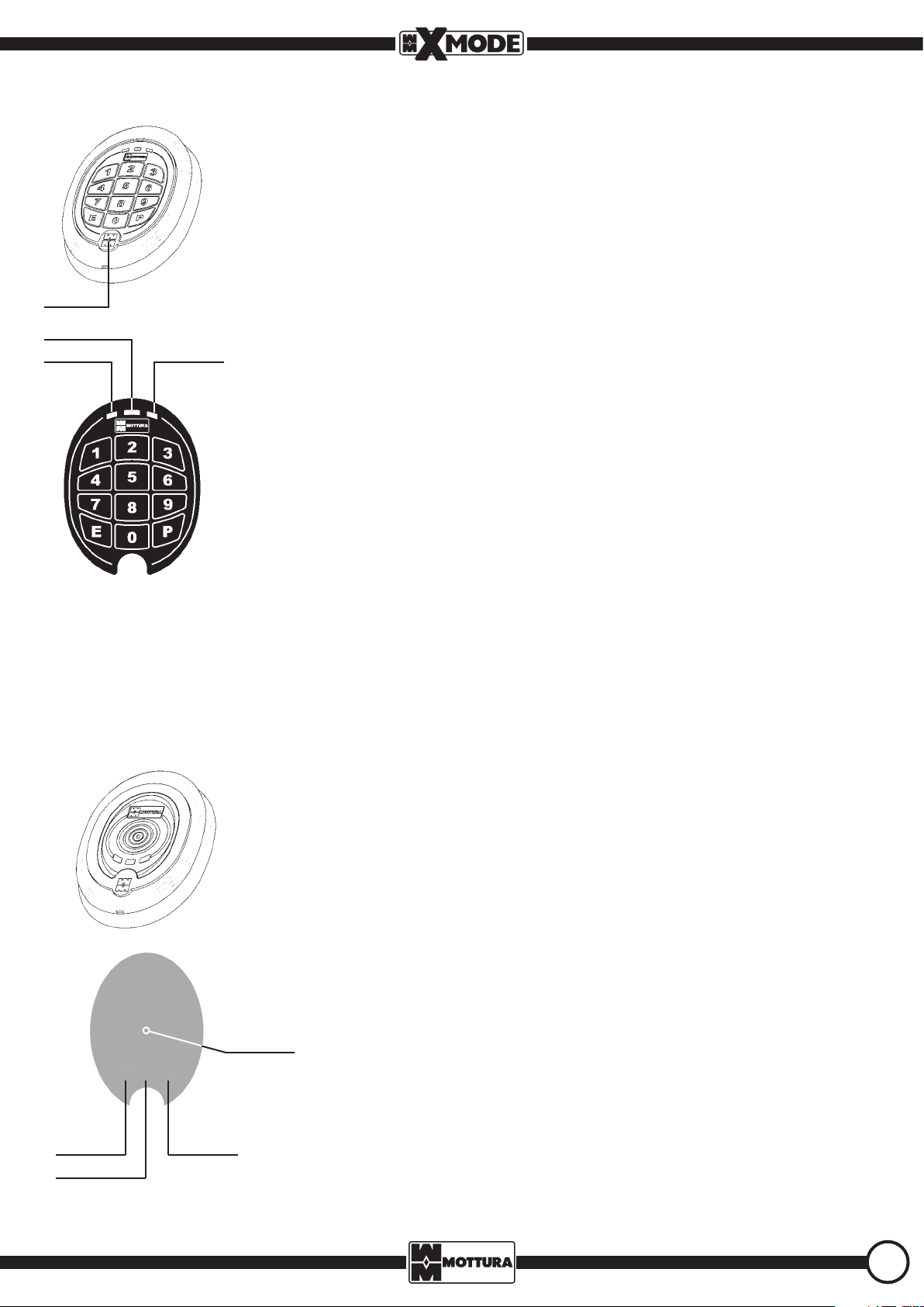
2.3 - EXTERNAL ESCUTCHEON with KEYPAD-TRANSPONDER
The backlighted external escutcheon with KEYPAD/TRANSPONDER has 12 function keys, a transponder reader (RFID), a buzzer, and three LEDs (RED-YELLOW-GREEN).
It provides 2 ways to open/close the lock:
- numerical PIN: the keypad lets you enter a PIN (3 to 8 digits) with which to operate the lock.
- transponder key (TAG): the escutcheon checks the presence of a transponder key (TAG) positioned
close to the MM logo at the bottom (zone B).
The function keys are:
- number keys: to enter codes
zone B
YELLOW LED
RED LED
GREEN LED
- P (Programming): to enter the programming phase.
- E (Enter): to open/close the door (after entering the code) in normal use; conrms a selection in
programming phase.
The LEDs show door status or execution of an operation by means of light signals:
- RED LED ashing lock closed
- RED LED steady on lock closing
- GREEN LED ashing lock open
- GREEN LED steady on lock opening
- YELLOW LED programming signals
Beeps signal to conrm when the lock has been opened or closed.
- YELLOW LED steady on + 3 beeps reminder to replace batteries
- YELLOW LED steady on + double high-low sound batteries drained
The reminder to replace the batteries is given before any operation is done (opening/closing, etc.).
You should replace the batteries as soon as possible to ensure correct functioning of the lock.
2.4 - EXTERNAL ESCUTCHEON with TRANSPONDER
The external escutcheon with TRANSPONDER has a transponder reader (RFID), a buzzer, and three LEDs
(RED-YELLOW-GREEN). It checks the presence of a transponder key (TAG) placed as close as possible to the
read zone located in the center (zone A).
The LEDs, just like the internal escutcheon, show the status of the lock or the execution of an operation by
means of light signals:
- RED LED ashing lock closed
- RED LED steady on lock closing
- GREEN LED ashing lock open
- GREEN LED steady on lock opening
- YELLOW LED programming signals
Beeps signal to conrm when the lock has been opened or closed.
zone A
RED LED
YELLOW LED
GREEN LED
5
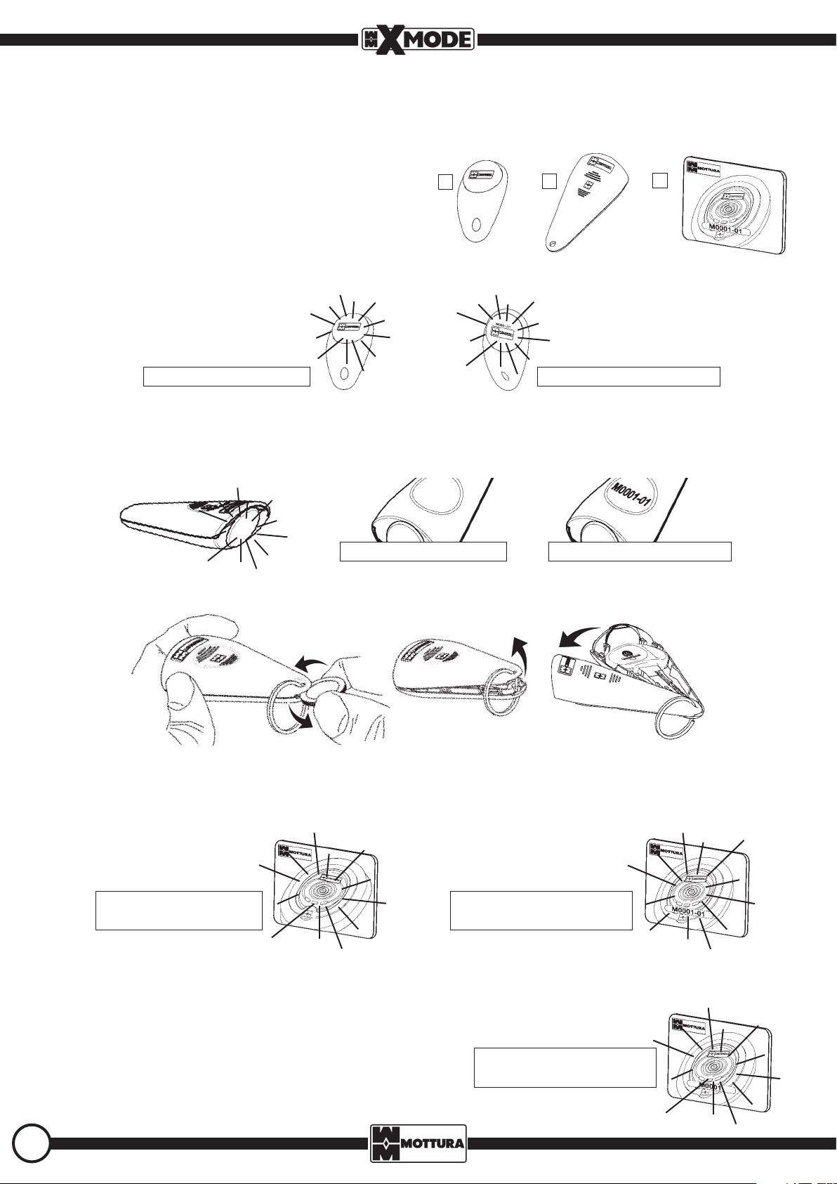
3 - TRANSPONDER KEYS (TAGs)
The term TAG refers to all types of transponder keys, which may be FREE DUPLICATION (200 max – Free TAG system) or PROTECTED DUPLICATION
(255 max with dierent code - Protected TAG system).
There are three versions:
- TRANSPONDER KEY [1]
- TRANSPONDER KEY with INTEGRATED CHAMPIONS® KEY [2]
- TRANSPONDER CARD [3]
1
2
3.1 - TRANSPONDER KEY (TAG)
The basic TAG has the transponder in an ergonomic shell placed in the top of the key where the Mottura logo is inserted and, in the Protected TAG
system, the number (ex.: M0001/F0001..) of the system to which it belongs, followed by the key code.
3
Free TAG system
Protected TAG system
3.2 - TRANSPONDER KEY (TAG) WITH INTEGRATED CHAMPIONS® KEY
In the integrated version, the transponder key contains the transponder in the top and can integrate the CHAMPIONS® key so that in case of
emergency the key is immediately available and can open the lock mechanically. In a Protected TAG system the number (ex.: M0001/F0001..) of
the system to which it belongs, followed by the key code, is inserted in the bottom of the transponder key.
Free TAG system
To integrate the key, simply insert it in the plastic shell of the transponder key. By gently applying pressure with a coin or a at screwdriver on the
notch of the transponder key near the hole for the key ring, the shell will open and the CHAMPIONS® key can be inserted or extracted, as shown
in the gure below.
To prevent the shell from being damaged as a result of continuous opening and closing, the key inside the shell should be used ONLY in emergencies (power failure, drained batteries, etc.).
Protected TAG system
3.3 - TRANSPONDER CARD (TAG)
The TAG has the transponder inserted in a card in the center. In a free TAG system the card is ORANGE.
In a Protected TAG system the card is YELLOW and shows the number (ex.: M0001/F0001..) of the system to which it belongs, followed by the key
code.
FREE TAG system
ORANGE CARD
PROTECTED TAG system
YELLOW CARD
3.4 - GREEN TRANSPONDER (TAG) CARD (ONLY FOR PROTECTED TAG SYSTEM)
This TAG is EXCLUSIVE for each lock. It is not used to open/close the lock, but instead to program the lock or to demonstrate legitimate ownership
in order to request duplicates of TAG keys (done only by Mottura serrature di sicurezza SpA’s authorized dealers).
If it is lost, no duplicate is issued. This protects the legitimate owner and prevents
anyone who may have the card (even temporarily) from requesting an unauthorized duplicate. Therefore, it must be stored carefully in a safe place. The characters printed in the white eld specify the lock system code (in the example:
M0001/F0001..).
PROTECTED TAG system
GREEN CARD
6
99286GB- XMODE – USER MANUAL - REV. 01
 Loading...